AC temperature sensor MITSUBISHI 380 2005 User Guide
[x] Cancel search | Manufacturer: MITSUBISHI, Model Year: 2005, Model line: 380, Model: MITSUBISHI 380 2005Pages: 1500, PDF Size: 47.87 MB
Page 715 of 1500
AUTO A/C DIAGNOSIS
HEATER, AIR CONDITIONING AND VENTILATION55-14
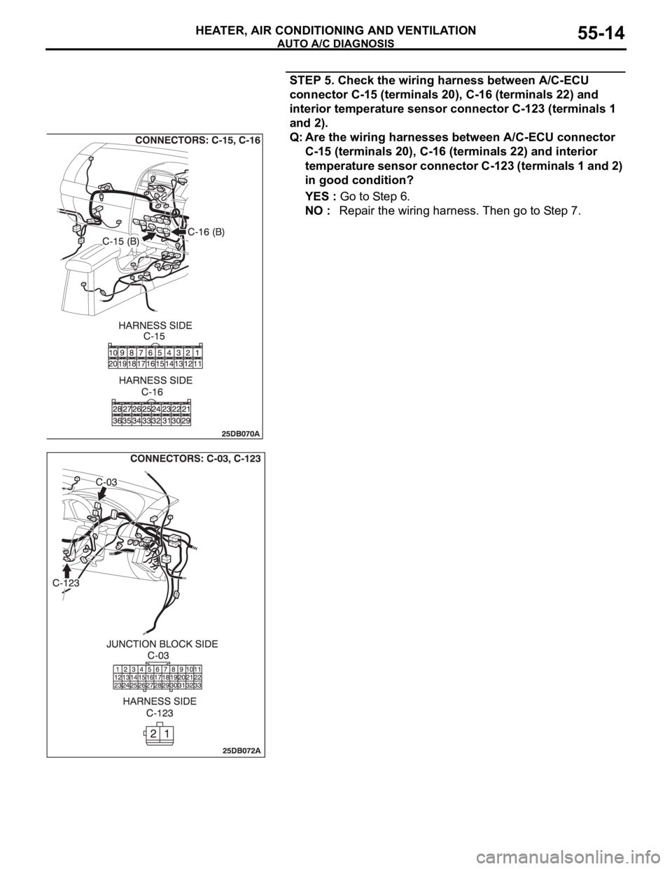
STEP 5. Check the wiring harness between A/C-ECU
connector C-15 (terminals 20), C-16 (terminals 22) and
interior temperature sensor connector C-123 (terminals 1
and 2).
Q: Are the wiring harnesses between A/C-ECU connector
C-15 (terminals 20), C-16 (terminals 22) and interior
temperature sensor connector C-123 (terminals 1 and 2)
in good condition?
YES : Go to Step 6.
NO : Repair the wiring harness. Then go to Step 7.
Page 716 of 1500
AUTO A/C DIAGNOSIS
HEATER, AIR CONDITIONING AND VENTILATION55-15
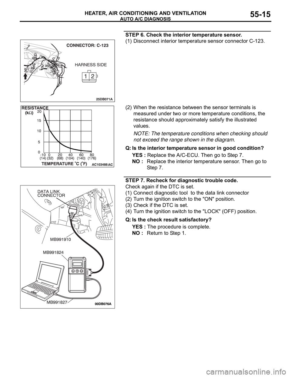
STEP 6. Check the interior temperature sensor.
(1) Disconnect interior temperature sensor connector C-123.
(2) When the resistance between the sensor terminals is
measured under two or more temperature conditions, the
resistance should approximately satisfy the illustrated
values.
NOTE: The temperature conditions when checking should
not exceed the range shown in the diagram.
Q: Is the interior temperature sensor in good condition?
YES : Replace the A/C-ECU. Then go to Step 7.
NO : Replace the interior temperature sensor. Then go to
St e p 7 .
STEP 7. Recheck for diagnostic trouble code.
Check again if the DTC is set.
(1) Connect diagnostic tool to the data link connector
(2) Turn the ignition switch to the "ON" position.
(3) Check if the DTC is set.
(4) Turn the ignition switch to the "LOCK" (OFF) position.
Q: Is the check result satisfactory?
YES : The procedure is complete.
NO : Return to Step 1.
Page 717 of 1500
AUTO A/C DIAGNOSIS
HEATER, AIR CONDITIONING AND VENTILATION55-16
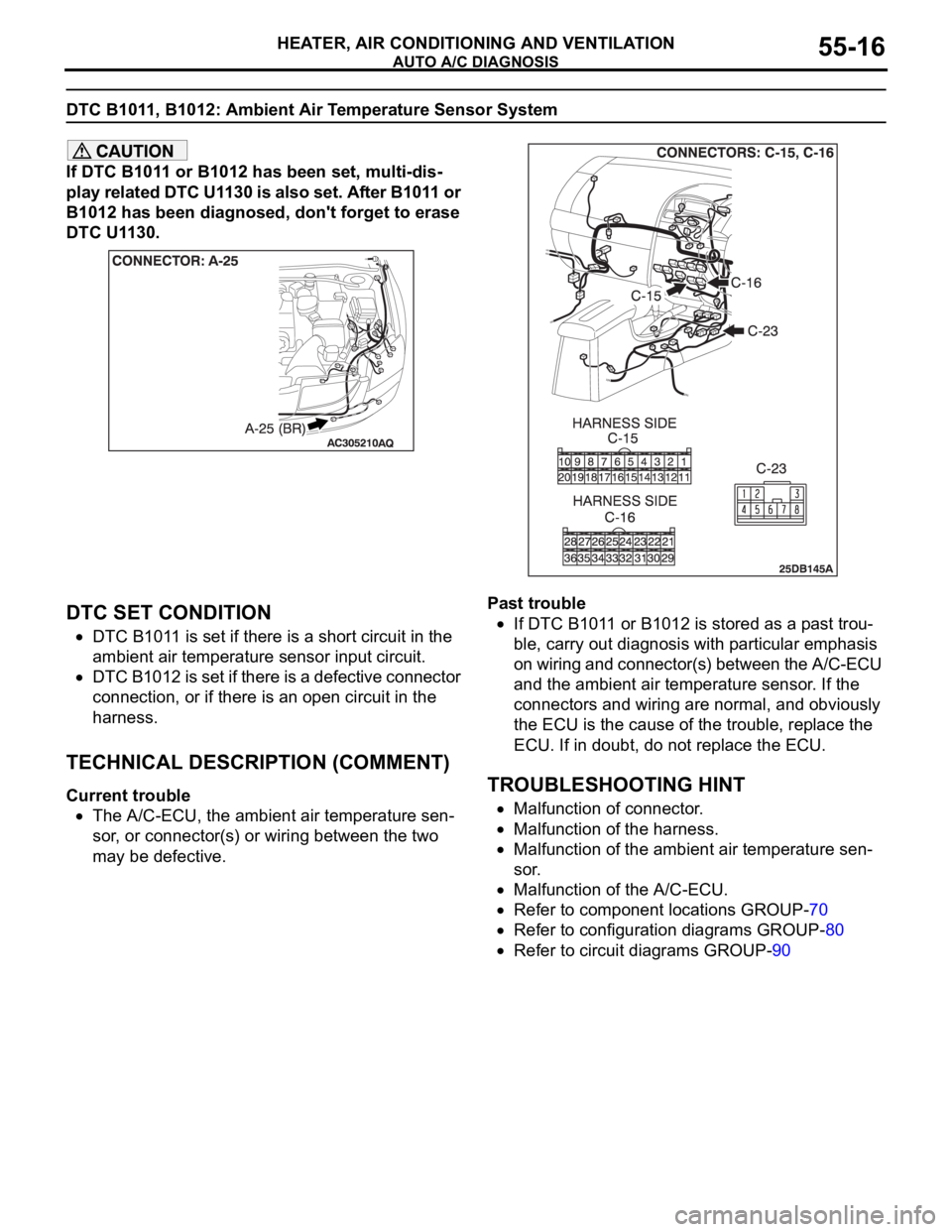
DTC B1011, B1012: Ambient Air Temperature Sensor System
If DTC B1011 or B1012 has been set, multi-dis-
play related DTC U1130 is also set. After B1011 or
B1012 has been diagnosed, don't forget to erase
DTC U1130.
.
DTC SET CONDITION
DTC B1011 is set if there is a short circuit in the
ambient air temperature sensor input circuit.
DTC B1012 is set if there is a defective connector
connection, or if there is an open circuit in the
harness.
.
TECHNICAL DESCRIPTION (COMMENT)
Current trouble
The A/C-ECU, the ambient air temperature sen-
sor, or connector(s) or wiring between the two
may be defective.Past trouble
If DTC B1011 or B1012 is stored as a past trou-
ble, carry out diagnosis with particular emphasis
on wiring and connector(s) between the A/C-ECU
and the ambient air temperature sensor. If the
connectors and wiring are normal, and obviously
the ECU is the cause of the trouble, replace the
ECU. If in doubt, do not replace the ECU.
TROUBLESHOOTING HINT
Malfunction of connector.
Malfunction of the harness.
Malfunction of the ambient air temperature sen-
sor.
Malfunction of the A/C-ECU.
Refer to component locations GROUP-70
Refer to configuration diagrams GROUP-80
Refer to circuit diagrams GROUP-90
Page 719 of 1500
AUTO A/C DIAGNOSIS
HEATER, AIR CONDITIONING AND VENTILATION55-18
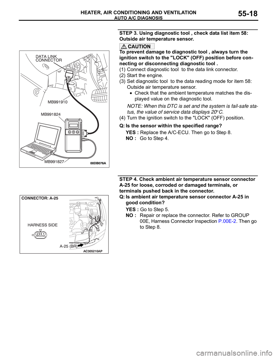
STEP 3. Using diagnostic tool , check data list item 58:
Outside air temperature sensor.
To prevent damage to diagnostic tool , always turn the
ignition switch to the "LOCK" (OFF) position before con-
necting or disconnecting diagnostic tool .
(1) Connect diagnostic tool to the data link connector.
(2) Start the engine.
(3) Set diagnostic tool to the data reading mode for item 58:
Outside air temperature sensor.
Check that the ambient temperature matches the dis-
played value on the diagnostic tool.
NOTE: When this DTC is set and the system is fail-safe sta-
tus, the value of service data displays 20
C.
(4) Turn the ignition switch to the "LOCK" (OFF) position.
Q: Is the sensor within the specified range?
YES : Replace the A/C-ECU. Then go to Step 8.
NO : Go to Step 4.
STEP 4. Check ambient air temperature sensor connector
A-25 for loose, corroded or damaged terminals, or
terminals pushed back in the connector.
Q: Is ambient air temperature sensor connector A-25 in
good condition?
YES : Go to Step 5.
NO : Repair or replace the connector. Refer to GROUP
00E, Harness Connector Inspection P.00E-2. Then go
to Step 8.
Page 720 of 1500
AUTO A/C DIAGNOSIS
HEATER, AIR CONDITIONING AND VENTILATION55-19
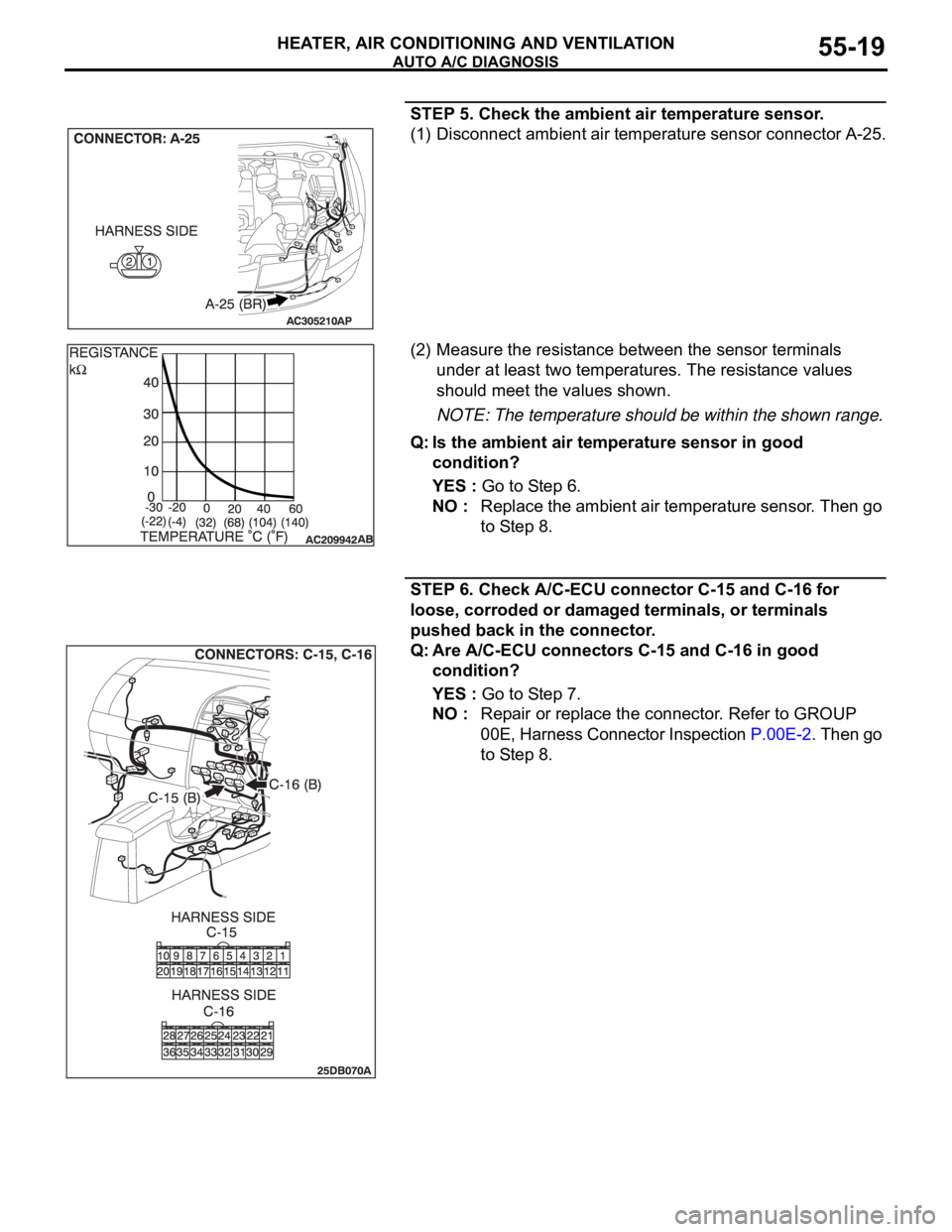
STEP 5. Check the ambient air temperature sensor.
(1) Disconnect ambient air temperature sensor connector A-25.
(2) Measure the resistance between the sensor terminals
under at least two temperatures. The resistance values
should meet the values shown.
NOTE: The temperature should be within the shown range.
Q: Is the ambient air temperature sensor in good
condition?
YES : Go to Step 6.
NO : Replace the ambient air temperature sensor. Then go
to Step 8.
STEP 6. Check A/C-ECU connector C-15 and C-16 for
loose, corroded or damaged terminals, or terminals
pushed back in the connector.
Q: Are A/C-ECU connectors C-15 and C-16 in good
condition?
YES : Go to Step 7.
NO : Repair or replace the connector. Refer to GROUP
00E, Harness Connector Inspection P.00E-2. Then go
to Step 8.
Page 721 of 1500
AUTO A/C DIAGNOSIS
HEATER, AIR CONDITIONING AND VENTILATION55-20
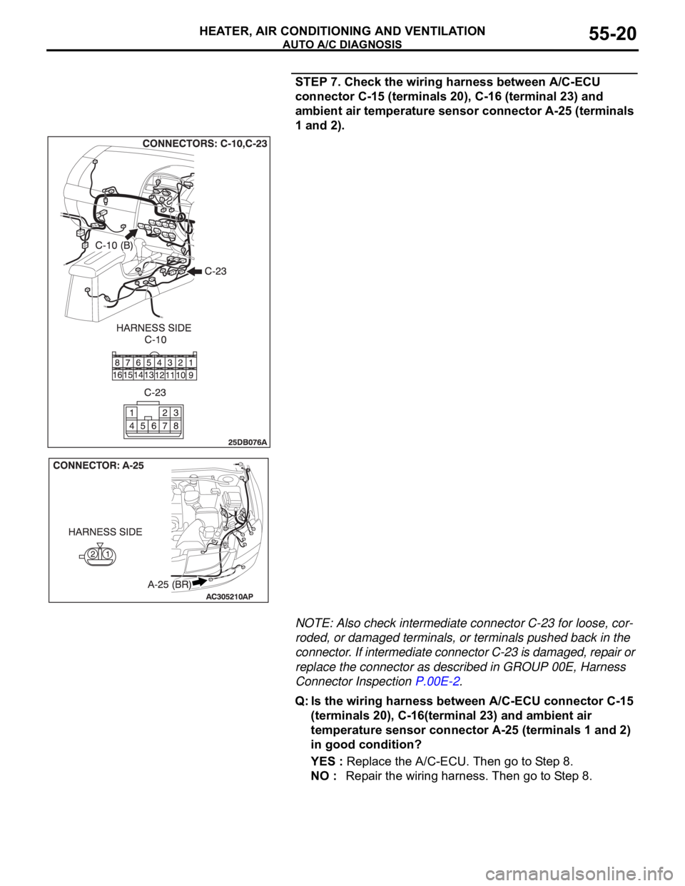
STEP 7. Check the wiring harness between A/C-ECU
connector C-15 (terminals 20), C-16 (terminal 23) and
ambient air temperature sensor connector A-25 (terminals
1 and 2).
NOTE: Also check intermediate connector C-23 for loose, cor-
roded, or damaged terminals, or terminals pushed back in the
connector. If intermediate connector C-23 is damaged, repair or
replace the connector as described in GROUP 00E, Harness
Connector Inspection P.00E-2.
Q: Is the wiring harness between A/C-ECU connector C-15
(terminals 20), C-16(terminal 23) and ambient air
temperature sensor connector A-25 (terminals 1 and 2)
in good condition?
YES : Replace the A/C-ECU. Then go to Step 8.
NO : Repair the wiring harness. Then go to Step 8.
Page 725 of 1500
AUTO A/C DIAGNOSIS
HEATER, AIR CONDITIONING AND VENTILATION55-24
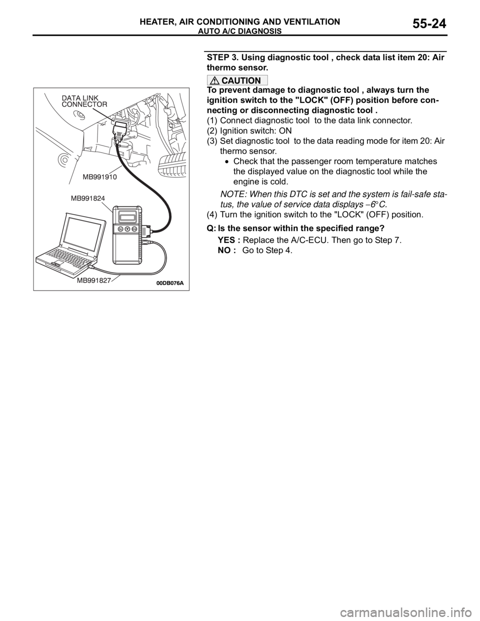
STEP 3. Using diagnostic tool , check data list item 20: Air
thermo sensor.
To prevent damage to diagnostic tool , always turn the
ignition switch to the "LOCK" (OFF) position before con-
necting or disconnecting diagnostic tool .
(1) Connect diagnostic tool to the data link connector.
(2) Ignition switch: ON
(3) Set diagnostic tool to the data reading mode for item 20: Air
thermo sensor.
Check that the passenger room temperature matches
the displayed value on the diagnostic tool while the
engine is cold.
NOTE: When this DTC is set and the system is fail-safe sta-
tus, the value of service data displays
6C.
(4) Turn the ignition switch to the "LOCK" (OFF) position.
Q: Is the sensor within the specified range?
YES : Replace the A/C-ECU. Then go to Step 7.
NO : Go to Step 4.
Page 728 of 1500
AUTO A/C DIAGNOSIS
HEATER, AIR CONDITIONING AND VENTILATION55-27
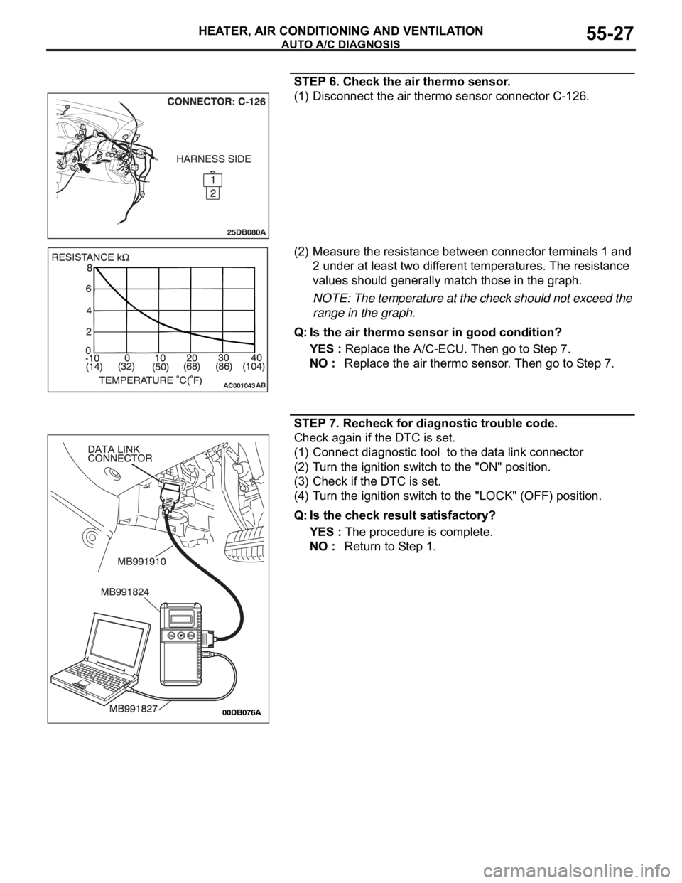
STEP 6. Check the air thermo sensor.
(1) Disconnect the air thermo sensor connector C-126.
(2) Measure the resistance between connector terminals 1 and
2 under at least two different temperatures. The resistance
values should generally match those in the graph.
NOTE: The temperature at the check should not exceed the
range in the graph.
Q: Is the air thermo sensor in good condition?
YES : Replace the A/C-ECU. Then go to Step 7.
NO : Replace the air thermo sensor. Then go to Step 7.
STEP 7. Recheck for diagnostic trouble code.
Check again if the DTC is set.
(1) Connect diagnostic tool to the data link connector
(2) Turn the ignition switch to the "ON" position.
(3) Check if the DTC is set.
(4) Turn the ignition switch to the "LOCK" (OFF) position.
Q: Is the check result satisfactory?
YES : The procedure is complete.
NO : Return to Step 1.
Page 776 of 1500
AUTO A/C DIAGNOSIS
HEATER, AIR CONDITIONING AND VENTILATION55-75
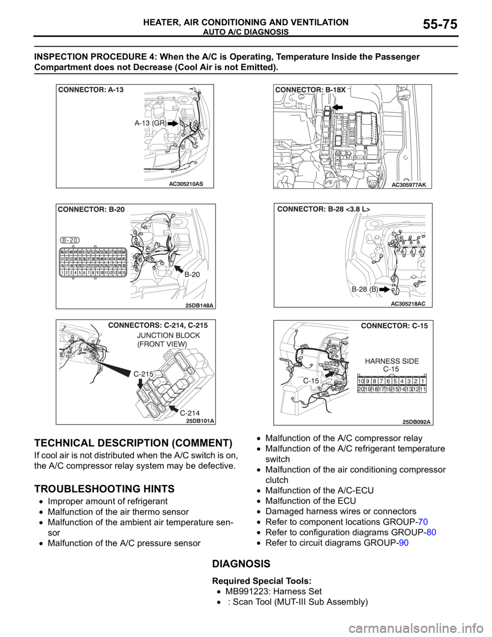
INSPECTION PROCEDURE 4: When the A/C is Operating, Temperature Inside the Passenger
Compartment does not Decrease (Cool Air is not Emitted).
.
TECHNICAL DESCRIPTION (COMMENT)
If cool air is not distributed when the A/C switch is on,
the A/C compressor relay system may be defective.
.
TROUBLESHOOTING HINTS
Improper amount of refrigerant
Malfunction of the air thermo sensor
Malfunction of the ambient air temperature sen-
sor
Malfunction of the A/C pressure sensor
Malfunction of the A/C compressor relay
Malfunction of the A/C refrigerant temperature
switch
Malfunction of the air conditioning compressor
clutch
Malfunction of the A/C-ECU
Malfunction of the ECU
Damaged harness wires or connectors
Refer to component locations GROUP-70
Refer to configuration diagrams GROUP-80
Refer to circuit diagrams GROUP-90
DIAGNOSIS
Required Special Tools:
MB991223: Harness Set
: Scan Tool (MUT-III Sub Assembly)
Page 788 of 1500
AUTO A/C DIAGNOSIS
HEATER, AIR CONDITIONING AND VENTILATION55-87
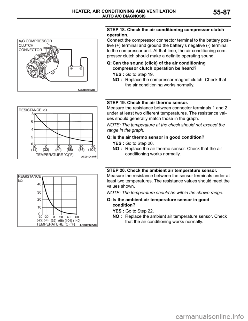
STEP 18. Check the air conditioning compressor clutch
operation.
Connect the compressor connector terminal to the battery posi-
tive (+) terminal and ground the battery’s negative (-) terminal
to the compressor unit. At that time, the air conditioning com-
pressor clutch should make a definite operating sound.
Q: Can the sound (click) of the air conditioning
compressor clutch operation be heard?
YES : Go to Step 19.
NO : Replace the compressor magnet clutch. Check that
the air conditioning works normally.
STEP 19. Check the air thermo sensor.
Measure the resistance between connector terminals 1 and 2
under at least two different temperatures. The resistance val-
ues should generally match those in the graph.
NOTE: The temperature at the check should not exceed the
range in the graph.
Q: Is the air thermo sensor in good condition?
YES : Go to Step 20.
NO : Replace the air thermo sensor. Check that the air
conditioning works normally.
STEP 20. Check the ambient air temperature sensor.
Measure the resistance between the sensor terminals under at
least two temperatures. The resistance values should meet the
values shown.
NOTE: The temperature should be within the shown range.
Q: Is the ambient air temperature sensor in good
condition?
YES : Go to Step 22.
NO : Replace the ambient air temperature sensor. Check
that the air conditioning works normally.