AC temperature sensor MITSUBISHI 380 2005 Owner's Manual
[x] Cancel search | Manufacturer: MITSUBISHI, Model Year: 2005, Model line: 380, Model: MITSUBISHI 380 2005Pages: 1500, PDF Size: 47.87 MB
Page 805 of 1500
AUTO A/C DIAGNOSIS
HEATER, AIR CONDITIONING AND VENTILATION55-104
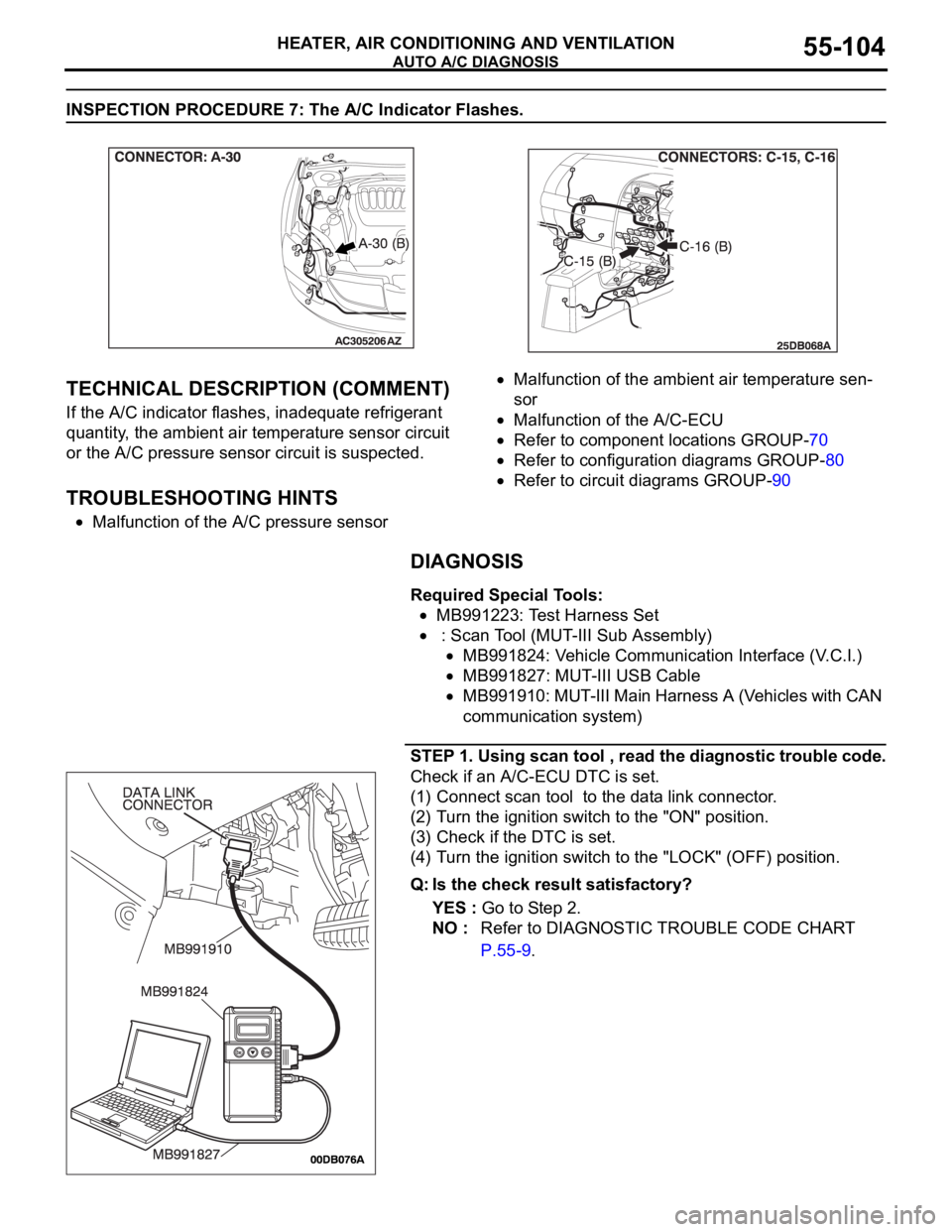
INSPECTION PROCEDURE 7: The A/C Indicator Flashes.
.
TECHNICAL DESCRIPTION (COMMENT)
If the A/C indicator flashes, inadequate refrigerant
quantity, the ambient air temperature sensor circuit
or the A/C pressure sensor circuit is suspected.
.
TROUBLESHOOTING HINTS
Malfunction of the A/C pressure sensor
Malfunction of the ambient air temperature sen-
sor
Malfunction of the A/C-ECU
Refer to component locations GROUP-70
Refer to configuration diagrams GROUP-80
Refer to circuit diagrams GROUP-90
DIAGNOSIS
Required Special Tools:
MB991223: Test Harness Set
: Scan Tool (MUT-III Sub Assembly)
MB991824: Vehicle Communication Interface (V.C.I.)
MB991827: MUT-III USB Cable
MB991910: MUT-III Main Harness A (Vehicles with CAN
communication system)
STEP 1. Using scan tool , read the diagnostic trouble code.
Check if an A/C-ECU DTC is set.
(1) Connect scan tool to the data link connector.
(2) Turn the ignition switch to the "ON" position.
(3) Check if the DTC is set.
(4) Turn the ignition switch to the "LOCK" (OFF) position.
Q: Is the check result satisfactory?
YES : Go to Step 2.
NO : Refer to DIAGNOSTIC TROUBLE CODE CHART
P.55-9.
Page 829 of 1500
AUTO A/C DIAGNOSIS
HEATER, AIR CONDITIONING AND VENTILATION55-128
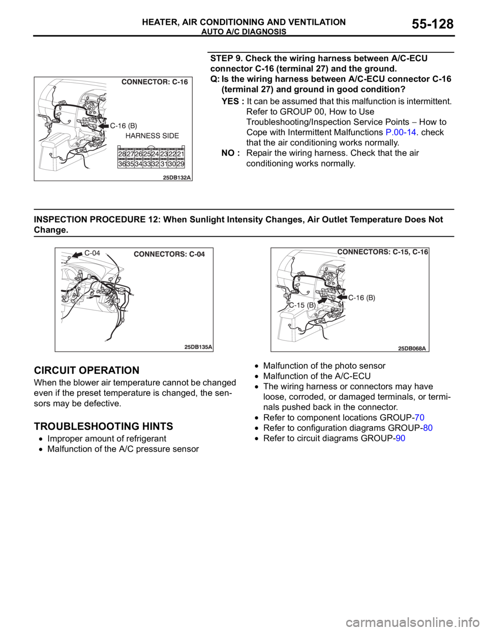
STEP 9. Check the wiring harness between A/C-ECU
connector C-16 (terminal 27) and the ground.
Q: Is the wiring harness between A/C-ECU connector C-16
(terminal 27) and ground in good condition?
YES : It can be assumed that this malfunction is intermittent.
Refer to GROUP 00, How to Use
Troubleshooting/Inspection Service Points
How to
Cope with Intermittent Malfunctions P.00-14. check
that the air conditioning works normally.
NO : Repair the wiring harness. Check that the air
conditioning works normally.
INSPECTION PROCEDURE 12: When Sunlight Intensity Changes, Air Outlet Temperature Does Not
Change.
.
CIRCUIT OPERATION
When the blower air temperature cannot be changed
even if the preset temperature is changed, the sen-
sors may be defective.
.
TROUBLESHOOTING HINTS
Improper amount of refrigerant
Malfunction of the A/C pressure sensor
Malfunction of the photo sensor
Malfunction of the A/C-ECU
The wiring harness or connectors may have
loose, corroded, or damaged terminals, or termi-
nals pushed back in the connector.
Refer to component locations GROUP-70
Refer to configuration diagrams GROUP-80
Refer to circuit diagrams GROUP-90
Page 834 of 1500

AUTO A/C DIAGNOSIS
HEATER, AIR CONDITIONING AND VENTILATION55-133
DATA LIST REFERENCE TABLEM1554005100136
MUT-III
DIAGNOSTIC
TOOL DISPLAYITEM
NO.INSPECTION ITEM INSPECTION REQUIREMENT NORMAL VALUE
Inside
temperature
sensor59 Interior temperature
sensorIgnition switch: ON Inside air
temperature and
temperature
displayed on the
diagnostic tool are
identical.
Outside
temperature
sensor58 Outside temperature
sensorIgnition switch: ON Outside air
temperature and
temperature
displayed on the
diagnostic tool are
identical.
Air thermo sensor 20 Air thermo sensor Ignition switch: ON The temperature
measured behind
the evaporator
matches the
displayed value on
the diagnostic tool
while the engine is
cold.
Pressure sensor 61 A/C pressure sensor Ignition switch: ON Measured refrigerant
pressure is nearly
equal to the value
shown on the
diagnostic tool
(MPa).
Water
temperature
sensor62 Engine coolant
temperature sensor
(Data received by
CAN
Communication)Ignition switch: ON Engine coolant
temperature and
temperature
displayed on the
diagnostic tool are
identical.
Photo sensor 67 Photo sensor Ignition switch: ON Amount of light is
proportional to
voltage displayed on
the diagnostic tool.
Air mix
potentiometer63 Air mixing damper
control motor
potentiometerIgnition switch: ON Damper
positionOpening degree (V)
MAX. HOT Approx. 5
MAX. COOL Approx. 0
Air mix
potentiometer
(Target)64 Target value for air
mixing damper
control motor
potentiometerIgnition switch: ON Damper
positionOpening degree (V)
MAX. HOT Approx. 5
MAX. COOL Approx. 0
Page 839 of 1500

AUTO A/C DIAGNOSIS
HEATER, AIR CONDITIONING AND VENTILATION55-138
16 Potentiometer power supply Ignition switch: ON 5 V
17 Power transistor (BASE) When the blower speed
selection dial shows Maximum
air volume.1 V
18 Power transistor
(COLLECTOR)When the blower speed
selection dial shows Maximum
air volume.12.1 V
19 Photo sensor Ignition switch: ON 5 V
20 Sensors and potentiometers
groundAlways 0 V
21 Mode selection damper control
motor potentiometer inputWhen the damper is moved to
the FACE position. 4 V
22 Interior temperature sensor Ignition switch: ON 5 V
23 Ambient temperature sensor
inputWhen sensor temperature is
25
C (77F) [4 k]1.9 V
24 Air thermo sensor input When sensor temperature is
25
C (77F) [1.5 k]2.2 V
25 Photo sensor ground Ignition switch: ON 0 V
26 A/C pressure sensor at 2.6 MPa 3.9 V
27 Ground Always 0 V
28 Power supply to the ignition
switch (IG2)Ignition switch: ON Battery positive voltage
29 Air mixing damper control motor
potentiometer inputWhen the damper door is
moved to the MAX. HOT
position.1.4 V
30 Illumination ground Always 0 V
31 ILL power supply Lighting switch: ON Battery positive voltage
34 A/C pressure sensor ground Always 0 V
36 Power supply to the ignition
switch (ACC)Ignition switch: ON Battery positive voltage TERMINAL
NO.CHECK ITEM CHECKING REQUIREMENTS NORMAL CONDITION
Page 843 of 1500

ON-VEHICLE SERVICE
HEATER, AIR CONDITIONING AND VENTILATION55-142
4. At this time, check to see that the voltage of A/C pressure
sensor terminal No. 2 reflects the specifications of the fig-
ure.
NOTE: The allowance shall be defined as
5%.
COMPRESSOR DRIVE BELT ADJUSTMENTM1552001000357
Refer to GROUP 00, Maintenance Service Drive Belts
P.00-39.
CHARGING M1552001200403
Use the refrigerant recovery station to charge the refrigerant.
METHOD BY USING REFRIGERANT RECOVERY
AND RECYCLING UNIT
Using the refrigerant recovery and recycling unit, refill the
refrigerant.
NOTE: Refer to the Refrigerant Recovery and Recycling Unit’s
Instruction Manual for operation of the unit.
DISCHARGING SYSTEM
Use the refrigerant recovery unit to discharge refrigerant gas
from the system.
NOTE: Refer to the Refrigerant Recovery and Recycling Unit’s
Instruction Manual for operation of the unit.
REFILLING OF OIL IN THE A/C SYSTEM
Too little oil will provide inadequate compressor lubrication and
cause a compressor failure. Too much oil will increase dis-
charge air temperature.
When a compressor is installed at the factory, it contains 140
ml of refrigerant oil. While the A/C system is in operation, the oil
is carried through the entire system by the refrigerant. Some of
this oil will be trapped and retained in various parts of the sys-
tem.
When the following system components are changed, it is nec-
essary to add oil to the system to replace the oil being removed
with the component.
Compressor oil: ND Oil 8
Quantity:
Evaporator: 40 ml
Condenser: 40 ml
Page 856 of 1500
HEATER UNIT, HEATER CORE, BLOWER ASSEMBLY AND EVAPORATOR UNIT
HEATER, AIR CONDITIONING AND VENTILATION55-155
INSPECTIONM1552014301157.
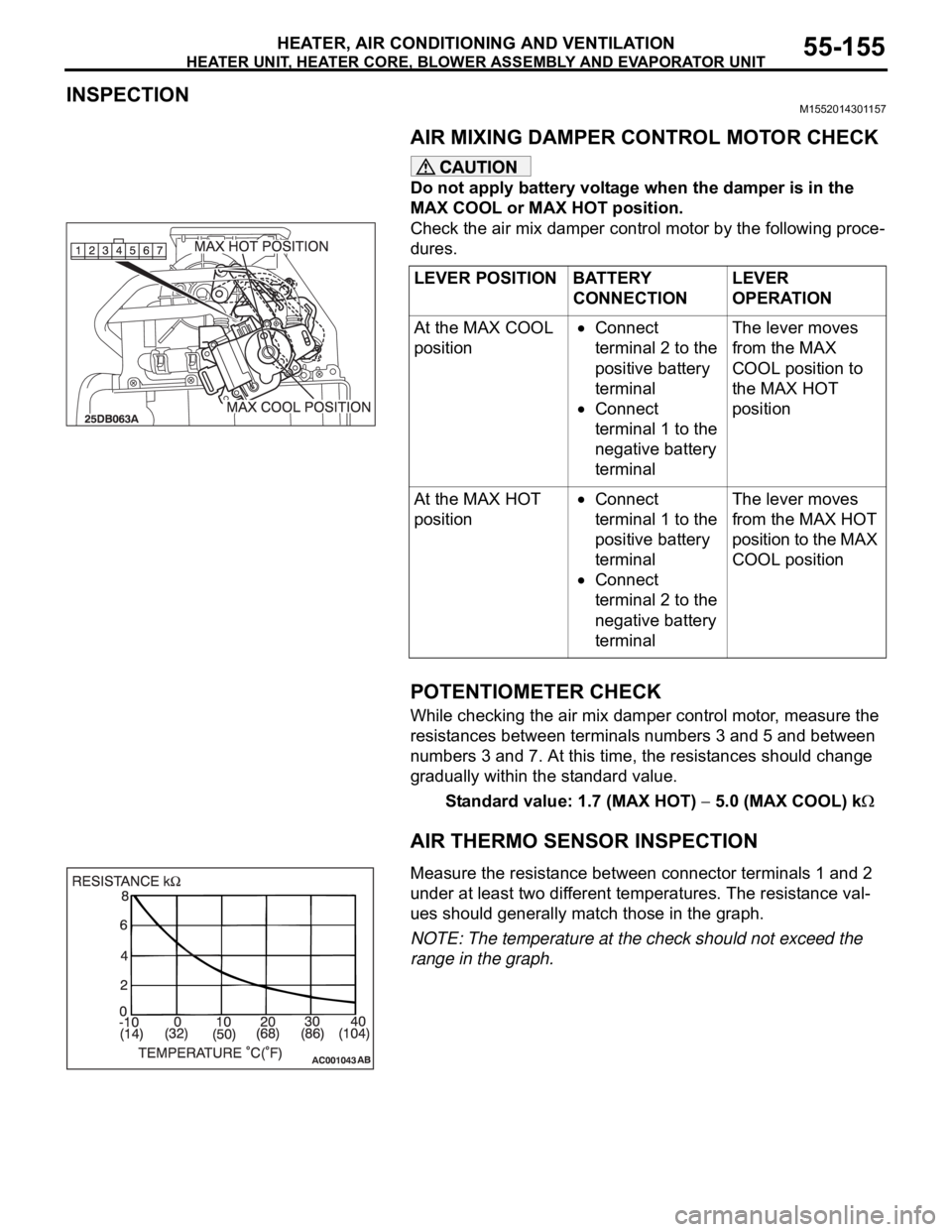
AIR MIXING DAMPER CONTROL MOTOR CHECK
Do not apply battery voltage when the damper is in the
MAX COOL or MAX HOT position.
Check the air mix damper control motor by the following proce-
dures.
.
POTENTIOMETER CHECK
While checking the air mix damper control motor, measure the
resistances between terminals numbers 3 and 5 and between
numbers 3 and 7. At this time, the resistances should change
gradually within the standard value.
Standard value: 1.7 (MAX HOT)
5.0 (MAX COOL) k
AIR THERMO SENSOR INSPECTION
.Measure the resistance between connector terminals 1 and 2
under at least two different temperatures. The resistance val-
ues should generally match those in the graph.
NOTE: The temperature at the check should not exceed the
range in the graph. LEVER POSITION BATTERY
CONNECTIONLEVER
OPERATION
At the MAX COOL
position
Connect
terminal 2 to the
positive battery
terminal
Connect
terminal 1 to the
negative battery
terminalThe lever moves
from the MAX
COOL position to
the MAX HOT
position
At the MAX HOT
position
Connect
terminal 1 to the
positive battery
terminal
Connect
terminal 2 to the
negative battery
terminalThe lever moves
from the MAX HOT
position to the MAX
COOL position
Page 861 of 1500
SENSORS
HEATER, AIR CONDITIONING AND VENTILATION55-160
SENSORS
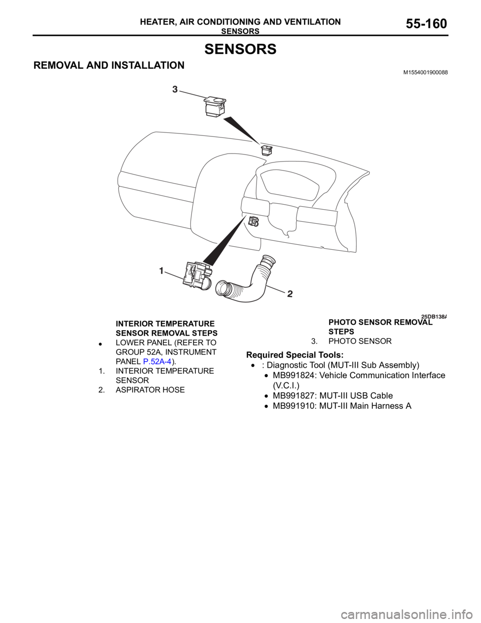
REMOVAL AND INSTALLATIONM1554001900088
Required Special Tools:
: Diagnostic Tool (MUT-III Sub Assembly)
MB991824: Vehicle Communication Interface
(V.C.I.)
MB991827: MUT-III USB Cable
MB991910: MUT-III Main Harness A
INTERIOR TEMPERATURE
SENSOR REMOVAL STEPS
LOWER PANEL (REFER TO
GROUP 52A, INSTRUMENT
PA N E L P.52A-4).
1. INTERIOR TEMPERATURE
SENSOR
2. ASPIRATOR HOSEPHOTO SENSOR REMOVAL
STEPS
3. PHOTO SENSOR
Page 862 of 1500
SENSORS
HEATER, AIR CONDITIONING AND VENTILATION55-161
INSPECTIONM1554002000130.
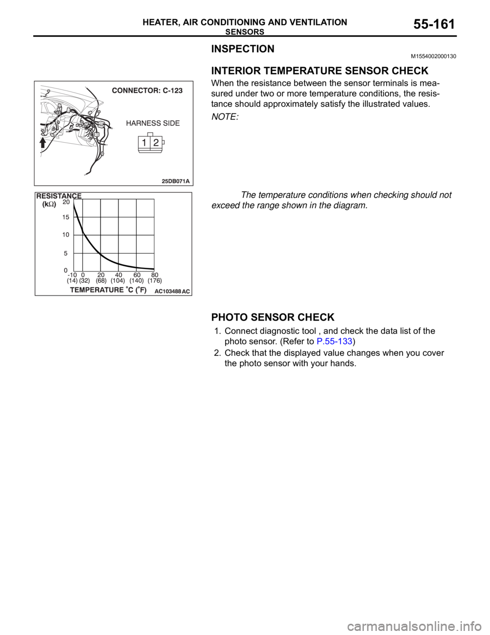
INTERIOR TEMPERATURE SENSOR CHECK
When the resistance between the sensor terminals is mea-
sured under two or more temperature conditions, the resis-
tance should approximately satisfy the illustrated values.
NOTE:
The temperature conditions when checking should not
exceed the range shown in the diagram.
.
PHOTO SENSOR CHECK
1. Connect diagnostic tool , and check the data list of the
photo sensor. (Refer to P.55-133)
2. Check that the displayed value changes when you cover
the photo sensor with your hands.
Page 863 of 1500
AMBIENT TEMPERATURE SENSOR
HEATER, AIR CONDITIONING AND VENTILATION55-162
AMBIENT TEMPERATURE SENSOR
REMOVAL AND INSTALLATIONM1554003400108
REMOVAL SERVICE POINT
.
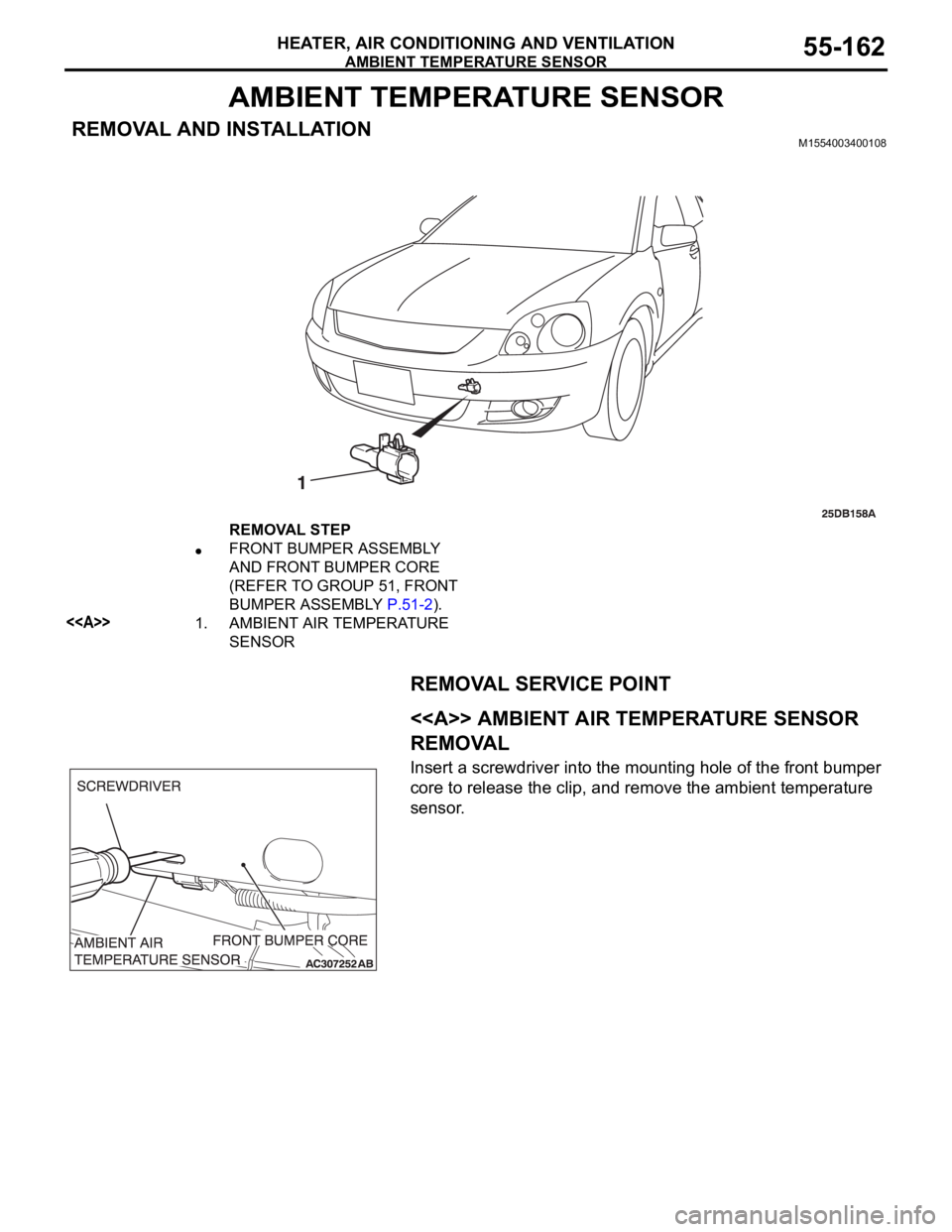
<> AMBIENT AIR TEMPERATURE SENSOR
REMOVAL
Insert a screwdriver into the mounting hole of the front bumper
core to release the clip, and remove the ambient temperature
sensor.
REMOVAL STEP
FRONT BUMPER ASSEMBLY
AND FRONT BUMPER CORE
(REFER TO GROUP 51, FRONT
BUMPER ASSEMBLY P.51-2).
<>1. AMBIENT AIR TEMPERATURE
SENSOR
Page 864 of 1500
AMBIENT TEMPERATURE SENSOR
HEATER, AIR CONDITIONING AND VENTILATION55-163
INSPECTIONM1551006300349.
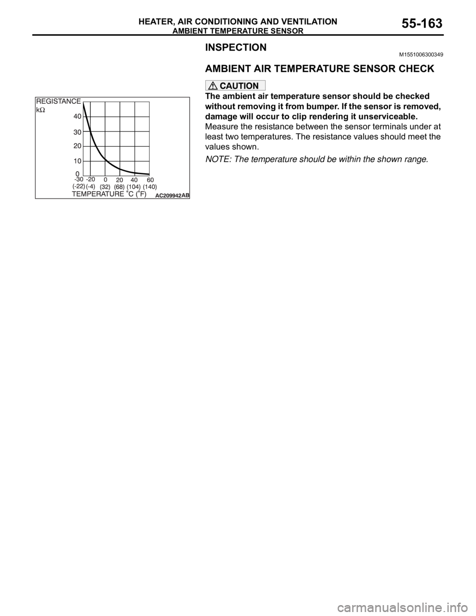
AMBIENT AIR TEMPERATURE SENSOR CHECK
The ambient air temperature sensor should be checked
without removing it from bumper. If the sensor is removed,
damage will occur to clip rendering it unserviceable.
Measure the resistance between the sensor terminals under at
least two temperatures. The resistance values should meet the
values shown.
NOTE: The temperature should be within the shown range.