AC temperature sensor MITSUBISHI 380 2005 Owner's Guide
[x] Cancel search | Manufacturer: MITSUBISHI, Model Year: 2005, Model line: 380, Model: MITSUBISHI 380 2005Pages: 1500, PDF Size: 47.87 MB
Page 887 of 1500
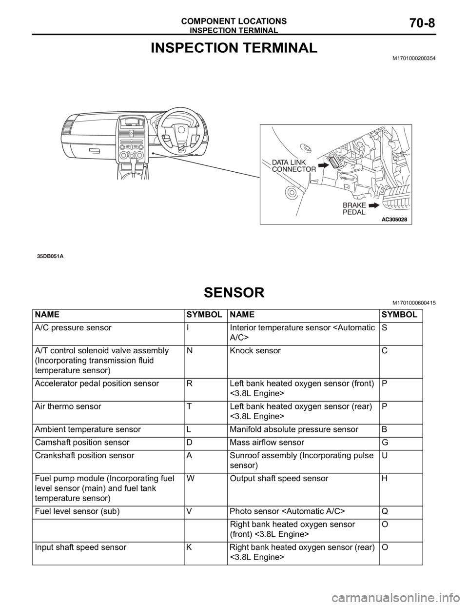
INSPECTION TERMINAL
COMPONENT LOCATIONS70-8
INSPECTION TERMINALM1701000200354
SENSORM1701000600415
NAME SYMBOL NAME SYMBOL
A/C pressure sensor I Interior temperature sensor
A/T control solenoid valve assembly
(Incorporating transmission fluid
temperature sensor)N Knock sensor C
Accelerator pedal position sensor R Left bank heated oxygen sensor (front)
<3.8L Engine>P
Air thermo sensor T Left bank heated oxygen sensor (rear)
<3.8L Engine>P
Ambient temperature sensor L Manifold absolute pressure sensor B
Camshaft position sensor D Mass airflow sensor G
Crankshaft position sensor A Sunroof assembly (Incorporating pulse
sensor)U
Fuel pump module (Incorporating fuel
level sensor (main) and fuel tank
temperature sensor)W Output shaft speed sensor H
Fuel level sensor (sub) V Photo sensor
Right bank heated oxygen sensor
(front) <3.8L Engine>O
Input shaft speed sensor K Right bank heated oxygen sensor (rear)
<3.8L Engine>O
Page 888 of 1500
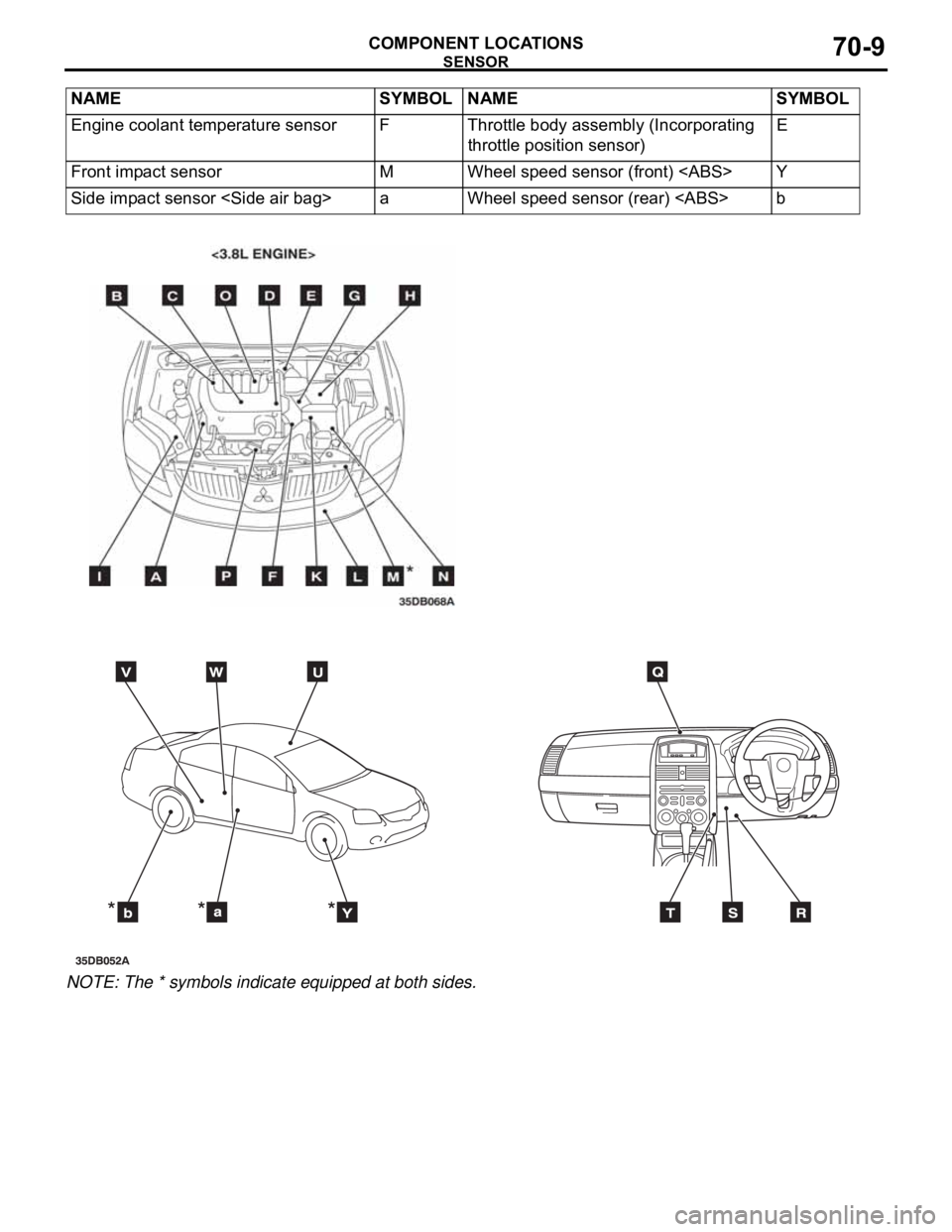
SENSOR
COMPONENT LOCATIONS70-9
NOTE: The * symbols indicate equipped at both sides.Engine coolant temperature sensor F Throttle body assembly (Incorporating
throttle position sensor)E
Front impact sensor M Wheel speed sensor (front)
Side impact sensor
Page 920 of 1500

ENGINE COOLING DIAGNOSIS
ENGINE COOLING14-5
INSPECTION PROCEDURE 3: Radiator Fan and Condenser Fan do not Operate
.
CIRCUIT OPERATION
The fan controller is powered from fusible link
No.2.
The engine-ECU uses input signals from the A/C
switch, the water temperature sensor unit and the
vehicle speed sensor
speed sensor to control the speed of the
radiator fan motor and the condenser fan motor.
The engine-ECU controls the fan controller to
activate the radiator fan motor and the condenser
fan motor.
.
TECHNICAL DESCRIPTION
The cause could be a malfunction of the fan con-
troller power supply or earth circuit.
If the communication line wiring harness between
the fan controller and the engine-ECU is
short-circuited to earth, the radiator fan motor
and the condenser fan motor will not rotate.
The cause could also be a malfunction of input
signal from the A/C switch, the water temperature
sensor unit and the vehicle speed sensor
or the output shaft speed sensor to the
engine-ECU.
The cause could also be a malfunction of the fan
controller or the engine-ECU.
.
TROUBLESHOOTING HINTS
Malfunction of fusible link No.2
Malfunction of fan control relay
Malfunction of cooling fan motor and fan control-
ler
Malfunction of engine-ECU.
Damaged wiring harness or connector
Refer to component locations GROUP-1
Refer to configuration diagrams GROUP-1
Refer to circuit diagrams GROUP-1
Page 935 of 1500
ENGINE COOLING DIAGNOSIS
ENGINE COOLING14-20
STEP 23. MUT-III self-diag code
Check if an MPI system self-diag code is set. (Refer to GROUP
13A - Trouble shooting 13A-5).
Q: Diagnosis code set?
YES : Inspection chart for diagnosis code (Refer to GROUP
13A - Trouble shooting 13A-17)
NO : Replace the engine-ECU (Refer to GROUP 13A,
Engine-ECU 13A-675 ). Then go to Step 24.
STEP 24. Check the symptoms.
Q: Does the radiator fan motor and the condenser fan
motor operate correctly?
YES : This symptom is complete.
NO : Return to Step 1.
INSPECTION PROCEDURE 4: Radiator Fan and Condenser Fan do not Change Speed or Stop
.
Radiator Fan and Condenser Fan Drive
Circuit
Refer to 5.
.
TECHNICAL DESCRIPTION
The cause could be a malfunction of the fan con-
troller power supply or earth circuit.
If the communication line wiring harness between
the fan controller and the engine-ECU is
short-circuited to earth, the radiator fan motor
and the condenser fan motor will not rotate.
The cause could also be a malfunction of input
signal from the A/C switch, the water temperature
sensor unit and the vehicle speed sensor
or the output shaft speed sensor to the
engine-ECU.
The cause could also be a malfunction of the fan
controller or the engine-ECU.
.
TROUBLESHOOTING HINTS
Malfunction of fusible link No.2
Malfunction of fan control relay
Malfunction of cooling fan motor
Malfunction of fan controller
Malfunction of engine-ECU
Damaged wiring harness or connector
DIAGNOSIS
STEP 1. Check the fan control relay.
Refer to 14-31.
Q: Is the fan control relay in good condition?
YES : Go to Step 2.
NO : Replace the fan control relay. Then go to Step 8.
Page 951 of 1500
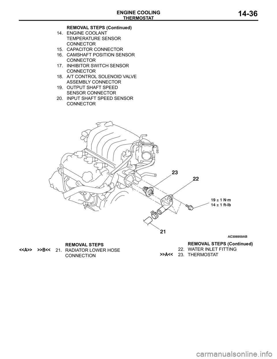
THERMOSTAT
ENGINE COOLING14-36
14. ENGINE COOLANT
TEMPERATURE SENSOR
CONNECTOR
15. CAPACITOR CONNECTOR
16. CAMSHAFT POSITION SENSOR
CONNECTOR
17. INHIBITOR SWITCH SENSOR
CONNECTOR
18. A/T CONTROL SOLENOID VALVE
ASSEMBLY CONNECTOR
19. OUTPUT SHAFT SPEED
SENSOR CONNECTOR
20. INPUT SHAFT SPEED SENSOR
CONNECTOR REMOVAL STEPS (Continued)
REMOVAL STEPS
<> >>B<<21. RADIATOR LOWER HOSE
CONNECTION22. WATER INLET FITTING>>A<<23. THERMOSTATREMOVAL STEPS (Continued)
Page 955 of 1500
WATER HOSE AND WATER PIPE
ENGINE COOLING14-40
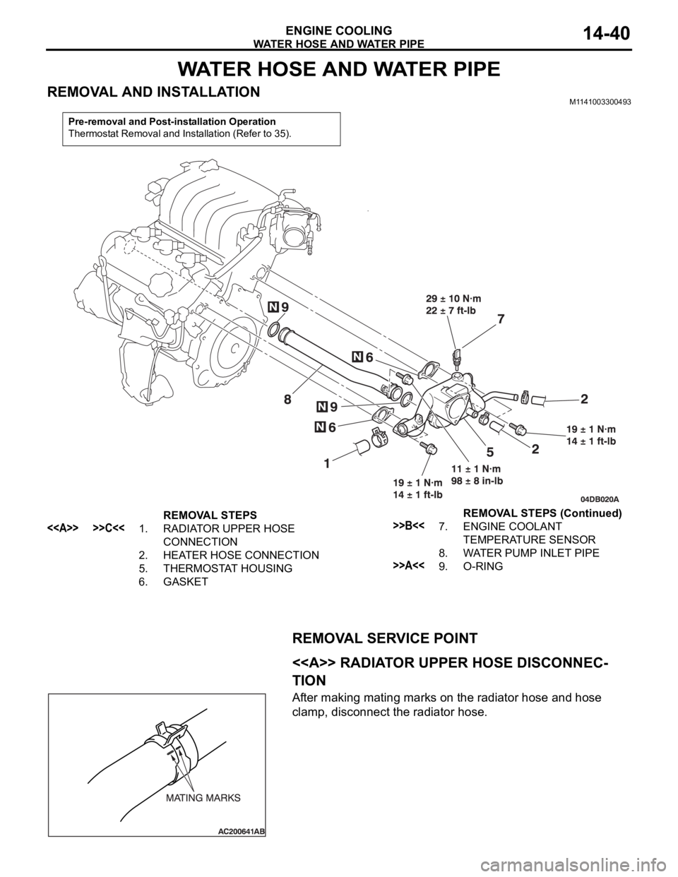
WATER HOSE AND WATER PIPE
REMOVAL AND INSTALLATIONM1141003300493
REMOVAL SERVICE POINT
.
<> RADIATOR UPPER HOSE DISCONNEC-
TION
After making mating marks on the radiator hose and hose
clamp, disconnect the radiator hose.
Pre-removal and Post-installation Operation
Thermostat Removal and Installation (Refer to 35).
REMOVAL STEPS
<> >>C<<1. RADIATOR UPPER HOSE
CONNECTION
2. HEATER HOSE CONNECTION
5. THERMOSTAT HOUSING
6. GASKET>>B<<7. ENGINE COOLANT
TEMPERATURE SENSOR
8. WATER PUMP INLET PIPE
>>A<<9. O-RINGREMOVAL STEPS (Continued)
Page 956 of 1500
WATER HOSE AND WATER PIPE
ENGINE COOLING14-41
INSTALLATION SERVICE POINTS
.
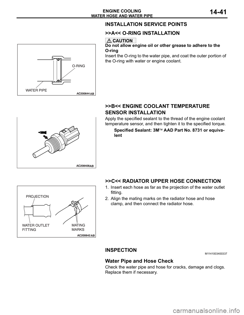
>>A<< O-RING INSTALLATION
Do not allow engine oil or other grease to adhere to the
O-ring
Insert the O-ring to the water pipe, and coat the outer portion of
the O-ring with water or engine coolant.
.
>>B<< ENGINE COOLANT TEMPERATURE
SENSOR INSTALLATION
Apply the specified sealant to the thread of the engine coolant
temperature sensor, and then tighten it to the specified torque.
Specified Sealant: 3M
AAD Part No. 8731 or equiva-
lent
.
>>C<< RADIATOR UPPER HOSE CONNECTION
1. Insert each hose as far as the projection of the water outlet
fitting.
2. Align the mating marks on the radiator hose and hose
clamp, and then connect the radiator hose.
INSPECTIONM1141003400337.
Water Pipe and Hose Check
Check the water pipe and hose for cracks, damage and clogs.
Replace them if necessary.
Page 957 of 1500

SPECIFICATIONS
ENGINE COOLING14-42
SPECIFICATIONS
FASTENER TIGHTENING SPECIFICATIONSM1141005000346
ITEM SPECIFICATION
Cylinder block drain plug 39
5 Nm (29 3 ft-lb)
Radiator
Front end structure bar bolt M8
10 11 2 Nm (98 17 in-lb)
M8
20 22 4 Nm (16 3 ft-lb)
Thermostat
Control harness bolt 5.0
1.0 Nm (44 9 in-lb)
Grounding bolt M6 9.0
2.0 Nm (80 17 in-lb)
M8 22
4 Nm (16 3 ft-lb)
Water inlet fitting bolt 19
1 Nm (14 1 ft-lb)
Water hose and water pipe
Engine coolant temperature sensor 29
10 Nm
Thermostat housing bolt 19
1 Nm (14 1 ft-lb)
Water pump inlet pipe 11
1 Nm (98 8 ft-lb)
Water pump
Water pump bolt M8 42
8 Nm (31 6 ft-lb)
M10 24
3 Nm (18 2 ft-lb)
Water pump bracket bolt 24
3 Nm (18 2 ft-lb)
Page 958 of 1500

SPECIFICATIONS
ENGINE COOLING14-43
SERVICE SPECIFICATIONM1141000300449
CAPACITIESM1141005100138
SEALANTSM1141000500368
ITEM STANDARD VALUE LIMIT
Fan Controller V A/C OFF 1 or less -
A/C ON Repeat
8.2
2.6
System voltage
2.6-
High-pressure valve opening pressure of radiator cap kPa (psi) 93
123 (14 18) Minimum 83 (12)
Thermostat Valve opening temperature
of thermostat
C (F)3.8L Engine 88
1.5 (190 3)
-
Full-opening temperature
of thermostat
C (F)3.8L Engine 100 (212)
-
Valve lift mm (in) 3.8L Engine 9.0 (0.35) or more
-
ITEM
QUANTITY dm3 (qt)
Long life antifreeze coolant or an equivalent 3.8L Engine 8.7 (9.2)
ITEM SPECIFIED SEALANT
Cylinder block drain plug 3M
AAD Part No.8731 or equivalent
Engine coolant temperature sensor
Page 1333 of 1500
ENGINE AND EMISSION CONTROL17-2
EMISSION CONTROL . . . . . . . .17-76
GENERAL DESCRIPTION . . . . . .
17-76
DIAGNOSIS . . . . . . . . . . . . . . . . . .17-76
SPECIAL TOOLS. . . . . . . . . . . . . .17-76
VACUUM HOSES . . . . . . . . . . . . .17-77
VACUUM HOSE ROUTING. . . . . . . . . . 17-77
VACUUM CIRCUIT DIAGRAM . . . . . . . 17-78
VACUUM HOSE INSTALLATION . . . . . 17-78
VACUUM HOSE CHECK. . . . . . . . . . . . 17-79
POSITIVE CRANKCASE VENTILATION
SYSTEM . . . . . . . . . . . . . . . . . . . . .
17-79
GENERAL DESCRIPTION (POSITIVE
CRANKCASE VENTILATION SYSTEM)17-79
COMPONENT LOCATION . . . . . . . . . . 17-80
POSITIVE CRANKCASE VENTILATION
SYSTEM CHECK. . . . . . . . . . . . . . . . . . 17-80
POSITIVE CRANKCASE VENTILATION
VALVE CHECK . . . . . . . . . . . . . . . . . . . 17-80
EVAPORATIVE EMISSION CONTROL SYSTEM . . . . . . . . . . . . . . . . . . . . .
17-81
GENERAL DESCRIPTION (EVAPORATIVE
EMISSION SYSTEM) . . . . . . . . . . . . . . . 17-81
COMPONENT LOCATION . . . . . . . . . . . 17-82
PURGE CONTROL SYSTEM CHECK
(PURGE FLOW CHECK) . . . . . . . . . . . . 17-82
EVAPORATIVE EMISSION PURGE
SOLENOID CHECK . . . . . . . . . . . . . . . . 17-83
MASS AIRFLOW SENSOR CHECK . . . 17-84
ENGINE COOLANT TEMPERATURE
SENSOR CHECK . . . . . . . . . . . . . . . . . . 17-84
INTAKE AIR TEMPERATURE SENSOR
CHECK. . . . . . . . . . . . . . . . . . . . . .17-84
EVAPORATIVE EMISSION CANISTER
. . . . . . . . . . . . . . . . . . . . . . . . . . . .
17-81
REMOVAL AND INSTALLATION . . . . . . 17-81
INSPECTION . . . . . . . . . . . . . . . . . . . . . 17-81
CATALYTIC CONVERTER . . . . . .17-84
GENERAL DESCRIPTION (CATALYTIC
CONVERTER) . . . . . . . . . . . . . . . . . . . . 17-84
SPECIFICATIONS . . . . . . . . . . 17-85
FASTENER TIGHTENING
SPECIFICATIONS . . . . . . . . . . . . . . . . . 17-85