engine MITSUBISHI 380 2005 Workshop Manual
[x] Cancel search | Manufacturer: MITSUBISHI, Model Year: 2005, Model line: 380, Model: MITSUBISHI 380 2005Pages: 1500, PDF Size: 47.87 MB
Page 1367 of 1500
AUTO-CRUISE CONTROL
ENGINE AND EMISSION CONTROL17-36
DIAGNOSIS
Required Special Tools:
MB991958: Diagnostic ToolDiagnostic Tool (MUT-III Sub
Assembly)
MB991824: V.C.I.
MB991827: MUT-III USB Cable
MB991910: MUT-III Main Harness A
MB991223: Harness Set
MB992044: ENGINE-ECU Check Harness
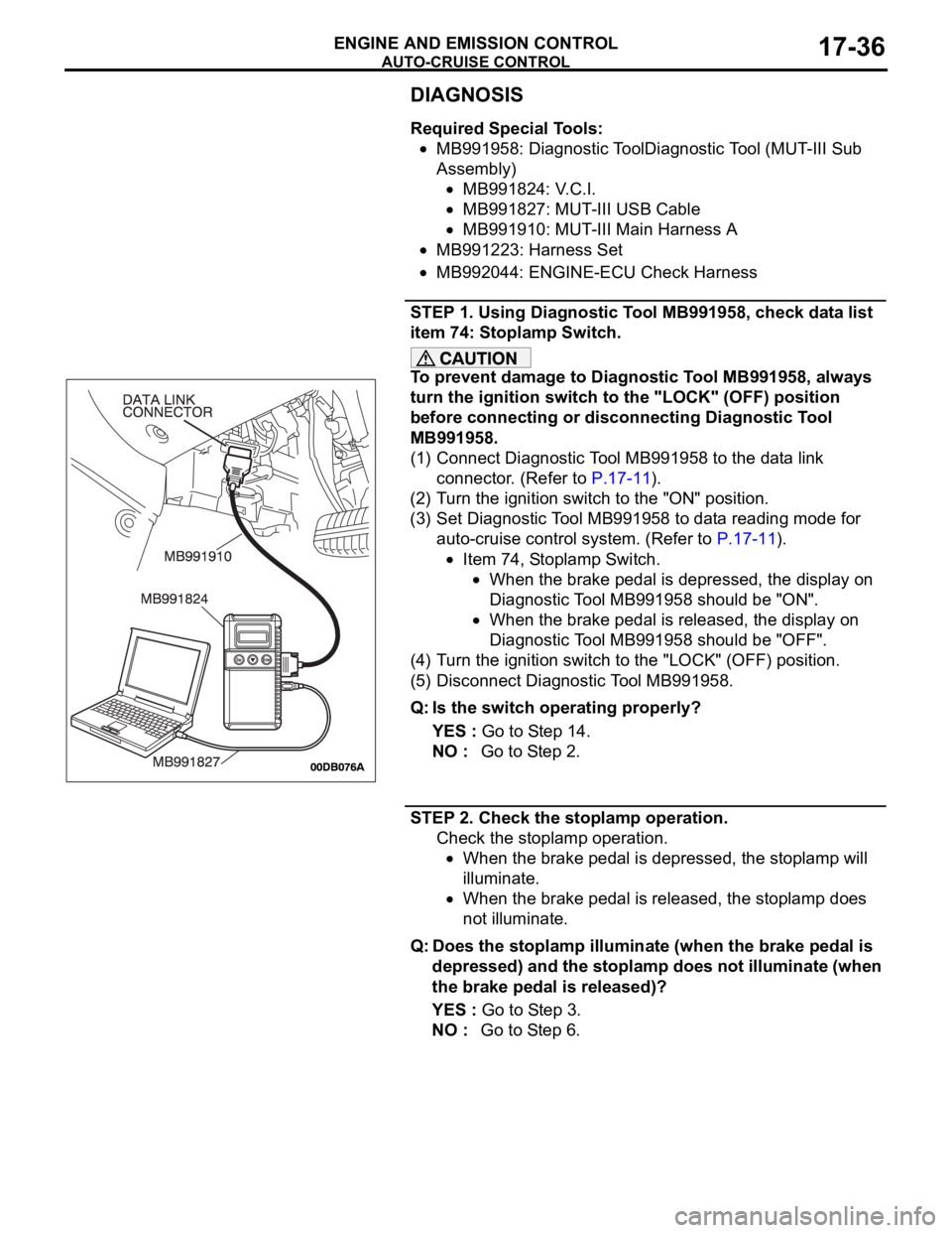
STEP 1. Using Diagnostic Tool MB991958, check data list
item 74: Stoplamp Switch.
To prevent damage to Diagnostic Tool MB991958, always
turn the ignition switch to the "LOCK" (OFF) position
before connecting or disconnecting Diagnostic Tool
MB991958.
(1) Connect Diagnostic Tool MB991958 to the data link
connector. (Refer to P.17-11).
(2) Turn the ignition switch to the "ON" position.
(3) Set Diagnostic Tool MB991958 to data reading mode for
auto-cruise control system. (Refer to P.17-11).
Item 74, Stoplamp Switch.
When the brake pedal is depressed, the display on
Diagnostic Tool MB991958 should be "ON".
When the brake pedal is released, the display on
Diagnostic Tool MB991958 should be "OFF".
(4) Turn the ignition switch to the "LOCK" (OFF) position.
(5) Disconnect Diagnostic Tool MB991958.
Q: Is the switch operating properly?
YES : Go to Step 14.
NO : Go to Step 2.
STEP 2. Check the stoplamp operation.
Check the stoplamp operation.
When the brake pedal is depressed, the stoplamp will
illuminate.
When the brake pedal is released, the stoplamp does
not illuminate.
Q: Does the stoplamp illuminate (when the brake pedal is
depressed) and the stoplamp does not illuminate (when
the brake pedal is released)?
YES : Go to Step 3.
NO : Go to Step 6.
Page 1368 of 1500
AUTO-CRUISE CONTROL
ENGINE AND EMISSION CONTROL17-37
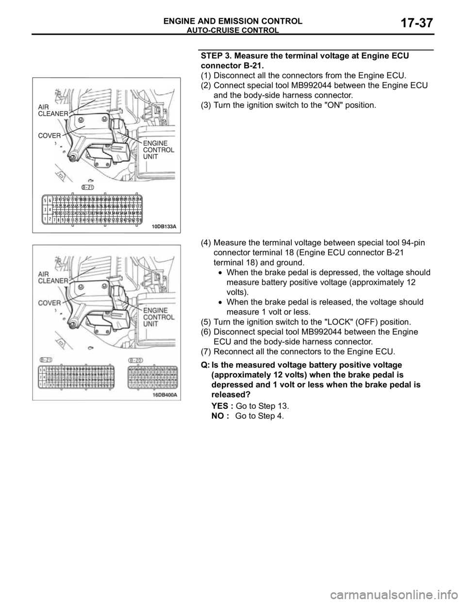
STEP 3. Measure the terminal voltage at Engine ECU
connector B-21.
(1) Disconnect all the connectors from the Engine ECU.
(2) Connect special tool MB992044 between the Engine ECU
and the body-side harness connector.
(3) Turn the ignition switch to the "ON" position.
(4) Measure the terminal voltage between special tool 94-pin
connector terminal 18 (Engine ECU connector B-21
terminal 18) and ground.
When the brake pedal is depressed, the voltage should
measure battery positive voltage (approximately 12
volts).
When the brake pedal is released, the voltage should
measure 1 volt or less.
(5) Turn the ignition switch to the "LOCK" (OFF) position.
(6) Disconnect special tool MB992044 between the Engine
ECU and the body-side harness connector.
(7) Reconnect all the connectors to the Engine ECU.
Q: Is the measured voltage battery positive voltage
(approximately 12 volts) when the brake pedal is
depressed and 1 volt or less when the brake pedal is
released?
YES : Go to Step 13.
NO : Go to Step 4.
Page 1369 of 1500
AUTO-CRUISE CONTROL
ENGINE AND EMISSION CONTROL17-38
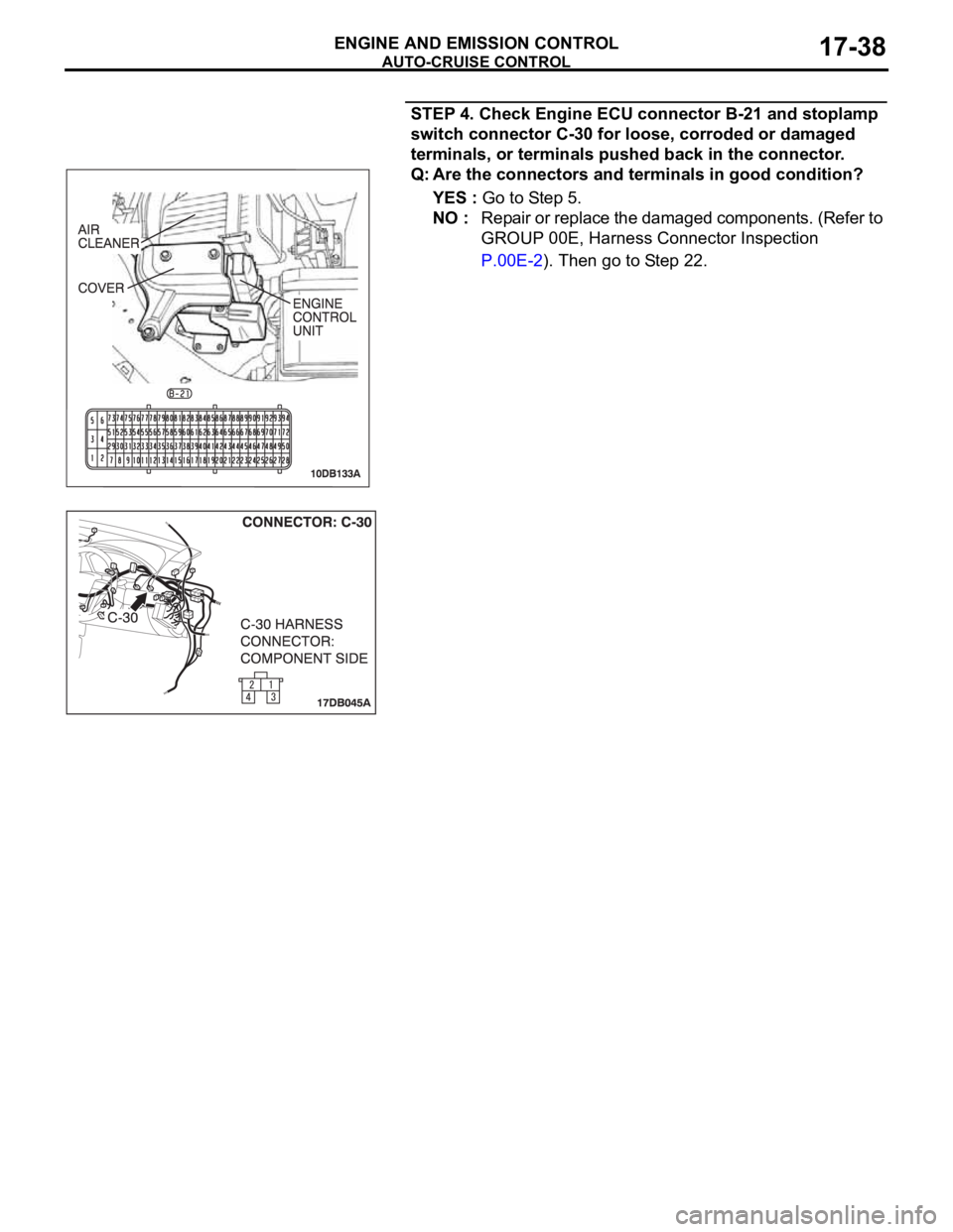
STEP 4. Check Engine ECU connector B-21 and stoplamp
switch connector C-30 for loose, corroded or damaged
terminals, or terminals pushed back in the connector.
Q: Are the connectors and terminals in good condition?
YES : Go to Step 5.
NO : Repair or replace the damaged components. (Refer to
GROUP 00E, Harness Connector Inspection
P.00E-2). Then go to Step 22.
Page 1370 of 1500
AUTO-CRUISE CONTROL
ENGINE AND EMISSION CONTROL17-39
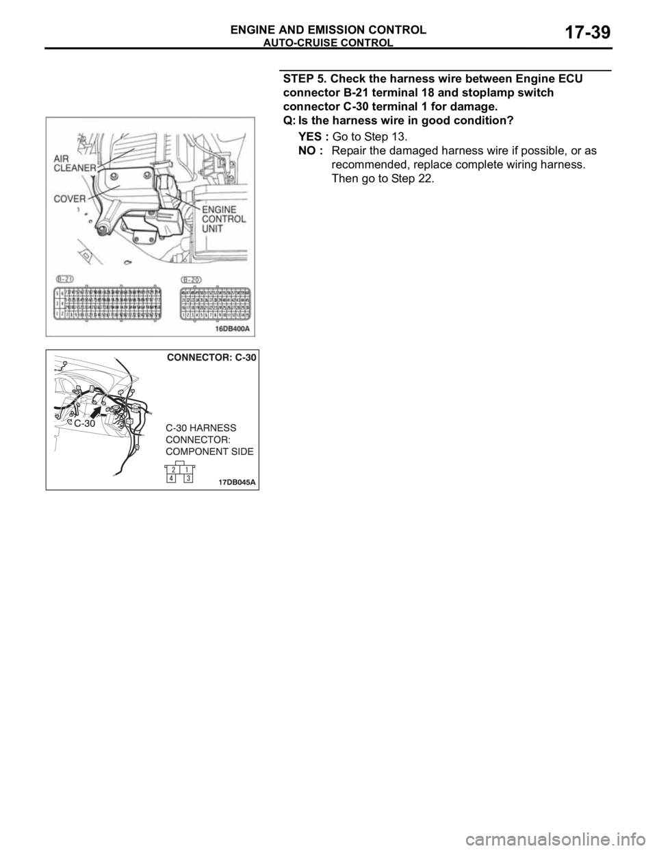
STEP 5. Check the harness wire between Engine ECU
connector B-21 terminal 18 and stoplamp switch
connector C-30 terminal 1 for damage.
Q: Is the harness wire in good condition?
YES : Go to Step 13.
NO : Repair the damaged harness wire if possible, or as
recommended, replace complete wiring harness.
Then go to Step 22.
Page 1371 of 1500
AUTO-CRUISE CONTROL
ENGINE AND EMISSION CONTROL17-40
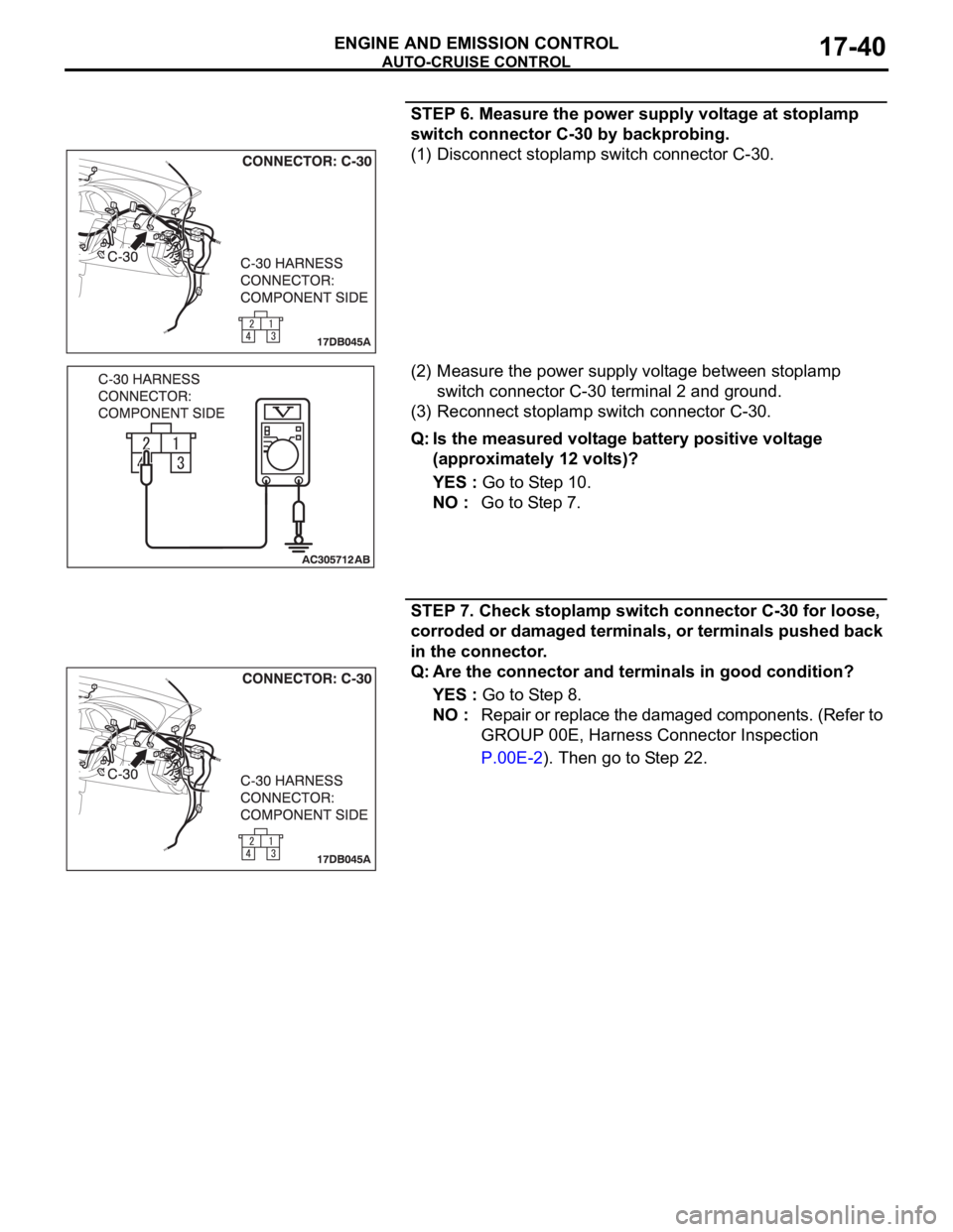
STEP 6. Measure the power supply voltage at stoplamp
switch connector C-30 by backprobing.
(1) Disconnect stoplamp switch connector C-30.
(2) Measure the power supply voltage between stoplamp
switch connector C-30 terminal 2 and ground.
(3) Reconnect stoplamp switch connector C-30.
Q: Is the measured voltage battery positive voltage
(approximately 12 volts)?
YES : Go to Step 10.
NO : Go to Step 7.
STEP 7. Check stoplamp switch connector C-30 for loose,
corroded or damaged terminals, or terminals pushed back
in the connector.
Q: Are the connector and terminals in good condition?
YES : Go to Step 8.
NO : Repair or replace the damaged components. (Refer to
GROUP 00E, Harness Connector Inspection
P.00E-2). Then go to Step 22.
Page 1372 of 1500
AUTO-CRUISE CONTROL
ENGINE AND EMISSION CONTROL17-41
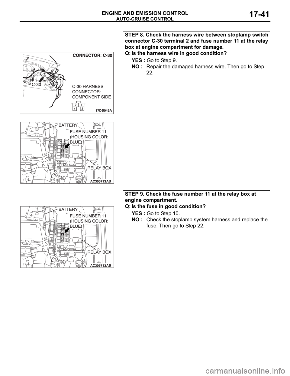
STEP 8. Check the harness wire between stoplamp switch
connector C-30 terminal 2 and fuse number 11 at the relay
box at engine compartment for damage.
Q: Is the harness wire in good condition?
YES : Go to Step 9.
NO : Repair the damaged harness wire. Then go to Step
22.
STEP 9. Check the fuse number 11 at the relay box at
engine compartment.
Q: Is the fuse in good condition?
YES : Go to Step 10.
NO : Check the stoplamp system harness and replace the
fuse. Then go to Step 22.
Page 1373 of 1500
AUTO-CRUISE CONTROL
ENGINE AND EMISSION CONTROL17-42
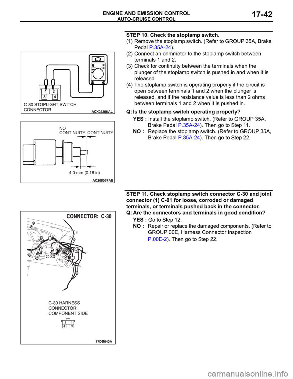
STEP 10. Check the stoplamp switch.
(1) Remove the stoplamp switch. (Refer to GROUP 35A, Brake
Pedal P.35A-24).
(2) Connect an ohmmeter to the stoplamp switch between
terminals 1 and 2.
(3) Check for continuity between the terminals when the
plunger of the stoplamp switch is pushed in and when it is
released.
(4) The stoplamp switch is operating properly if the circuit is
open between terminals 1 and 2 when the plunger is
released, and if the resistance value is less than 2 ohms
between terminals 1 and 2 when it is pushed in.
Q: Is the stoplamp switch operating properly?
YES : Install the stoplamp switch. (Refer to GROUP 35A,
Brake Pedal P.35A-24). Then go to Step 11.
NO : Replace the stoplamp switch. (Refer to GROUP 35A,
Brake Pedal P.35A-24). Then go to Step 22.
STEP 11. Check stoplamp switch connector C-30 and joint
connector (1) C-01 for loose, corroded or damaged
terminals, or terminals pushed back in the connector.
Q: Are the connectors and terminals in good condition?
YES : Go to Step 12.
NO : Repair or replace the damaged components. (Refer to
GROUP 00E, Harness Connector Inspection
P.00E-2). Then go to Step 22.
Page 1374 of 1500
AUTO-CRUISE CONTROL
ENGINE AND EMISSION CONTROL17-43
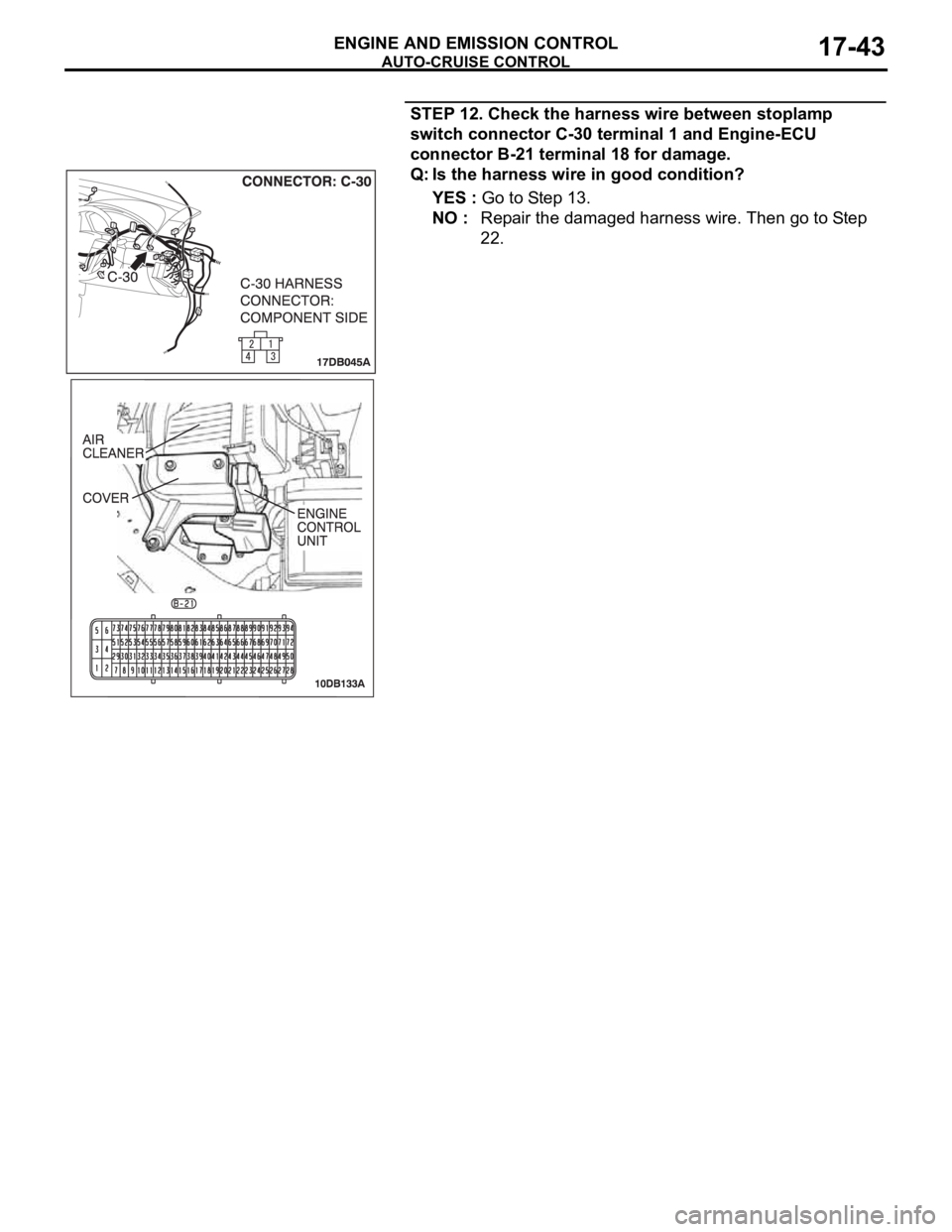
STEP 12. Check the harness wire between stoplamp
switch connector C-30 terminal 1 and Engine-ECU
connector B-21 terminal 18 for damage.
Q: Is the harness wire in good condition?
YES : Go to Step 13.
NO : Repair the damaged harness wire. Then go to Step
22.
Page 1375 of 1500
AUTO-CRUISE CONTROL
ENGINE AND EMISSION CONTROL17-44
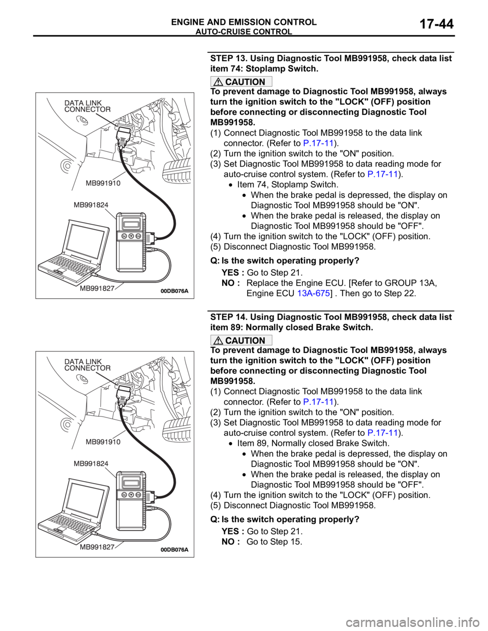
STEP 13. Using Diagnostic Tool MB991958, check data list
item 74: Stoplamp Switch.
To prevent damage to Diagnostic Tool MB991958, always
turn the ignition switch to the "LOCK" (OFF) position
before connecting or disconnecting Diagnostic Tool
MB991958.
(1) Connect Diagnostic Tool MB991958 to the data link
connector. (Refer to P.17-11).
(2) Turn the ignition switch to the "ON" position.
(3) Set Diagnostic Tool MB991958 to data reading mode for
auto-cruise control system. (Refer to P.17-11).
Item 74, Stoplamp Switch.
When the brake pedal is depressed, the display on
Diagnostic Tool MB991958 should be "ON".
When the brake pedal is released, the display on
Diagnostic Tool MB991958 should be "OFF".
(4) Turn the ignition switch to the "LOCK" (OFF) position.
(5) Disconnect Diagnostic Tool MB991958.
Q: Is the switch operating properly?
YES : Go to Step 21.
NO : Replace the Engine ECU. [Refer to GROUP 13A,
Engine ECU 13A-675] . Then go to Step 22.
STEP 14. Using Diagnostic Tool MB991958, check data list
item 89: Normally closed Brake Switch.
To prevent damage to Diagnostic Tool MB991958, always
turn the ignition switch to the "LOCK" (OFF) position
before connecting or disconnecting Diagnostic Tool
MB991958.
(1) Connect Diagnostic Tool MB991958 to the data link
connector. (Refer to P.17-11).
(2) Turn the ignition switch to the "ON" position.
(3) Set Diagnostic Tool MB991958 to data reading mode for
auto-cruise control system. (Refer to P.17-11).
Item 89, Normally closed Brake Switch.
When the brake pedal is depressed, the display on
Diagnostic Tool MB991958 should be "ON".
When the brake pedal is released, the display on
Diagnostic Tool MB991958 should be "OFF".
(4) Turn the ignition switch to the "LOCK" (OFF) position.
(5) Disconnect Diagnostic Tool MB991958.
Q: Is the switch operating properly?
YES : Go to Step 21.
NO : Go to Step 15.
Page 1376 of 1500
AUTO-CRUISE CONTROL
ENGINE AND EMISSION CONTROL17-45
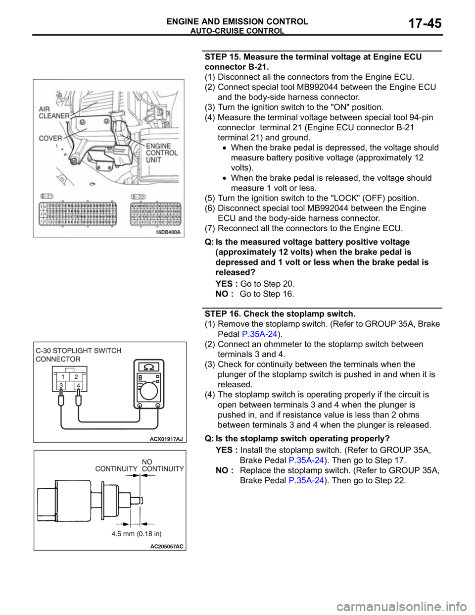
STEP 15. Measure the terminal voltage at Engine ECU
connector B-21.
(1) Disconnect all the connectors from the Engine ECU.
(2) Connect special tool MB992044 between the Engine ECU
and the body-side harness connector.
(3) Turn the ignition switch to the "ON" position.
(4) Measure the terminal voltage between special tool 94-pin
connector terminal 21 (Engine ECU connector B-21
terminal 21) and ground.
When the brake pedal is depressed, the voltage should
measure battery positive voltage (approximately 12
volts).
When the brake pedal is released, the voltage should
measure 1 volt or less.
(5) Turn the ignition switch to the "LOCK" (OFF) position.
(6) Disconnect special tool MB992044 between the Engine
ECU and the body-side harness connector.
(7) Reconnect all the connectors to the Engine ECU.
Q: Is the measured voltage battery positive voltage
(approximately 12 volts) when the brake pedal is
depressed and 1 volt or less when the brake pedal is
released?
YES : Go to Step 20.
NO : Go to Step 16.
STEP 16. Check the stoplamp switch.
(1) Remove the stoplamp switch. (Refer to GROUP 35A, Brake
Pedal P.35A-24).
(2) Connect an ohmmeter to the stoplamp switch between
terminals 3 and 4.
(3) Check for continuity between the terminals when the
plunger of the stoplamp switch is pushed in and when it is
released.
(4) The stoplamp switch is operating properly if the circuit is
open between terminals 3 and 4 when the plunger is
pushed in, and if resistance value is less than 2 ohms
between terminals 3 and 4 when the plunger is released.
Q: Is the stoplamp switch operating properly?
YES : Install the stoplamp switch. (Refer to GROUP 35A,
Brake Pedal P.35A-24). Then go to Step 17.
NO : Replace the stoplamp switch. (Refer to GROUP 35A,
Brake Pedal P.35A-24). Then go to Step 22.