engine MITSUBISHI 380 2005 Workshop Manual
[x] Cancel search | Manufacturer: MITSUBISHI, Model Year: 2005, Model line: 380, Model: MITSUBISHI 380 2005Pages: 1500, PDF Size: 47.87 MB
Page 1347 of 1500
AUTO-CRUISE CONTROL
ENGINE AND EMISSION CONTROL17-16
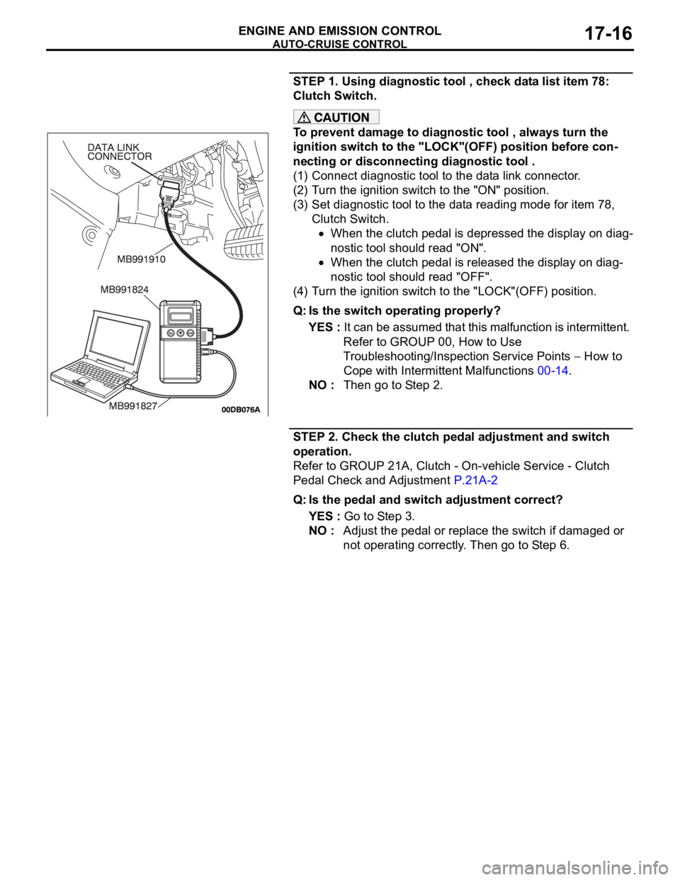
STEP 1. Using diagnostic tool , check data list item 78:
Clutch Switch.
To prevent damage to diagnostic tool , always turn the
ignition switch to the "LOCK"(OFF) position before con-
necting or disconnecting diagnostic tool .
(1) Connect diagnostic tool to the data link connector.
(2) Turn the ignition switch to the "ON" position.
(3) Set diagnostic tool to the data reading mode for item 78,
Clutch Switch.
When the clutch pedal is depressed the display on diag-
nostic tool should read "ON".
When the clutch pedal is released the display on diag-
nostic tool should read "OFF".
(4) Turn the ignition switch to the "LOCK"(OFF) position.
Q: Is the switch operating properly?
YES : It can be assumed that this malfunction is intermittent.
Refer to GROUP 00, How to Use
Troubleshooting/Inspection Service Points
How to
Cope with Intermittent Malfunctions 00-14.
NO : Then go to Step 2.
STEP 2. Check the clutch pedal adjustment and switch
operation.
Refer to GROUP 21A, Clutch - On-vehicle Service - Clutch
Pedal Check and Adjustment P.21A-2
Q: Is the pedal and switch adjustment correct?
YES : Go to Step 3.
NO : Adjust the pedal or replace the switch if damaged or
not operating correctly. Then go to Step 6.
Page 1348 of 1500
AUTO-CRUISE CONTROL
ENGINE AND EMISSION CONTROL17-17
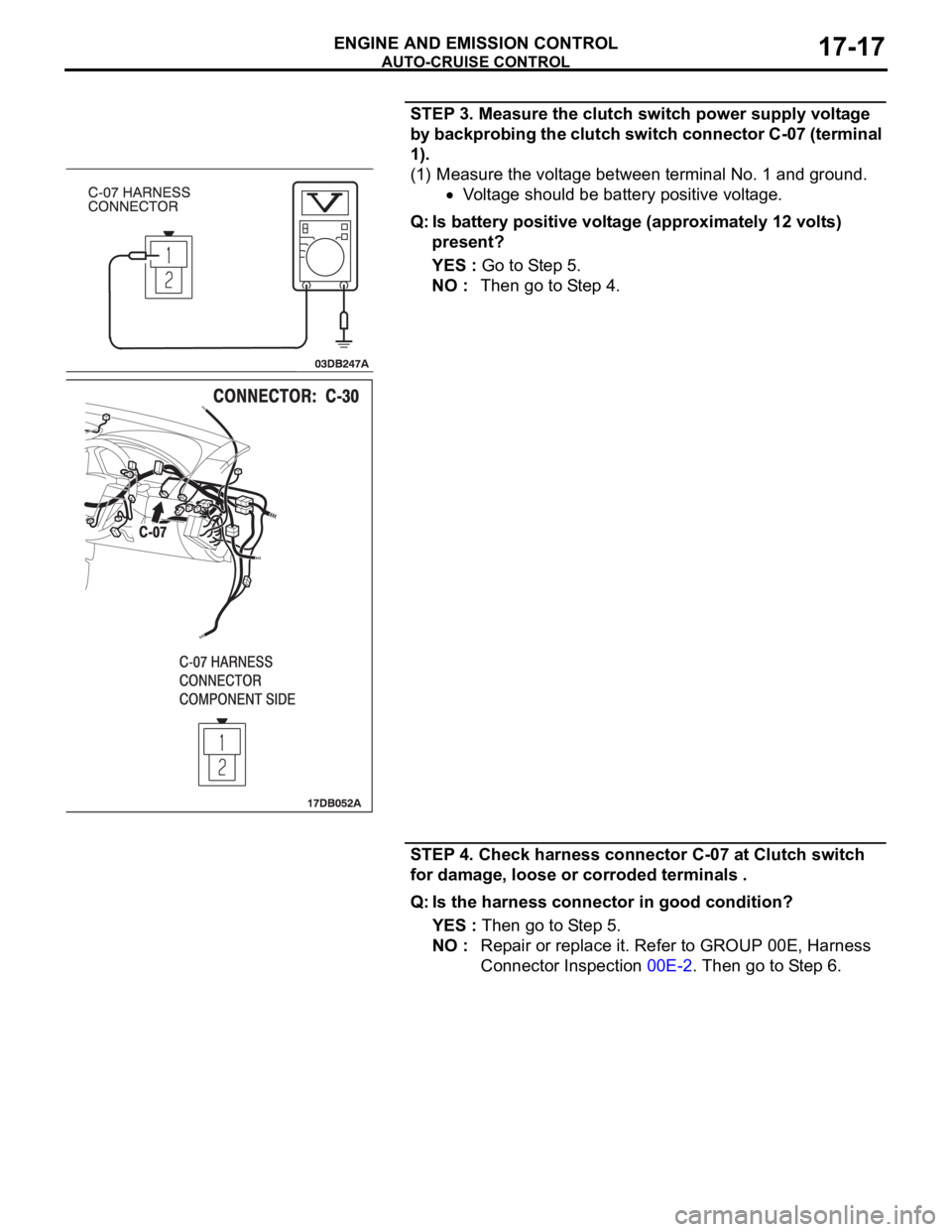
STEP 3. Measure the clutch switch power supply voltage
by backprobing the clutch switch connector C-07 (terminal
1).
(1) Measure the voltage between terminal No. 1 and ground.
Voltage should be battery positive voltage.
Q: Is battery positive voltage (approximately 12 volts)
present?
YES : Go to Step 5.
NO : Then go to Step 4.
STEP 4. Check harness connector C-07 at Clutch switch
for damage, loose or corroded terminals .
Q: Is the harness connector in good condition?
YES : Then go to Step 5.
NO : Repair or replace it. Refer to GROUP 00E, Harness
Connector Inspection 00E-2. Then go to Step 6.
Page 1349 of 1500
AUTO-CRUISE CONTROL
ENGINE AND EMISSION CONTROL17-18
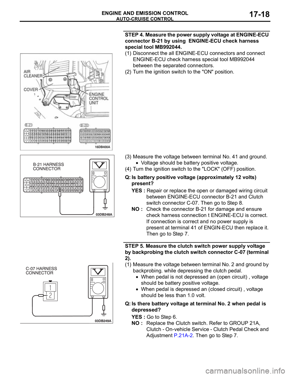
STEP 4. Measure the power supply voltage at ENGINE-ECU
connector B-21 by using ENGINE-ECU check harness
special tool MB992044.
(1) Disconnect the all ENGINE-ECU connectors and connect
ENGINE-ECU check harness special tool MB992044
between the separated connectors.
(2) Turn the ignition switch to the "ON" position.
(3) Measure the voltage between terminal No. 41 and ground.
Voltage should be battery positive voltage.
(4) Turn the ignition switch to the "LOCK" (OFF) position.
Q: Is battery positive voltage (approximately 12 volts)
present?
YES : Repair or replace the open or damaged wiring circuit
between ENGINE-ECU connector B-21 and Clutch
switch connector C-07. Then go to Step 8.
NO : Check the connector B-21 for damage and ensure
check harness connection t ENGINE-ECU is correct.
If connection is correct and no power supply is
present at terminal 41 of ENGIN-ECU then replace it.
Then go to Step 7.
STEP 5. Measure the clutch switch power supply voltage
by backprobing the clutch switch connector C-07 (terminal
2).
(1) Measure the voltage between terminal No. 2 and ground by
backprobing. while depressing the clutch pedal.
When pedal is not depressed an (open circuit) , voltage
should be battery positive voltage.
When pedal is depressed an (closed circuit) , voltage
should be less than 1.0 volt.
Q: Is there battery voltage at terminal No. 2 when pedal is
depressed?
YES : Go to Step 6.
NO : Replace the Clutch switch. Refer to GROUP 21A,
Clutch - On-vehicle Service - Clutch Pedal Check and
Adjustment P.21A-2. Then go to Step 7.
Page 1350 of 1500
AUTO-CRUISE CONTROL
ENGINE AND EMISSION CONTROL17-19
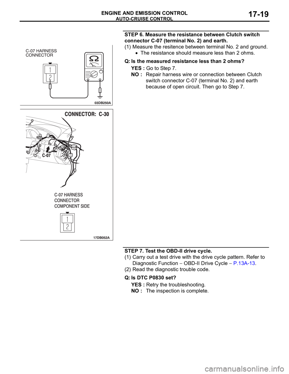
STEP 6. Measure the resistance between Clutch switch
connector C-07 (terminal No. 2) and earth.
(1) Measure the resitence between terminal No. 2 and ground.
The resistance should measure less than 2 ohms.
Q: Is the measured resistance less than 2 ohms?
YES : Go to Step 7.
NO : Repair harness wire or connection between Clutch
switch connector C-07 (terminal No. 2) and earth
because of open circuit. Then go to Step 7.
STEP 7. Test the OBD-II drive cycle.
(1) Carry out a test drive with the drive cycle pattern. Refer to
Diagnostic Function
OBD-II Drive Cycle P.13A-13.
(2) Read the diagnostic trouble code.
Q: Is DTC P0830 set?
YES : Retry the troubleshooting.
NO : The inspection is complete.
Page 1351 of 1500
AUTO-CRUISE CONTROL
ENGINE AND EMISSION CONTROL17-20
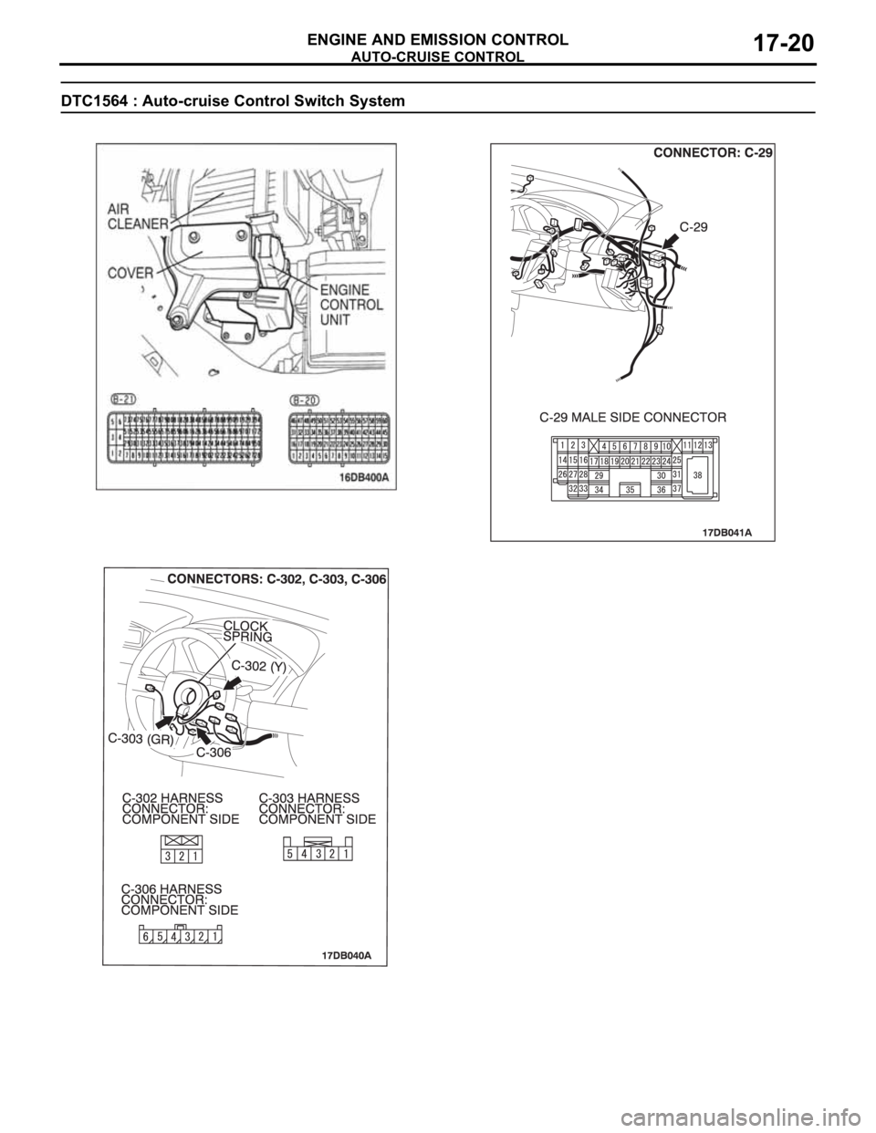
DTC1564 : Auto-cruise Control Switch System
.
Page 1352 of 1500

AUTO-CRUISE CONTROL
ENGINE AND EMISSION CONTROL17-21
CIRCUIT OPERATION
This circuit judges the signals of each switch
("COAST/SET", "ACC/RES" and "CANCEL") of the
auto-cruise control switch. The Engine ECU detects
the state of the auto-cruise control switch by sensing
the voltages shown below.
When all switches are OFF: 4.7 5.0 volts
When the "CRUISE" (MAIN) switch is "ON": 0
0.3 volt
When the "COAST/SET" switch is ON: 2.0 2.8
volts
When the "ACC/RES" switch is ON: 3.3 4.1
volts
When the "CANCEL" switch is ON: 0.8 1.5 volts
.
DTC SET CONDITIONS
Check Condition
The "CRUISE" indicator lamp illuminates.Judgement Criteria
If the auto-cruise control switch is operated, this
DTC will be set when the Engine ECU terminal
voltage is different from the standard value.
.
TROUBLESHOOTING HINTS (THE MOST
LIKELY CAUSES FOR THIS CASE:)
Malfunction of the auto-cruise control switch.
Malfunction of the clock spring.
Damaged harness or connector.
Malfunction of the Engine ECU.
Circuit drawings
Refer to circuit diagrams GROUP-90
Refer to configuration diagrams GROUP-80
Refer to component locations GROUP-70
DIAGNOSIS
Required Special Tools:
MB991958: Diagnostic Tool (MUT-III Sub Assembly)
MB991824: V.C.I.
MB991827: MUT-III USB Cable
MB991910: MUT-III Main Harness A
MB991223: Harness Set
MB992044: ENGINE-ECU Check Harness
Page 1353 of 1500
AUTO-CRUISE CONTROL
ENGINE AND EMISSION CONTROL17-22
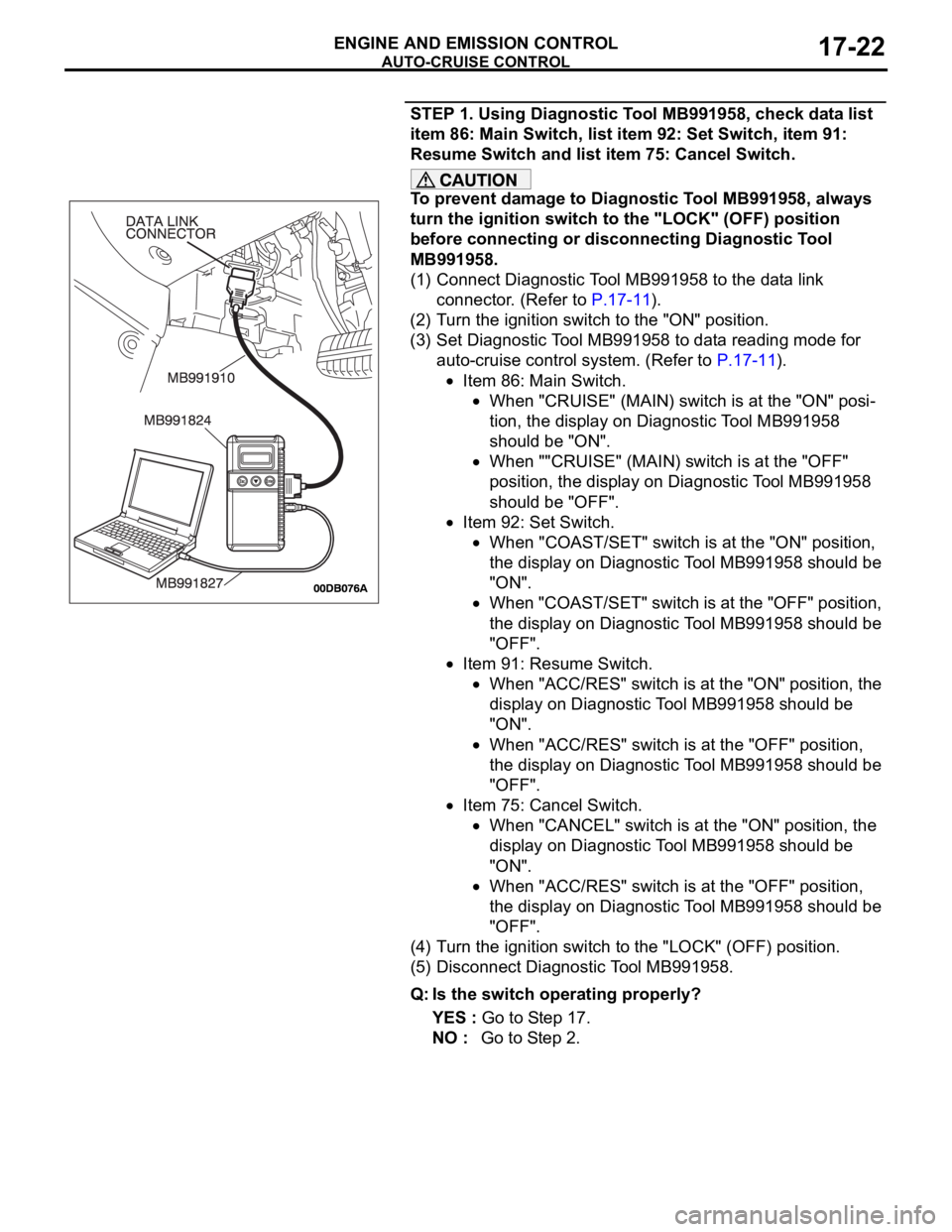
STEP 1. Using Diagnostic Tool MB991958, check data list
item 86: Main Switch, list item 92: Set Switch, item 91:
Resume Switch and list item 75: Cancel Switch.
To prevent damage to Diagnostic Tool MB991958, always
turn the ignition switch to the "LOCK" (OFF) position
before connecting or disconnecting Diagnostic Tool
MB991958.
(1) Connect Diagnostic Tool MB991958 to the data link
connector. (Refer to P.17-11).
(2) Turn the ignition switch to the "ON" position.
(3) Set Diagnostic Tool MB991958 to data reading mode for
auto-cruise control system. (Refer to P.17-11).
Item 86: Main Switch.
When "CRUISE" (MAIN) switch is at the "ON" posi-
tion, the display on Diagnostic Tool MB991958
should be "ON".
When ""CRUISE" (MAIN) switch is at the "OFF"
position, the display on Diagnostic Tool MB991958
should be "OFF".
Item 92: Set Switch.
When "COAST/SET" switch is at the "ON" position,
the display on Diagnostic Tool MB991958 should be
"ON".
When "COAST/SET" switch is at the "OFF" position,
the display on Diagnostic Tool MB991958 should be
"OFF".
Item 91: Resume Switch.
When "ACC/RES" switch is at the "ON" position, the
display on Diagnostic Tool MB991958 should be
"ON".
When "ACC/RES" switch is at the "OFF" position,
the display on Diagnostic Tool MB991958 should be
"OFF".
Item 75: Cancel Switch.
When "CANCEL" switch is at the "ON" position, the
display on Diagnostic Tool MB991958 should be
"ON".
When "ACC/RES" switch is at the "OFF" position,
the display on Diagnostic Tool MB991958 should be
"OFF".
(4) Turn the ignition switch to the "LOCK" (OFF) position.
(5) Disconnect Diagnostic Tool MB991958.
Q: Is the switch operating properly?
YES : Go to Step 17.
NO : Go to Step 2.
Page 1354 of 1500
AUTO-CRUISE CONTROL
ENGINE AND EMISSION CONTROL17-23
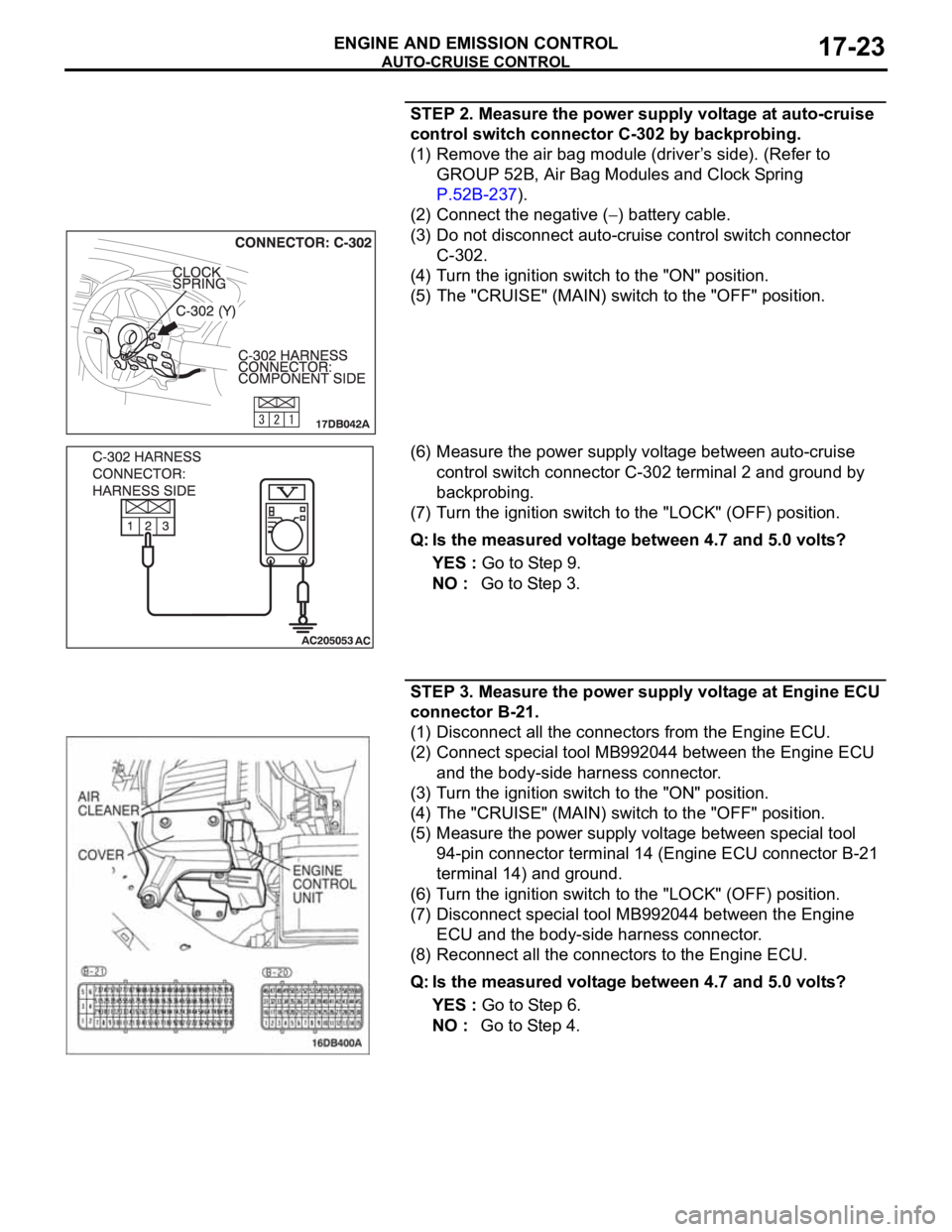
STEP 2. Measure the power supply voltage at auto-cruise
control switch connector C-302 by backprobing.
(1) Remove the air bag module (driver’s side). (Refer to
GROUP 52B, Air Bag Modules and Clock Spring
P.52B-237).
(2) Connect the negative (
) battery cable.
(3) Do not disconnect auto-cruise control switch connector
C-302.
(4) Turn the ignition switch to the "ON" position.
(5) The "CRUISE" (MAIN) switch to the "OFF" position.
(6) Measure the power supply voltage between auto-cruise
control switch connector C-302 terminal 2 and ground by
backprobing.
(7) Turn the ignition switch to the "LOCK" (OFF) position.
Q: Is the measured voltage between 4.7 and 5.0 volts?
YES : Go to Step 9.
NO : Go to Step 3.
STEP 3. Measure the power supply voltage at Engine ECU
connector B-21.
(1) Disconnect all the connectors from the Engine ECU.
(2) Connect special tool MB992044 between the Engine ECU
and the body-side harness connector.
(3) Turn the ignition switch to the "ON" position.
(4) The "CRUISE" (MAIN) switch to the "OFF" position.
(5) Measure the power supply voltage between special tool
94-pin connector terminal 14 (Engine ECU connector B-21
terminal 14) and ground.
(6) Turn the ignition switch to the "LOCK" (OFF) position.
(7) Disconnect special tool MB992044 between the Engine
ECU and the body-side harness connector.
(8) Reconnect all the connectors to the Engine ECU.
Q: Is the measured voltage between 4.7 and 5.0 volts?
YES : Go to Step 6.
NO : Go to Step 4.
Page 1355 of 1500

AUTO-CRUISE CONTROL
ENGINE AND EMISSION CONTROL17-24
STEP 4. Check Engine ECU connector B-21 for loose,
corroded or damaged terminals, or terminals pushed back
in the connector.
Q: Are the connector and terminals in good condition?
YES : Go to Step 5.
NO : Repair the faulty connector if possible or as
recommended, replace complete wiring harness.
(Refer to GROUP 00E, Harness Connector Inspection
P.00E-2). Install the air bag module (driver’s side).
(Refer to GROUP 52B, Air Bag Modules and Clock
Spring P.52B-237). Then go to Step 18.
STEP 5. Check the harness for short circuit to ground
between the Engine ECU connector B-21 terminal 14 and
the auto-cruise control switch connector C-302 terminal 2.
(1) Disconnect Engine ECU connector B-21 and measure at
the harness connector side.
(2) Turn the ignition switch to the "LOCK" (OFF) position.
(3) Measure the continuity between Engine ECU connector
B-21 terminal 14 and ground.
(4) Reconnect Engine ECU connector B-21.
Q: Is the measured continuity open circuit?
YES : Install the air bag module (driver’s side). (Refer to
GROUP 52B, Air Bag Modules and Clock Spring
P.52B-237). Then go to Step 17.
NO : Go to Step 6.
Page 1356 of 1500
AUTO-CRUISE CONTROL
ENGINE AND EMISSION CONTROL17-25
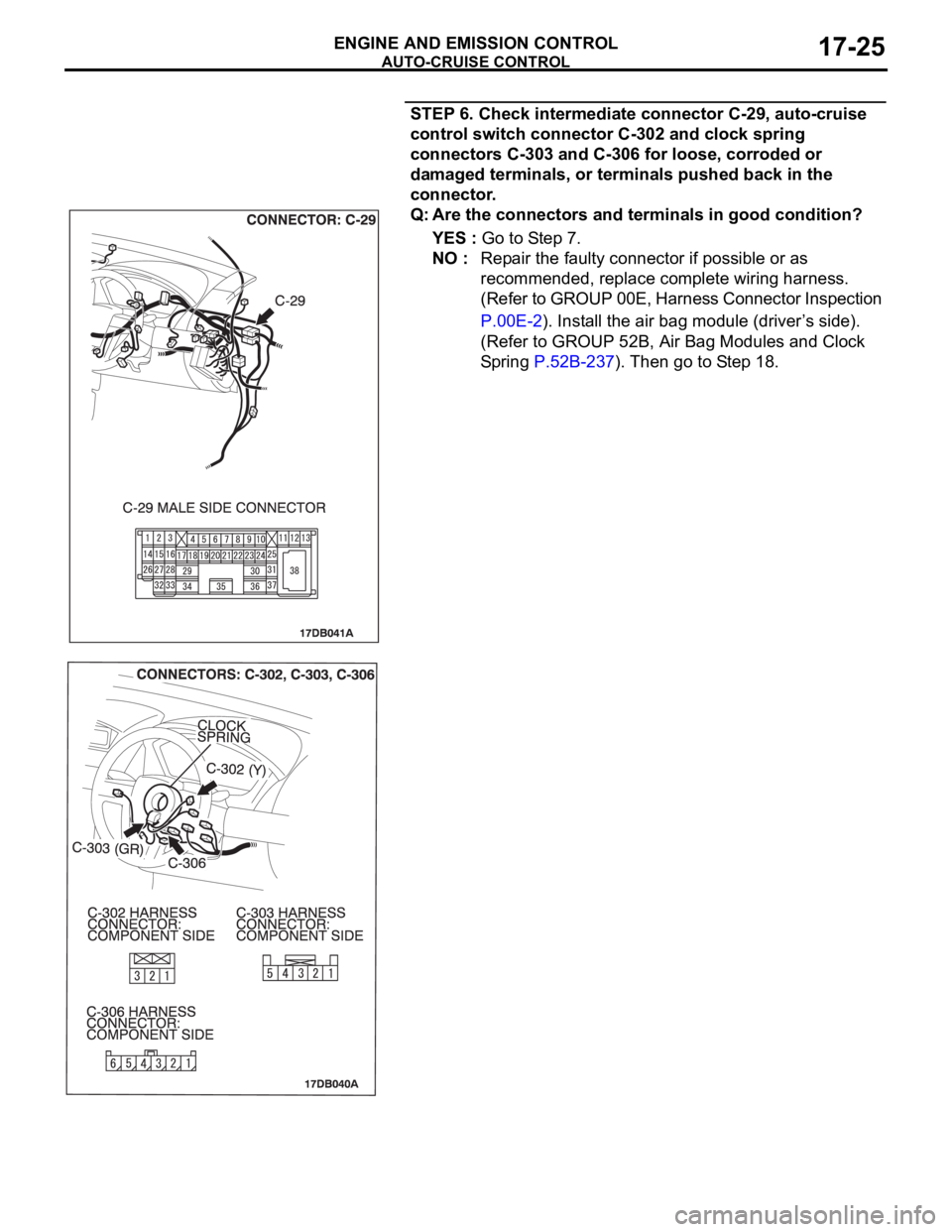
STEP 6. Check intermediate connector C-29, auto-cruise
control switch connector C-302 and clock spring
connectors C-303 and C-306 for loose, corroded or
damaged terminals, or terminals pushed back in the
connector.
Q: Are the connectors and terminals in good condition?
YES : Go to Step 7.
NO : Repair the faulty connector if possible or as
recommended, replace complete wiring harness.
(Refer to GROUP 00E, Harness Connector Inspection
P.00E-2). Install the air bag module (driver’s side).
(Refer to GROUP 52B, Air Bag Modules and Clock
Spring P.52B-237). Then go to Step 18.