Ignition MITSUBISHI 380 2005 Workshop Manual
[x] Cancel search | Manufacturer: MITSUBISHI, Model Year: 2005, Model line: 380, Model: MITSUBISHI 380 2005Pages: 1500, PDF Size: 47.87 MB
Page 756 of 1500
AUTO A/C DIAGNOSIS
HEATER, AIR CONDITIONING AND VENTILATION55-55
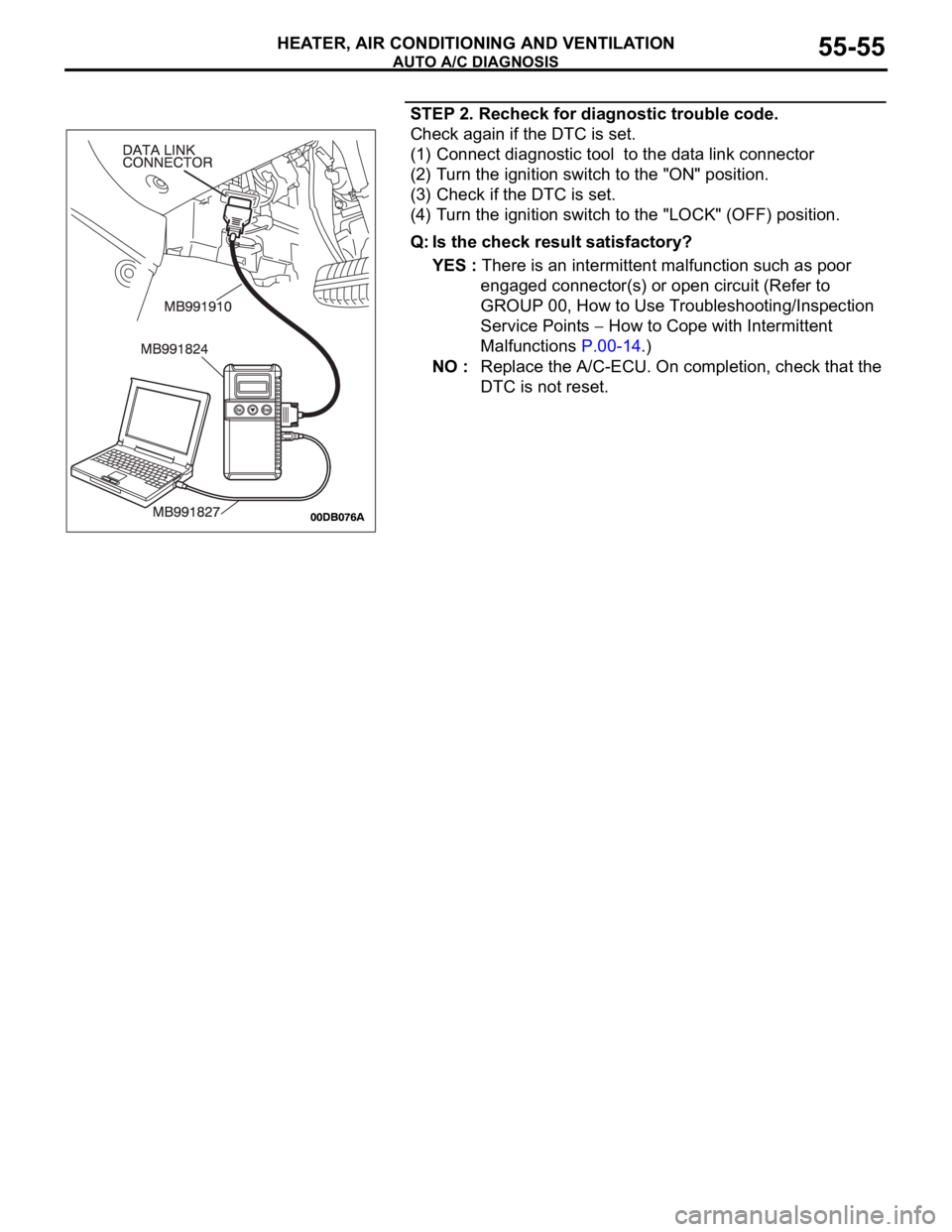
STEP 2. Recheck for diagnostic trouble code.
Check again if the DTC is set.
(1) Connect diagnostic tool to the data link connector
(2) Turn the ignition switch to the "ON" position.
(3) Check if the DTC is set.
(4) Turn the ignition switch to the "LOCK" (OFF) position.
Q: Is the check result satisfactory?
YES : There is an intermittent malfunction such as poor
engaged connector(s) or open circuit (Refer to
GROUP 00, How to Use Troubleshooting/Inspection
Service Points
How to Cope with Intermittent
Malfunctions P.00-14.)
NO : Replace the A/C-ECU. On completion, check that the
DTC is not reset.
Page 758 of 1500
AUTO A/C DIAGNOSIS
HEATER, AIR CONDITIONING AND VENTILATION55-57
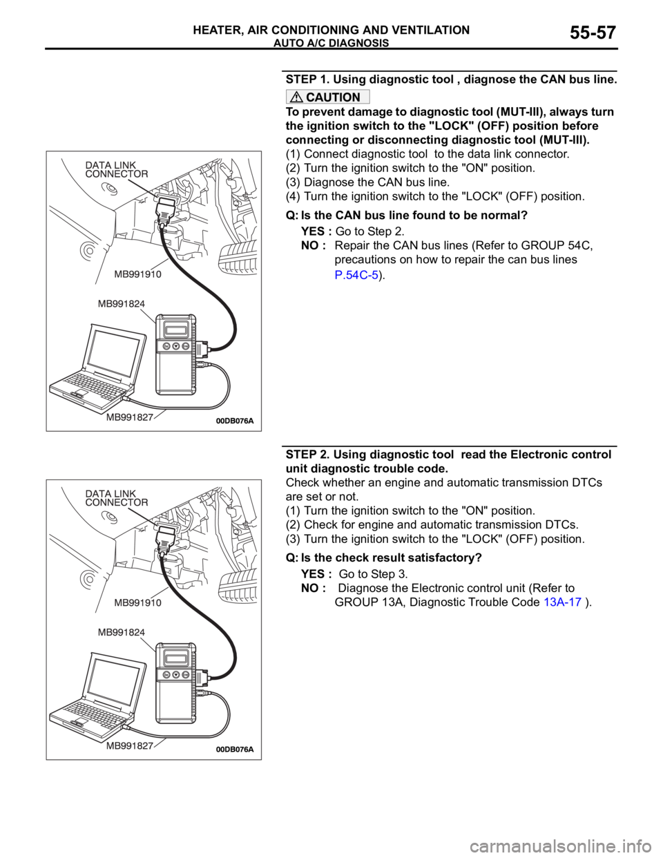
STEP 1. Using diagnostic tool , diagnose the CAN bus line.
To prevent damage to diagnostic tool (MUT-III), always turn
the ignition switch to the "LOCK" (OFF) position before
connecting or disconnecting diagnostic tool (MUT-III).
(1) Connect diagnostic tool to the data link connector.
(2) Turn the ignition switch to the "ON" position.
(3) Diagnose the CAN bus line.
(4) Turn the ignition switch to the "LOCK" (OFF) position.
Q: Is the CAN bus line found to be normal?
YES : Go to Step 2.
NO : Repair the CAN bus lines (Refer to GROUP 54C,
precautions on how to repair the can bus lines
P.54C-5).
STEP 2. Using diagnostic tool read the Electronic control
unit diagnostic trouble code.
Check whether an engine and automatic transmission DTCs
are set or not.
(1) Turn the ignition switch to the "ON" position.
(2) Check for engine and automatic transmission DTCs.
(3) Turn the ignition switch to the "LOCK" (OFF) position.
Q: Is the check result satisfactory?
YES : Go to Step 3.
NO : Diagnose the Electronic control unit (Refer to
GROUP 13A, Diagnostic Trouble Code 13A-17 ).
Page 759 of 1500
AUTO A/C DIAGNOSIS
HEATER, AIR CONDITIONING AND VENTILATION55-58
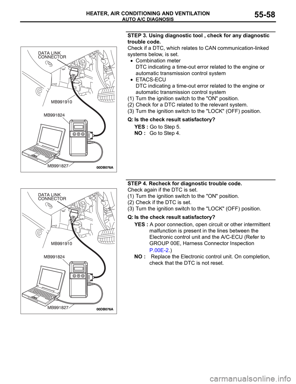
STEP 3. Using diagnostic tool , check for any diagnostic
trouble code.
Check if a DTC, which relates to CAN communication-linked
systems below, is set.
Combination meter
DTC indicating a time-out error related to the engine or
automatic transmission control system
ETACS-ECU
DTC indicating a time-out error related to the engine or
automatic transmission control system
(1) Turn the ignition switch to the "ON" position.
(2) Check for a DTC related to the relevant system.
(3) Turn the ignition switch to the "LOCK" (OFF) position.
Q: Is the check result satisfactory?
YES : Go to Step 5.
NO : Go to Step 4.
STEP 4. Recheck for diagnostic trouble code.
Check again if the DTC is set.
(1) Turn the ignition switch to the "ON" position.
(2) Check if the DTC is set.
(3) Turn the ignition switch to the "LOCK" (OFF) position.
Q: Is the check result satisfactory?
YES : A poor connection, open circuit or other intermittent
malfunction is present in the lines between the
Electronic control unit and the A/C-ECU (Refer to
GROUP 00E, Harness Connector Inspection
P.00E-2.)
NO : Replace the Electronic control unit. On completion,
check that the DTC is not reset.
Page 760 of 1500
AUTO A/C DIAGNOSIS
HEATER, AIR CONDITIONING AND VENTILATION55-59
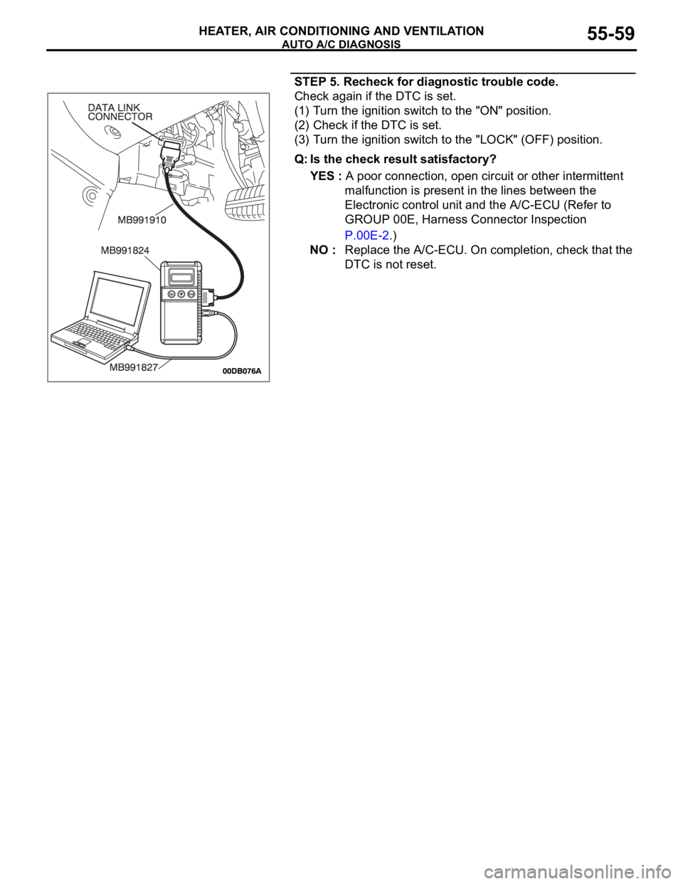
STEP 5. Recheck for diagnostic trouble code.
Check again if the DTC is set.
(1) Turn the ignition switch to the "ON" position.
(2) Check if the DTC is set.
(3) Turn the ignition switch to the "LOCK" (OFF) position.
Q: Is the check result satisfactory?
YES : A poor connection, open circuit or other intermittent
malfunction is present in the lines between the
Electronic control unit and the A/C-ECU (Refer to
GROUP 00E, Harness Connector Inspection
P.00E-2.)
NO : Replace the A/C-ECU. On completion, check that the
DTC is not reset.
Page 762 of 1500

AUTO A/C DIAGNOSIS
HEATER, AIR CONDITIONING AND VENTILATION55-61
STEP 1. Using diagnostic tool , diagnose the CAN bus line.
To prevent damage to diagnostic tool (MUT-III), always turn
the ignition switch to the "LOCK" (OFF) position before
connecting or disconnecting diagnostic tool (MUT-III).
(1) Connect diagnostic tool to the data link connector.
(2) Turn the ignition switch to the "ON" position.
(3) Diagnose the CAN bus line.
(4) Turn the ignition switch to the "LOCK" (OFF) position.
Q: Is the CAN bus line found to be normal?
YES : Go to Step 2.
NO : Repair the CAN bus line (Refer to GROUP 54C,
Diagnosis P.54C-15).
STEP 2. Using diagnostic tool , read the Electronic control
unit diagnostic trouble code.
Check that the multi-center display unit sets a DTC.
(1) Turn the ignition switch to the "ON" position.
(2) Check for the DTC related to the multi-center display unit.
(3) Turn the ignition switch to the "LOCK" (OFF) position.
Q: Is the check result satisfactory?
YES : Refer to GROUP 54A, multi-center display unit
Diagnosis P.54A-254.
NO : Go to Step 3.
Page 763 of 1500
AUTO A/C DIAGNOSIS
HEATER, AIR CONDITIONING AND VENTILATION55-62
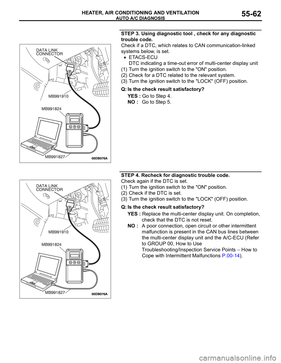
STEP 3. Using diagnostic tool , check for any diagnostic
trouble code.
Check if a DTC, which relates to CAN communication-linked
systems below, is set.
ETACS-ECU
DTC indicating a time-out error of multi-center display unit
(1) Turn the ignition switch to the "ON" position.
(2) Check for a DTC related to the relevant system.
(3) Turn the ignition switch to the "LOCK" (OFF) position.
Q: Is the check result satisfactory?
YES : Go to Step 4.
NO : Go to Step 5.
STEP 4. Recheck for diagnostic trouble code.
Check again if the DTC is set.
(1) Turn the ignition switch to the "ON" position.
(2) Check if the DTC is set.
(3) Turn the ignition switch to the "LOCK" (OFF) position.
Q: Is the check result satisfactory?
YES : Replace the multi-center display unit. On completion,
check that the DTC is not reset.
NO : A poor connection, open circuit or other intermittent
malfunction is present in the CAN bus lines between
the multi-center display unit and the A/C-ECU (Refer
to GROUP 00, How to Use
Troubleshooting/Inspection Service Points
How to
Cope with Intermittent Malfunctions P.00-14).
Page 764 of 1500
AUTO A/C DIAGNOSIS
HEATER, AIR CONDITIONING AND VENTILATION55-63
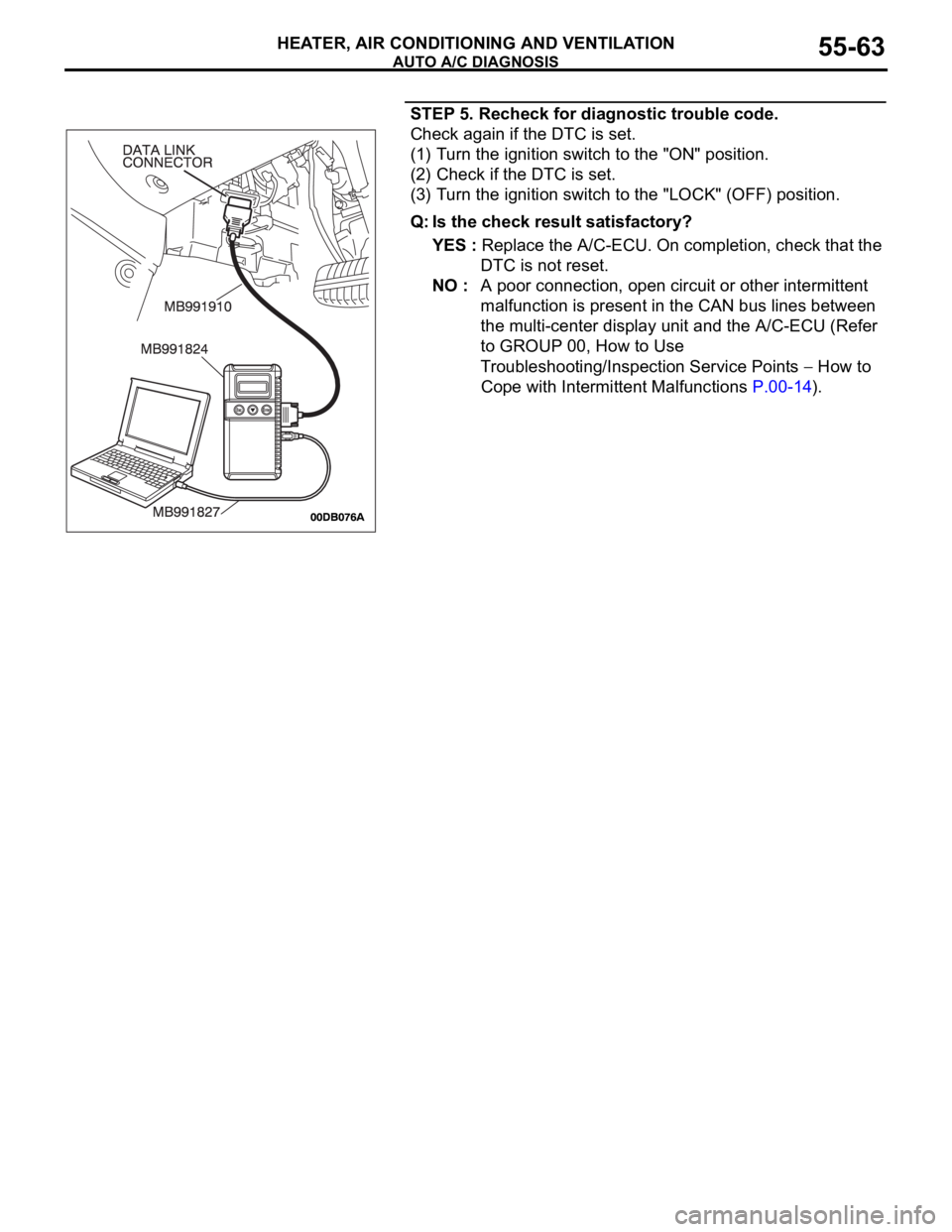
STEP 5. Recheck for diagnostic trouble code.
Check again if the DTC is set.
(1) Turn the ignition switch to the "ON" position.
(2) Check if the DTC is set.
(3) Turn the ignition switch to the "LOCK" (OFF) position.
Q: Is the check result satisfactory?
YES : Replace the A/C-ECU. On completion, check that the
DTC is not reset.
NO : A poor connection, open circuit or other intermittent
malfunction is present in the CAN bus lines between
the multi-center display unit and the A/C-ECU (Refer
to GROUP 00, How to Use
Troubleshooting/Inspection Service Points
How to
Cope with Intermittent Malfunctions P.00-14).
Page 766 of 1500
AUTO A/C DIAGNOSIS
HEATER, AIR CONDITIONING AND VENTILATION55-65
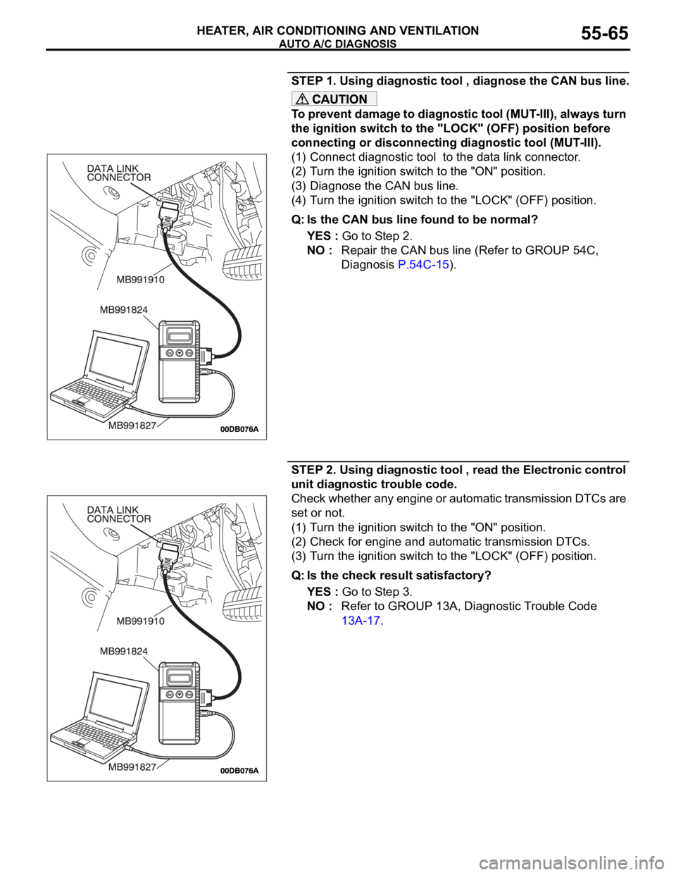
STEP 1. Using diagnostic tool , diagnose the CAN bus line.
To prevent damage to diagnostic tool (MUT-III), always turn
the ignition switch to the "LOCK" (OFF) position before
connecting or disconnecting diagnostic tool (MUT-III).
(1) Connect diagnostic tool to the data link connector.
(2) Turn the ignition switch to the "ON" position.
(3) Diagnose the CAN bus line.
(4) Turn the ignition switch to the "LOCK" (OFF) position.
Q: Is the CAN bus line found to be normal?
YES : Go to Step 2.
NO : Repair the CAN bus line (Refer to GROUP 54C,
Diagnosis P.54C-15).
STEP 2. Using diagnostic tool , read the Electronic control
unit diagnostic trouble code.
Check whether any engine or automatic transmission DTCs are
set or not.
(1) Turn the ignition switch to the "ON" position.
(2) Check for engine and automatic transmission DTCs.
(3) Turn the ignition switch to the "LOCK" (OFF) position.
Q: Is the check result satisfactory?
YES : Go to Step 3.
NO : Refer to GROUP 13A, Diagnostic Trouble Code
13A-17.
Page 767 of 1500
AUTO A/C DIAGNOSIS
HEATER, AIR CONDITIONING AND VENTILATION55-66
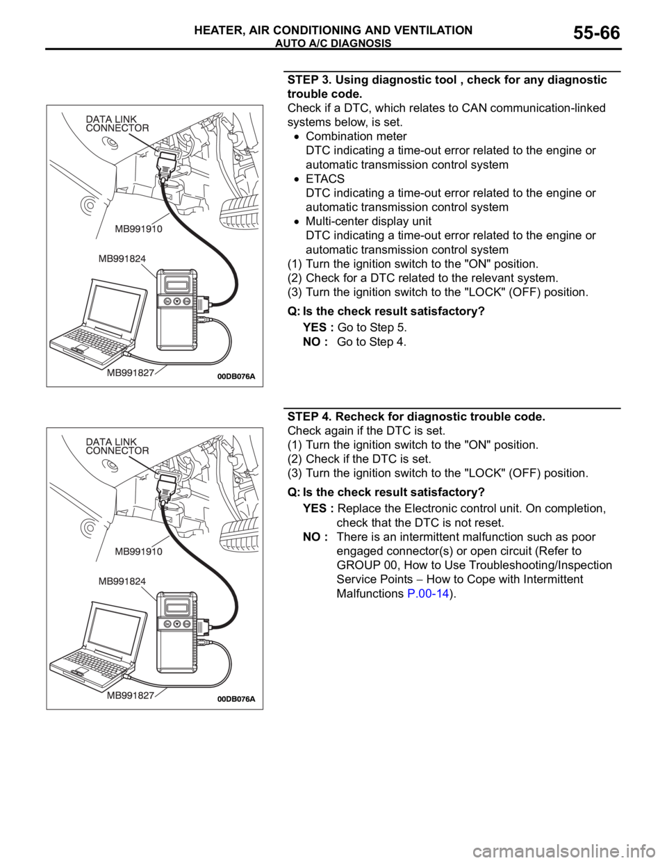
STEP 3. Using diagnostic tool , check for any diagnostic
trouble code.
Check if a DTC, which relates to CAN communication-linked
systems below, is set.
Combination meter
DTC indicating a time-out error related to the engine or
automatic transmission control system
ETACS
DTC indicating a time-out error related to the engine or
automatic transmission control system
Multi-center display unit
DTC indicating a time-out error related to the engine or
automatic transmission control system
(1) Turn the ignition switch to the "ON" position.
(2) Check for a DTC related to the relevant system.
(3) Turn the ignition switch to the "LOCK" (OFF) position.
Q: Is the check result satisfactory?
YES : Go to Step 5.
NO : Go to Step 4.
STEP 4. Recheck for diagnostic trouble code.
Check again if the DTC is set.
(1) Turn the ignition switch to the "ON" position.
(2) Check if the DTC is set.
(3) Turn the ignition switch to the "LOCK" (OFF) position.
Q: Is the check result satisfactory?
YES : Replace the Electronic control unit. On completion,
check that the DTC is not reset.
NO : There is an intermittent malfunction such as poor
engaged connector(s) or open circuit (Refer to
GROUP 00, How to Use Troubleshooting/Inspection
Service Points
How to Cope with Intermittent
Malfunctions P.00-14).
Page 768 of 1500
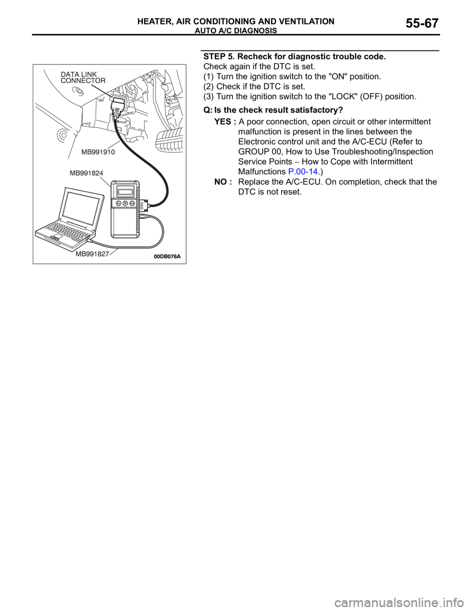
AUTO A/C DIAGNOSIS
HEATER, AIR CONDITIONING AND VENTILATION55-67
STEP 5. Recheck for diagnostic trouble code.
Check again if the DTC is set.
(1) Turn the ignition switch to the "ON" position.
(2) Check if the DTC is set.
(3) Turn the ignition switch to the "LOCK" (OFF) position.
Q: Is the check result satisfactory?
YES : A poor connection, open circuit or other intermittent
malfunction is present in the lines between the
Electronic control unit and the A/C-ECU (Refer to
GROUP 00, How to Use Troubleshooting/Inspection
Service Points
How to Cope with Intermittent
Malfunctions P.00-14.)
NO : Replace the A/C-ECU. On completion, check that the
DTC is not reset.