Ignition MITSUBISHI 380 2005 Workshop Manual
[x] Cancel search | Manufacturer: MITSUBISHI, Model Year: 2005, Model line: 380, Model: MITSUBISHI 380 2005Pages: 1500, PDF Size: 47.87 MB
Page 922 of 1500
ENGINE COOLING DIAGNOSIS
ENGINE COOLING14-7
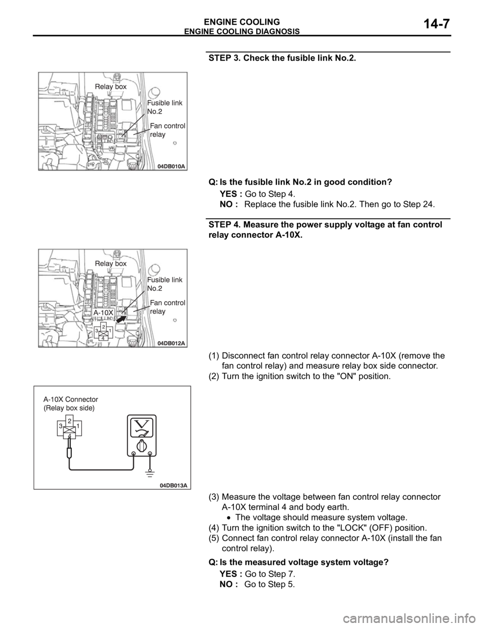
STEP 3. Check the fusible link No.2.
Q: Is the fusible link No.2 in good condition?
YES : Go to Step 4.
NO : Replace the fusible link No.2. Then go to Step 24.
STEP 4. Measure the power supply voltage at fan control
relay connector A-10X.
(1) Disconnect fan control relay connector A-10X (remove the
fan control relay) and measure relay box side connector.
(2) Turn the ignition switch to the "ON" position.
(3) Measure the voltage between fan control relay connector
A-10X terminal 4 and body earth.
The voltage should measure system voltage.
(4) Turn the ignition switch to the "LOCK" (OFF) position.
(5) Connect fan control relay connector A-10X (install the fan
control relay).
Q: Is the measured voltage system voltage?
YES : Go to Step 7.
NO : Go to Step 5.
Page 925 of 1500
ENGINE COOLING DIAGNOSIS
ENGINE COOLING14-10
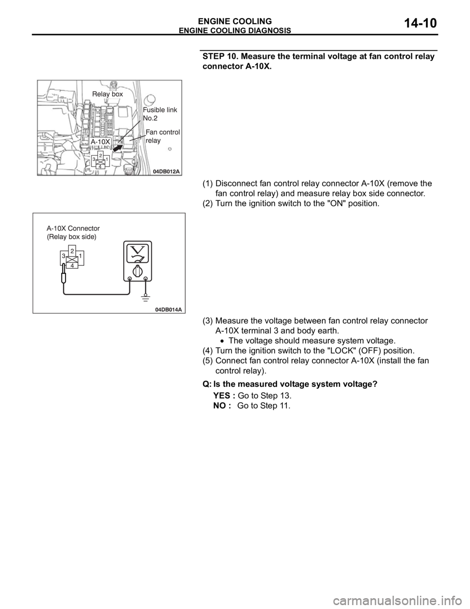
STEP 10. Measure the terminal voltage at fan control relay
connector A-10X.
(1) Disconnect fan control relay connector A-10X (remove the
fan control relay) and measure relay box side connector.
(2) Turn the ignition switch to the "ON" position.
(3) Measure the voltage between fan control relay connector
A-10X terminal 3 and body earth.
The voltage should measure system voltage.
(4) Turn the ignition switch to the "LOCK" (OFF) position.
(5) Connect fan control relay connector A-10X (install the fan
control relay).
Q: Is the measured voltage system voltage?
YES : Go to Step 13.
NO : Go to Step 11.
Page 934 of 1500
ENGINE COOLING DIAGNOSIS
ENGINE COOLING14-19
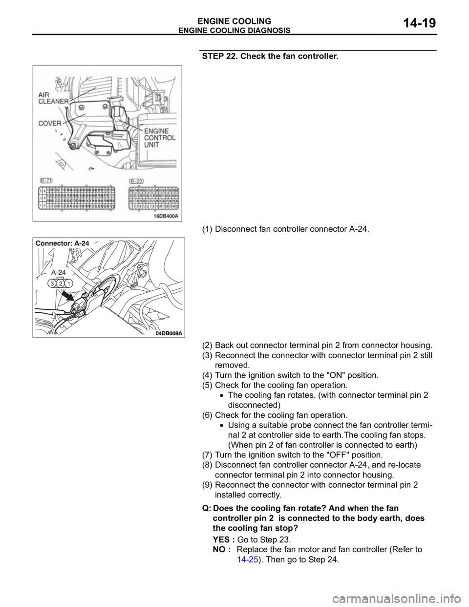
STEP 22. Check the fan controller.
(1) Disconnect fan controller connector A-24.
(2) Back out connector terminal pin 2 from connector housing.
(3) Reconnect the connector with connector terminal pin 2 still
removed.
(4) Turn the ignition switch to the "ON" position.
(5) Check for the cooling fan operation.
The cooling fan rotates. (with connector terminal pin 2
disconnected)
(6) Check for the cooling fan operation.
Using a suitable probe connect the fan controller termi-
nal 2 at controller side to earth.The cooling fan stops.
(When pin 2 of fan controller is connected to earth)
(7) Turn the ignition switch to the "OFF" position.
(8) Disconnect fan controller connector A-24, and re-locate
connector terminal pin 2 into connector housing.
(9) Reconnect the connector with connector terminal pin 2
installed correctly.
Q: Does the cooling fan rotate? And when the fan
controller pin 2 is connected to the body earth, does
the cooling fan stop?
YES : Go to Step 23.
NO : Replace the fan motor and fan controller (Refer to
14-25). Then go to Step 24.
Page 939 of 1500
ENGINE COOLING DIAGNOSIS
ENGINE COOLING14-24
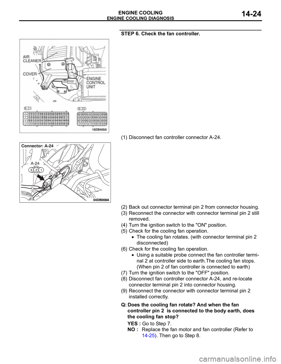
STEP 6. Check the fan controller.
(1) Disconnect fan controller connector A-24.
(2) Back out connector terminal pin 2 from connector housing.
(3) Reconnect the connector with connector terminal pin 2 still
removed.
(4) Turn the ignition switch to the "ON" position.
(5) Check for the cooling fan operation.
The cooling fan rotates. (with connector terminal pin 2
disconnected)
(6) Check for the cooling fan operation.
Using a suitable probe connect the fan controller termi-
nal 2 at controller side to earth.The cooling fan stops.
(When pin 2 of fan controller is connected to earth)
(7) Turn the ignition switch to the "OFF" position.
(8) Disconnect fan controller connector A-24, and re-locate
connector terminal pin 2 into connector housing.
(9) Reconnect the connector with connector terminal pin 2
installed correctly.
Q: Does the cooling fan rotate? And when the fan
controller pin 2 is connected to the body earth, does
the cooling fan stop?
YES : Go to Step 7.
NO : Replace the fan motor and fan controller (Refer to
14-25). Then go to Step 8.
Page 944 of 1500
ON-VEHICLE SERVICE
ENGINE COOLING14-29
Do not use alcohol or methanol anti-freeze or any
engine coolants mixed with alcohol or methanol
anti-freeze. The use of an improper anti-freeze can
cause corrosion of the aluminum components.
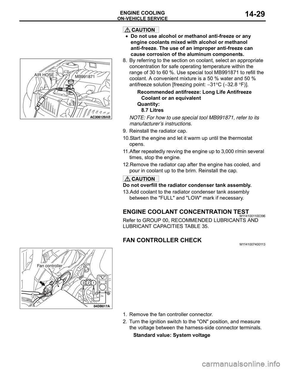
8. By referring to the section on coolant, select an appropriate
concentration for safe operating temperature within the
range of 30 to 60 %. Use special tool MB991871 to refill the
coolant. A convenient mixture is a 50 % water and 50 %
antifreeze solution [freezing point:
31C (32.8 F)].
Recommended antifreeze: Long Life Antifreeze
Coolant or an equivalent
Quantity:
8.7 Litres
NOTE: For how to use special tool MB991871, refer to its
manufacturer’s instructions.
9. Reinstall the radiator cap.
10.Start the engine and let it warm up until the thermostat
opens.
11.After repeatedly revving the engine up to 3,000 r/min several
times, stop the engine.
12.Remove the radiator cap after the engine has cooled, and
pour in coolant up to the brim. Reinstall the cap.
Do not overfill the radiator condenser tank assembly.
13.Add coolant to the radiator condenser tank assembly
between the "FULL" and "LOW" mark if necessary.
ENGINE COOLANT CONCENTRATION TESTM1141001100396
Refer to GROUP 00, RECOMMENDED LUBRICANTS AND
LUBRICANT CAPACITIES TABLE 35.
FAN CONTROLLER CHECKM1141007400113
1. Remove the fan controller connector.
2. Turn the ignition switch to the "ON" position, and measure
the voltage between the harness-side connector terminals.
Standard value: System voltage
Page 978 of 1500
16-1
GROUP 16
ENGINE
ELECTRICAL
CONTENTS
CHARGING SYSTEM . . . . . . . .
16-2
GENERAL DESCRIPTION . . . . . .
16-2
CHARGING SYSTEM DIAGNOSIS16-3
SPECIAL TOOL . . . . . . . . . . . . . . .16-6
ON-VEHICLE SERVICE. . . . . . . . .16-7
ALTERNATOR OUTPUT WIRE VOLTAGE
DROP TEST . . . . . . . . . . . . . . . . . . . . . 16-7
OUTPUT CURRENT TEST . . . . . . . . . . 16-8
REGULATED VOLTAGE TEST . . . . . . . 16-10
WAVE PATTERN CHECK USING AN
OSCILLOSCOPE . . . . . . . . . . . . . . . . . . 16-11
ALTERNATOR ASSEMBLY . . . . .16-14
REMOVAL AND INSTALLATION . . . . . 16-14
DISASSEMBLY AND ASSEMBLY. . . . . 16-15
INSPECTION . . . . . . . . . . . . . . . . . . . . . 16-17
STARTING SYSTEM . . . . . . . . .16-20
GENERAL DESCRIPTION . . . . . .
16-20
STARTING SYSTEM DIAGNOSIS . . . . 16-21
STARTER MOTOR ASSEMBLY . .16-23
REMOVAL AND INSTALLATION . . . . . 16-23
INSPECTION . . . . . . . . . . . . . . . . . . . . . 16-24
DISASSEMBLY AND ASSEMBLY. . . . . 16-26
INSPECTION . . . . . . . . . . . . . . . . . . . . . 16-28
IGNITION SYSTEM . . . . . . . . . . . . . .16-30GENERAL DESCRIPTION . . . . . . .
16-30
SPECIAL TOOLS . . . . . . . . . . . . . .16-30
ON-VEHICLE SERVICE . . . . . . . . .16-31
KNOCK CONTROL SYSTEM CHECK . . 16-31
IGNITION COIL CHECK. . . . . . . . . . . . . 16-31
SPARK PLUG TEST . . . . . . . . . . . . . . . 16-32
SPARK PLUG CHECK AND CLEANING16-32
CAMSHAFT POSITION SENSOR CHECK16-32
CRANKSHAFT POSITION SENSOR
CHECK . . . . . . . . . . . . . . . . . . . . . . . . . . 16-32
IGNITION COIL . . . . . . . . . . . . . . . .16-33
REMOVAL AND INSTALLATION . . . . . 16-33
CAMSHAFT POSITION SENSOR .16-34
REMOVAL AND INSTALLATION . . . . . 16-34
CRANKSHAFT POSITION SENSOR16-35
REMOVAL AND INSTALLATION . . . . . 16-35
KNOCK SENSOR . . . . . . . . . . . . . .16-36
REMOVAL AND INSTALLATION . . . . . 16-36
SPECIFICATIONS . . . . . . . . . . 16-38
FASTENER TIGHTENING
SPECIFICATIONS . . . . . . . . . . . . .
16-38
GENERAL SPECIFICATIONS . . . .16-38
SERVICE SPECIFICATIONS . . . . .16-39
Page 979 of 1500
16-2
CHARGING SYSTEM
GENERAL DESCRIPTIONM1161000100629
The charging system charges the battery with the
alternator output to keep the battery charged at a
constant level during varying electrical load.
OPERATION
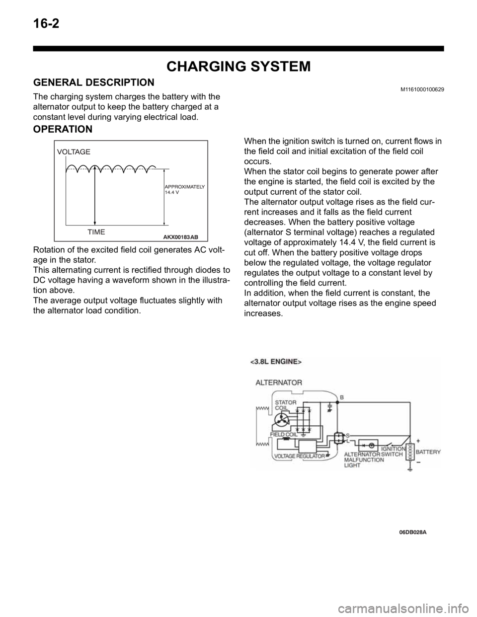
Rotation of the excited field coil generates AC volt-
age in the stator.
This alternating current is rectified through diodes to
DC voltage having a waveform shown in the illustra-
tion above.
The average output voltage fluctuates slightly with
the alternator load condition.When the ignition switch is turned on, current flows in
the field coil and initial excitation of the field coil
occurs.
When the stator coil begins to generate power after
the engine is started, the field coil is excited by the
output current of the stator coil.
The alternator output voltage rises as the field cur-
rent increases and it falls as the field current
decreases. When the battery positive voltage
(alternator S terminal voltage) reaches a regulated
voltage of approximately 14.4 V, the field current is
cut off. When the battery positive voltage drops
below the regulated voltage, the voltage regulator
regulates the output voltage to a constant level by
controlling the field current.
In addition, when the field current is constant, the
alternator output voltage rises as the engine speed
increases.
Page 980 of 1500
CHARGING SYSTEM
ENGINE ELECTRICAL16-3
CHARGING SYSTEM DIAGNOSISM1161000700427
TROUBLESHOOTING HINTS
Alternator malfunction light dose not go on when the ignition
switch is turned to ON, before the engine starts.
Check the bulb.
Alternator malfunction light dose not switch off after the engine
starts.
Check the IC voltage regulator inside the
alternatoralternator.
Discharged or overcharged battery.
Check the IC voltage regulator inside the alternator.
The alternator malfunction light illuminates dimly.
Check the diode (inside the combination meter) for a
short-circuit.
TROUBLESHOOTING GUIDE
The charging system troubleshooting guide is shown in the fol-
lowing steps.
STEP 1.
Q: Is the battery in good condition? (Refer to GROUP 54A,
Chassis Electrical
Battery On-vehicle Service
Battery Check P.54A-5.)
YES : Go to Step 2.
NO : Charge or replace the battery.
STEP 2.
Q: Is the alternator drive belt in good condition? (Refer to
GROUP 00, General
Maintenance Service Drive Belts
(For Alternator, Power Steering Pump and Air
Conditioning) (Check) P.00-39.)
YES : Go to Step 3.
NO : Adjust the belt tension or replace the belt.
STEP 3.
Q: Does the alternator malfunction light come on when the
ignition switch is turned on?
YES : Go to Step 4.
NO :
Check the ignition switch. (Refer to GROUP 54A,
Chassis Electrical
Ignition Switch Ignition
Switch
Inspection P.54A-44.)
Check for burnt-out alternator malfunction light.
Check the alternator. (Refer to Charging System
Alternator Assembly
Inspection P.16-17.)
Check the alternator malfunction light-related
circuits.
Page 984 of 1500
CHARGING SYSTEM
ENGINE ELECTRICAL16-7
ON-VEHICLE SERVICE
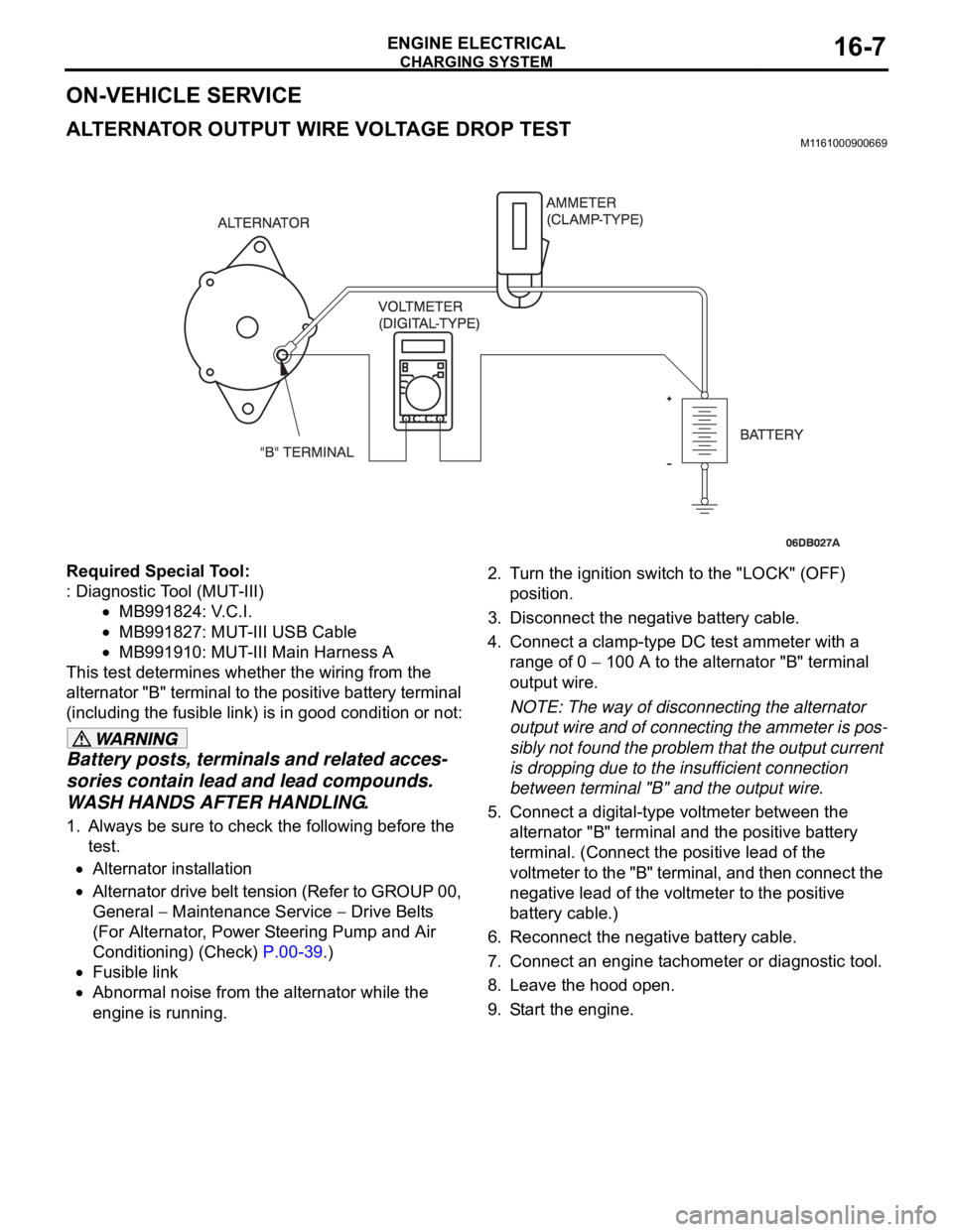
ALTERNATOR OUTPUT WIRE VOLTAGE DROP TESTM1161000900669
Required Special Tool:
: Diagnostic Tool (MUT-III)
MB991824: V.C.I.
MB991827: MUT-III USB Cable
MB991910: MUT-III Main Harness A
This test determines whether the wiring from the
alternator "B" terminal to the positive battery terminal
(including the fusible link) is in good condition or not:
Battery posts, terminals and related acces-
sories contain lead and lead compounds.
WASH HANDS AFTER HANDLING.
1. Always be sure to check the following before the
test.
Alternator installation
Alternator drive belt tension (Refer to GROUP 00,
General
Maintenance Service Drive Belts
(For Alternator, Power Steering Pump and Air
Conditioning) (Check) P.00-39.)
Fusible link
Abnormal noise from the alternator while the
engine is running.2. Turn the ignition switch to the "LOCK" (OFF)
position.
3. Disconnect the negative battery cable.
4. Connect a clamp-type DC test ammeter with a
range of 0
100 A to the alternator "B" terminal
output wire.
NOTE: The way of disconnecting the alternator
output wire and of connecting the ammeter is pos-
sibly not found the problem that the output current
is dropping due to the insufficient connection
between terminal "B" and the output wire.
5. Connect a digital-type voltmeter between the
alternator "B" terminal and the positive battery
terminal. (Connect the positive lead of the
voltmeter to the "B" terminal, and then connect the
negative lead of the voltmeter to the positive
battery cable.)
6. Reconnect the negative battery cable.
7. Connect an engine tachometer or diagnostic tool.
8. Leave the hood open.
9. Start the engine.
Page 985 of 1500
CHARGING SYSTEM
ENGINE ELECTRICAL16-8
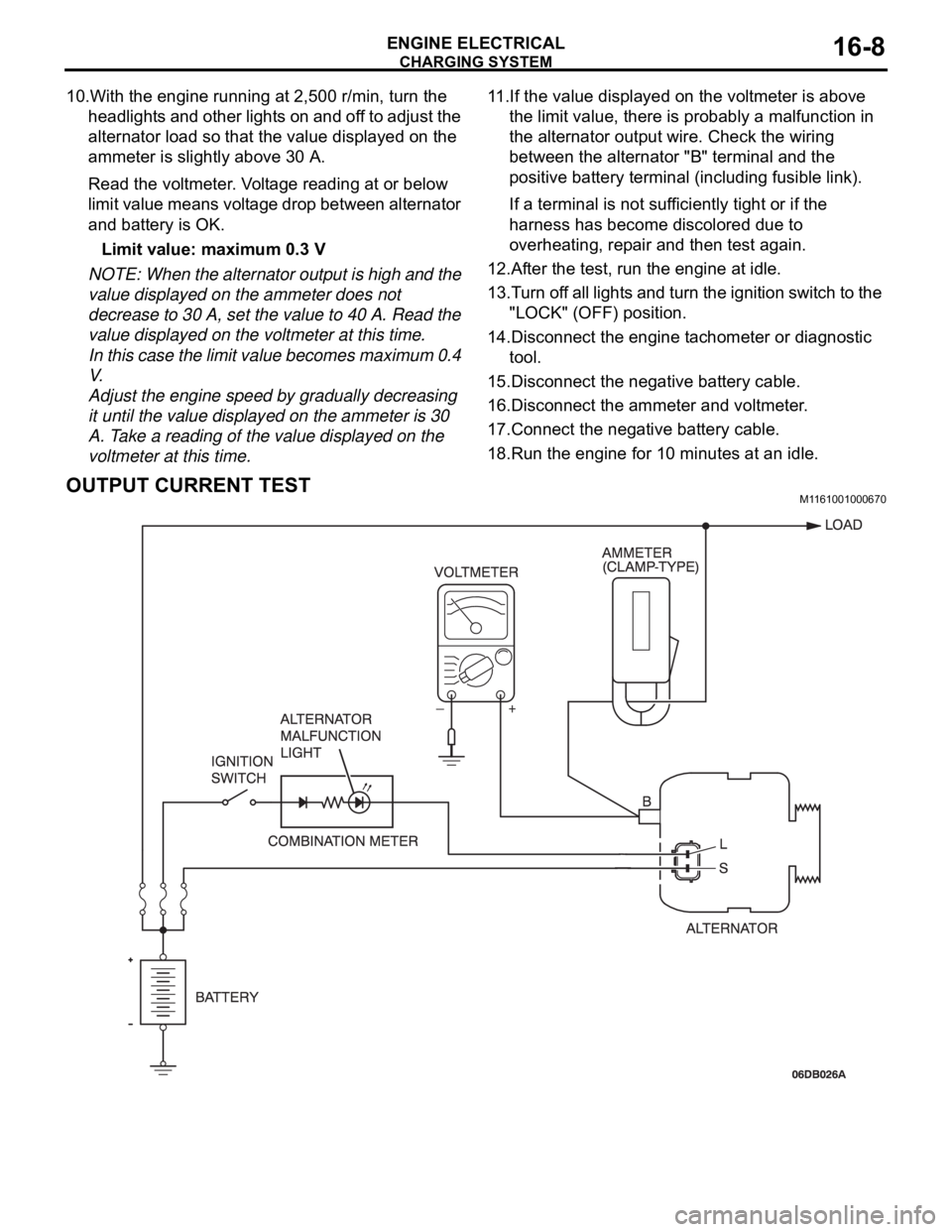
10.With the engine running at 2,500 r/min, turn the
headlights and other lights on and off to adjust the
alternator load so that the value displayed on the
ammeter is slightly above 30 A.
Read the voltmeter. Voltage reading at or below
limit value means voltage drop between alternator
and battery is OK.
Limit value: maximum 0.3 V
NOTE: When the alternator output is high and the
value displayed on the ammeter does not
decrease to 30 A, set the value to 40 A. Read the
value displayed on the voltmeter at this time.
In this case the limit value becomes maximum 0.4
V.
Adjust the engine speed by gradually decreasing
it until the value displayed on the ammeter is 30
A. Take a reading of the value displayed on the
voltmeter at this time.11.If the value displayed on the voltmeter is above
the limit value, there is probably a malfunction in
the alternator output wire. Check the wiring
between the alternator "B" terminal and the
positive battery terminal (including fusible link).
If a terminal is not sufficiently tight or if the
harness has become discolored due to
overheating, repair and then test again.
12.After the test, run the engine at idle.
13.Turn off all lights and turn the ignition switch to the
"LOCK" (OFF) position.
14.Disconnect the engine tachometer or diagnostic
tool.
15.Disconnect the negative battery cable.
16.Disconnect the ammeter and voltmeter.
17.Connect the negative battery cable.
18.Run the engine for 10 minutes at an idle.
OUTPUT CURRENT TESTM1161001000670