Ignition MITSUBISHI 380 2005 Workshop Manual
[x] Cancel search | Manufacturer: MITSUBISHI, Model Year: 2005, Model line: 380, Model: MITSUBISHI 380 2005Pages: 1500, PDF Size: 47.87 MB
Page 826 of 1500
AUTO A/C DIAGNOSIS
HEATER, AIR CONDITIONING AND VENTILATION55-125
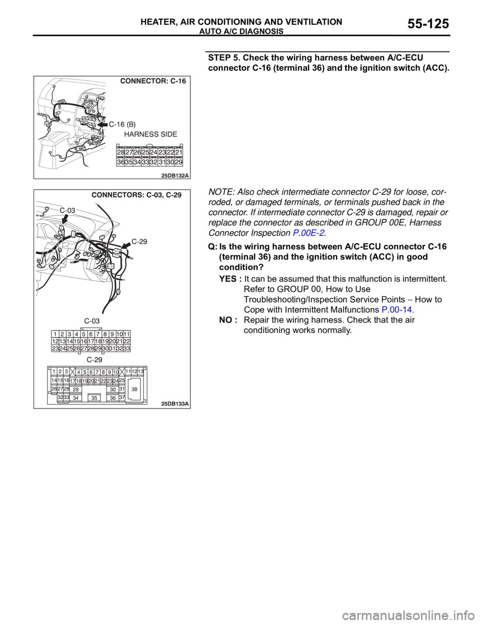
STEP 5. Check the wiring harness between A/C-ECU
connector C-16 (terminal 36) and the ignition switch (ACC).
NOTE: Also check intermediate connector C-29 for loose, cor-
roded, or damaged terminals, or terminals pushed back in the
connector. If intermediate connector C-29 is damaged, repair or
replace the connector as described in GROUP 00E, Harness
Connector Inspection P.00E-2.
Q: Is the wiring harness between A/C-ECU connector C-16
(terminal 36) and the ignition switch (ACC) in good
condition?
YES : It can be assumed that this malfunction is intermittent.
Refer to GROUP 00, How to Use
Troubleshooting/Inspection Service Points
How to
Cope with Intermittent Malfunctions P.00-14.
NO : Repair the wiring harness. Check that the air
conditioning works normally.
Page 830 of 1500
AUTO A/C DIAGNOSIS
HEATER, AIR CONDITIONING AND VENTILATION55-129
DIAGNOSIS
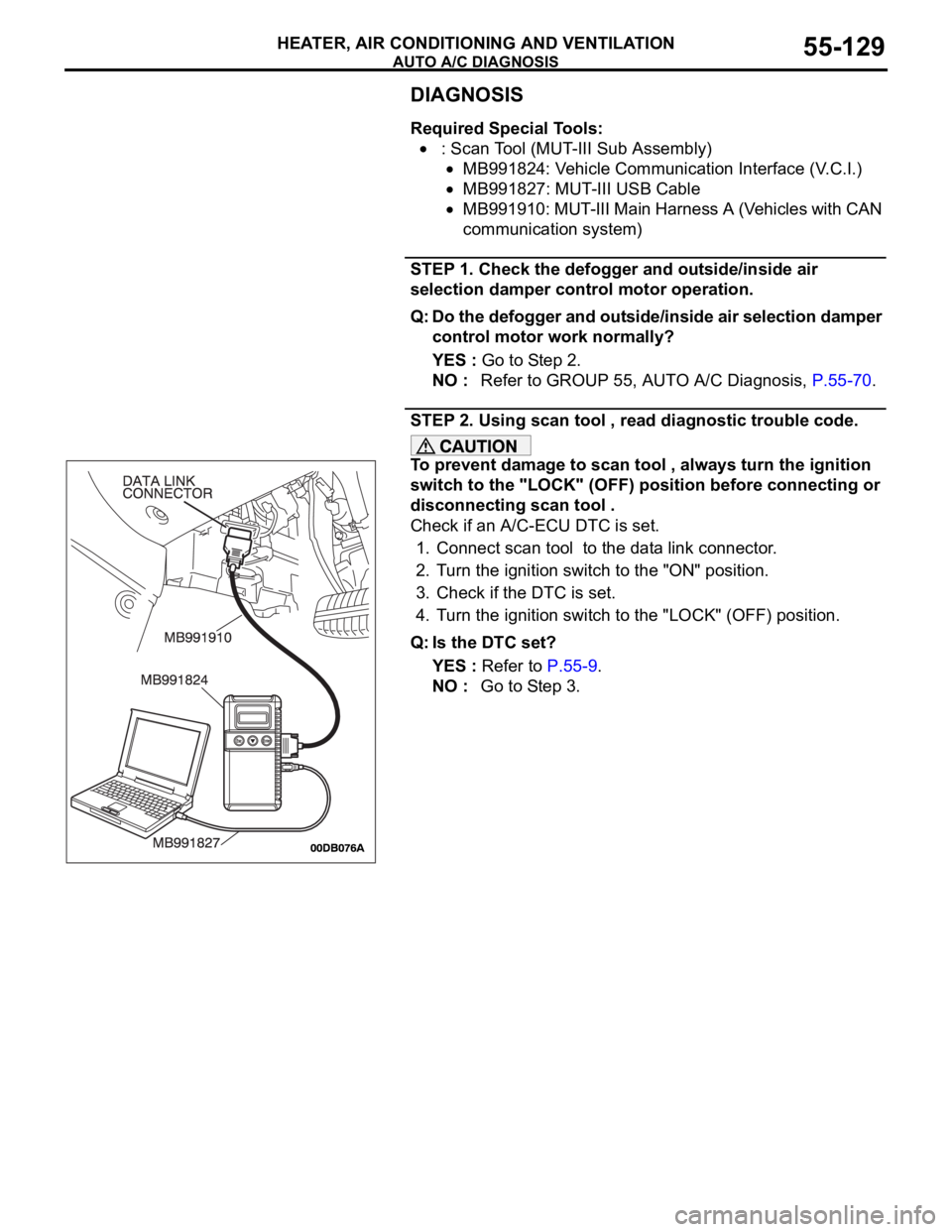
Required Special Tools:
: Scan Tool (MUT-III Sub Assembly)
MB991824: Vehicle Communication Interface (V.C.I.)
MB991827: MUT-III USB Cable
MB991910: MUT-III Main Harness A (Vehicles with CAN
communication system)
STEP 1. Check the defogger and outside/inside air
selection damper control motor operation.
Q: Do the defogger and outside/inside air selection damper
control motor work normally?
YES : Go to Step 2.
NO : Refer to GROUP 55, AUTO A/C Diagnosis, P.55-70.
STEP 2. Using scan tool , read diagnostic trouble code.
To prevent damage to scan tool , always turn the ignition
switch to the "LOCK" (OFF) position before connecting or
disconnecting scan tool .
Check if an A/C-ECU DTC is set.
1. Connect scan tool to the data link connector.
2. Turn the ignition switch to the "ON" position.
3. Check if the DTC is set.
4. Turn the ignition switch to the "LOCK" (OFF) position.
Q: Is the DTC set?
YES : Refer to P.55-9.
NO : Go to Step 3.
Page 831 of 1500
AUTO A/C DIAGNOSIS
HEATER, AIR CONDITIONING AND VENTILATION55-130
STEP 3. Using scan tool , check data list item 67: Photo
sensor.
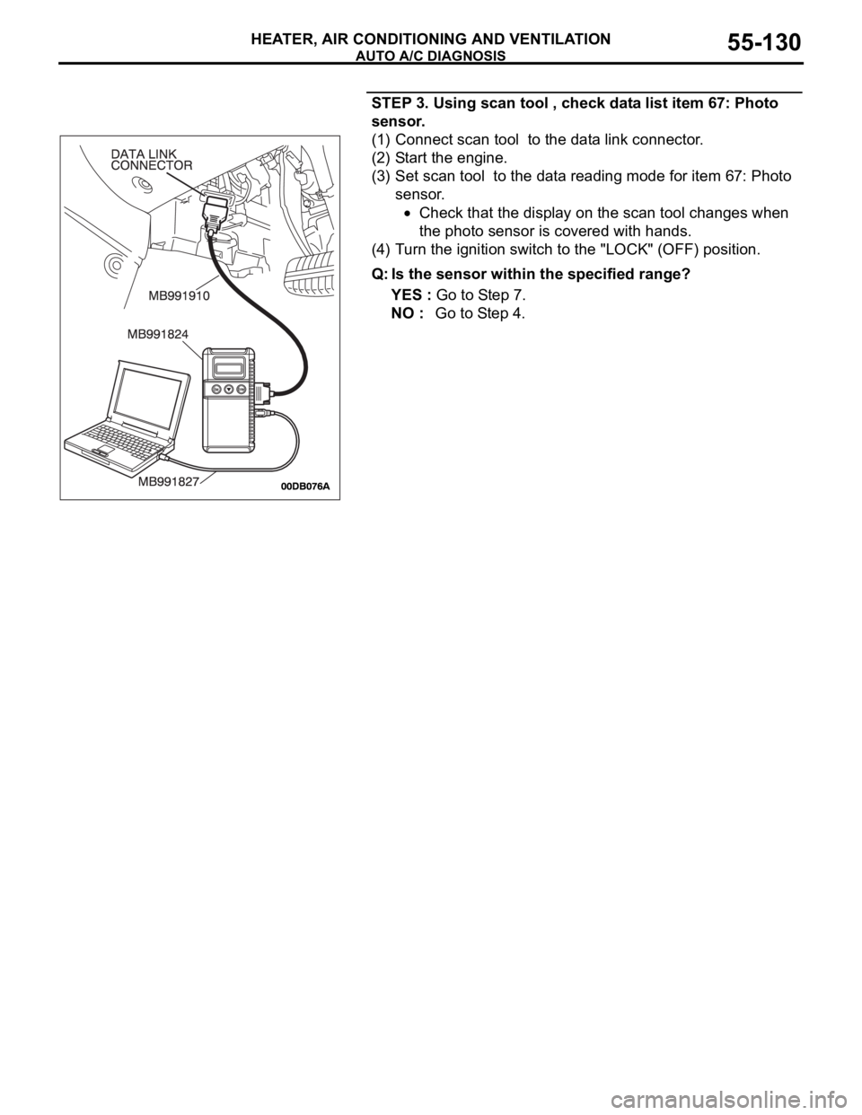
(1) Connect scan tool to the data link connector.
(2) Start the engine.
(3) Set scan tool to the data reading mode for item 67: Photo
sensor.
Check that the display on the scan tool changes when
the photo sensor is covered with hands.
(4) Turn the ignition switch to the "LOCK" (OFF) position.
Q: Is the sensor within the specified range?
YES : Go to Step 7.
NO : Go to Step 4.
Page 834 of 1500

AUTO A/C DIAGNOSIS
HEATER, AIR CONDITIONING AND VENTILATION55-133
DATA LIST REFERENCE TABLEM1554005100136
MUT-III
DIAGNOSTIC
TOOL DISPLAYITEM
NO.INSPECTION ITEM INSPECTION REQUIREMENT NORMAL VALUE
Inside
temperature
sensor59 Interior temperature
sensorIgnition switch: ON Inside air
temperature and
temperature
displayed on the
diagnostic tool are
identical.
Outside
temperature
sensor58 Outside temperature
sensorIgnition switch: ON Outside air
temperature and
temperature
displayed on the
diagnostic tool are
identical.
Air thermo sensor 20 Air thermo sensor Ignition switch: ON The temperature
measured behind
the evaporator
matches the
displayed value on
the diagnostic tool
while the engine is
cold.
Pressure sensor 61 A/C pressure sensor Ignition switch: ON Measured refrigerant
pressure is nearly
equal to the value
shown on the
diagnostic tool
(MPa).
Water
temperature
sensor62 Engine coolant
temperature sensor
(Data received by
CAN
Communication)Ignition switch: ON Engine coolant
temperature and
temperature
displayed on the
diagnostic tool are
identical.
Photo sensor 67 Photo sensor Ignition switch: ON Amount of light is
proportional to
voltage displayed on
the diagnostic tool.
Air mix
potentiometer63 Air mixing damper
control motor
potentiometerIgnition switch: ON Damper
positionOpening degree (V)
MAX. HOT Approx. 5
MAX. COOL Approx. 0
Air mix
potentiometer
(Target)64 Target value for air
mixing damper
control motor
potentiometerIgnition switch: ON Damper
positionOpening degree (V)
MAX. HOT Approx. 5
MAX. COOL Approx. 0
Page 835 of 1500

AUTO A/C DIAGNOSIS
HEATER, AIR CONDITIONING AND VENTILATION55-134
Air outlet c/o
potentiometer55 Mode selection
damper control
motor potentiometerIgnition switch: ON Damper
positionOpening degree (V)
FA C E A p pr o x . 5
FOOT Approx. 3.75
FOOT/DEF. Approx. 2.5
DEF. Approx. 1.75
Air outlet c/o
potentiometer
(target)56 Target value for
mode selection
damper control
motor potentiometerIgnition switch: ON Damper
positionOpening degree (V)
FA C E A p pr o x . 5
FOOT Approx. 3.75
FOOT/DEF. Approx. 2.5
DEF. Approx. 1.75
In/out air
changeover
damper motor65 Outside/inside air
selection damper
control motorIgnition switch: ON Damper set
positionDamper position
Fresh air
positionFRESH
Air recirculation
positionRECIRC
Front blower fan 68 Blower motor Ignition switch: ON The actual air
volume (blower
motor speed)
corresponds to the
air volume shown on
the diagnostic tool.
Front blower
motor voltage 71 Blower motor Ignition switch: ON The air volume set
by the heater control
corresponds to the
value shown on the
diagnostic tool. (V)
Air conditioning
switch state1 Air conditioning
switchIgnition switch: ON Air conditioning
switch: ONDiagnostic tool
indication: "pressed"
Air conditioning
switch: OFFDiagnostic tool
indication: "release"
Rear defogger
switch state7 Rear window
defogger switchIgnition switch: ON Rear window
defogger
switch: ONDiagnostic tool
indication: "pressed"
Rear window
defogger
switch: OFFDiagnostic tool
indication: "release"
Refrigerant
pressure73 Refrigerant pressure Ignition switch: ON The diagnostic tool
indication is normal MUT-III
DIAGNOSTIC
TOOL DISPLAYITEM
NO.INSPECTION ITEM INSPECTION REQUIREMENT NORMAL VALUE
Page 836 of 1500

AUTO A/C DIAGNOSIS
HEATER, AIR CONDITIONING AND VENTILATION55-135
Temperature
setting23 Temperature setting
actualIgnition switch: ON The actual setting
corresponds with
diagnostic tool
display.
Vehicle speed 26 Actual vehicle speed Ignition switch: ON The vehicle speed
corresponds with
diagnostic tool
display.
A/C compressor
drive request27 Compressor clutch Engine: ON
Compressor:
ONDiagnostic tool
indication: "ON"
Compressor:
OFFDiagnostic tool
indication: "OFF"
Illumination 15 Display lighting Ignition switch: ON
Lights: ON
Diagnostic tool
indication: "ON"
Lights: OFF
Diagnostic tool
indication: "OFF"
Engine speed 23 Actual engine speed Engine: ON The engine speed
corresponds with
diagnostic tool
display.
In/out air select
switch state3 In/out air select
switch Ignition switch: ON In/out air
switch: ONDiagnostic tool
indication: "pressed"
In/out air
switch: OFFDiagnostic tool
indication: "release"
Rear defogger
relay72 Rear defogger relay Ignition switch: ON
Rear defogger:
ONDiagnostic tool
indication: "ON"
Rear defogger:
OFFDiagnostic tool
indication: "OFF" MUT-III
DIAGNOSTIC
TOOL DISPLAYITEM
NO.INSPECTION ITEM INSPECTION REQUIREMENT NORMAL VALUE
Page 838 of 1500

AUTO A/C DIAGNOSIS
HEATER, AIR CONDITIONING AND VENTILATION55-137
CHECK AT A/C-ECU TERMINALM1552010300572
TERMINAL
NO.CHECK ITEM CHECKING REQUIREMENTS NORMAL CONDITION
1 Air mixing damper control motor When the air mix damper is
moved to the MAX. COOL
position. 10 V
When the air mix damper is
moved to the MAX. HOT
position. 0.5 V
2 Air mixing damper control motor When the air mix damper is
moved to the MAX. COOL
position. 0.5 V
When the air mix damper is
moved to the MAX. HOT
position. 10 V
3 Back-up power supply Always Battery positive voltage
4 Mode selection damper control
motor (DEF)When the damper is moved to
the FACE position. 0.5 V
When the damper is moved to
the DEF position. 10 V
5 Outside/inside air selection
damper control motor (outside)When the damper is moved to
the inside air recirculation
position.0.5 V
When the damper is moved to
the outside air induction
position.0 V (when the motor is
stopped)
6 Outside/inside air selection
damper control motor (inside)When the damper is moved to
the inside air recirculation
position.0 V (when the motor is
stopped)
When the damper is moved to
the outside air induction
position.0.5 V
8 Rear defogger relay Ignition switch: ON Battery positive voltage
9 Front blower relay Ignition switch: ON Battery positive voltage
10 A/C compressor relay A/C compressor relay: ON Battery positive voltage
11 Mode selection damper control
motor (FACE)When the damper is moved to
the FACE position. 10 V
When the damper is moved to
the DEF position. 0.5 V
12 A/C pressure sensor Ignition switch: ON 5 V
Page 839 of 1500

AUTO A/C DIAGNOSIS
HEATER, AIR CONDITIONING AND VENTILATION55-138
16 Potentiometer power supply Ignition switch: ON 5 V
17 Power transistor (BASE) When the blower speed
selection dial shows Maximum
air volume.1 V
18 Power transistor
(COLLECTOR)When the blower speed
selection dial shows Maximum
air volume.12.1 V
19 Photo sensor Ignition switch: ON 5 V
20 Sensors and potentiometers
groundAlways 0 V
21 Mode selection damper control
motor potentiometer inputWhen the damper is moved to
the FACE position. 4 V
22 Interior temperature sensor Ignition switch: ON 5 V
23 Ambient temperature sensor
inputWhen sensor temperature is
25
C (77F) [4 k]1.9 V
24 Air thermo sensor input When sensor temperature is
25
C (77F) [1.5 k]2.2 V
25 Photo sensor ground Ignition switch: ON 0 V
26 A/C pressure sensor at 2.6 MPa 3.9 V
27 Ground Always 0 V
28 Power supply to the ignition
switch (IG2)Ignition switch: ON Battery positive voltage
29 Air mixing damper control motor
potentiometer inputWhen the damper door is
moved to the MAX. HOT
position.1.4 V
30 Illumination ground Always 0 V
31 ILL power supply Lighting switch: ON Battery positive voltage
34 A/C pressure sensor ground Always 0 V
36 Power supply to the ignition
switch (ACC)Ignition switch: ON Battery positive voltage TERMINAL
NO.CHECK ITEM CHECKING REQUIREMENTS NORMAL CONDITION
Page 907 of 1500
HOW TO DIAGNOSE
GENERAL
5. Ohmmeter
An ohmmeter is used to check continuity or measure
resistance of a switch or coil. If the measuring range has
been changed, the zero point must be adjusted before
measurement.
CHECKING FUSESM1001005000044
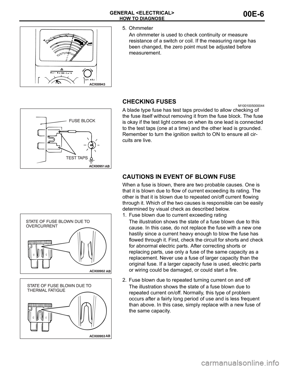
A blade type fuse has test taps provided to allow checking of
the fuse itself without removing it from the fuse block. The fuse
is okay if the test light comes on when its one lead is connected
to the test taps (one at a time) and the other lead is grounded.
Remember to turn the ignition switch to ON to ensure all cir-
cuits are live.
CAUTIONS IN EVENT OF BLOWN FUSE
When a fuse is blown, there are two probable causes. One is
that it is blown due to flow of current exceeding its rating. The
other is that it is blown due to repeated on/off current flowing
through it. Which of the two causes is responsible can be easily
determined by visual check as described below.
1. Fuse blown due to current exceeding rating
The illustration shows the state of a fuse blown due to this
cause. In this case, do not replace the fuse with a new one
hastily since a current heavy enough to blow the fuse has
flowed through it. First, check the circuit for shorts and check
for abnormal electric parts. After correcting shorts or
replacing parts, use only a fuse of the same capacity as a
replacement. Never use a fuse of larger capacity than the
original fuse. If a larger capacity fuse is used, electric parts
or wiring could be damaged, or could start a fire.
2. Fuse blown due to repeated turning current on and off
The illustration shows the state of a fuse blown due to
repeated current on/off. Normally, this type of problem
occurs after a fairly long period of use and is less frequent
than above. In this case, simply replace with a new fuse of
the same capacity.
Page 921 of 1500
ENGINE COOLING DIAGNOSIS
ENGINE COOLING14-6
DIAGNOSIS
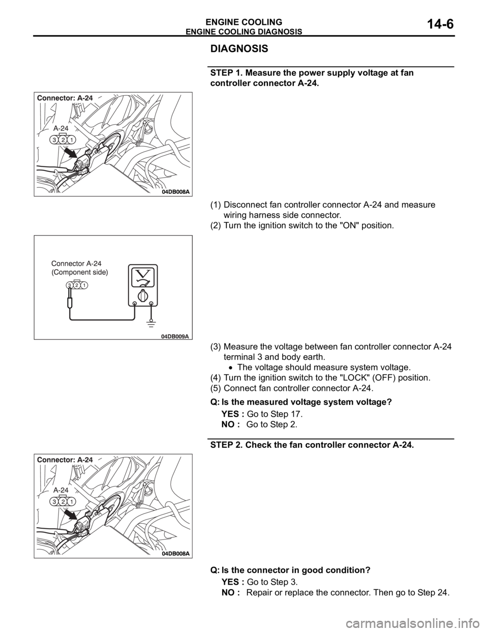
STEP 1. Measure the power supply voltage at fan
controller connector A-24.
(1) Disconnect fan controller connector A-24 and measure
wiring harness side connector.
(2) Turn the ignition switch to the "ON" position.
(3) Measure the voltage between fan controller connector A-24
terminal 3 and body earth.
The voltage should measure system voltage.
(4) Turn the ignition switch to the "LOCK" (OFF) position.
(5) Connect fan controller connector A-24.
Q: Is the measured voltage system voltage?
YES : Go to Step 17.
NO : Go to Step 2.
STEP 2. Check the fan controller connector A-24.
Q: Is the connector in good condition?
YES : Go to Step 3.
NO : Repair or replace the connector. Then go to Step 24.