diagram MITSUBISHI 380 2005 Owner's Manual
[x] Cancel search | Manufacturer: MITSUBISHI, Model Year: 2005, Model line: 380, Model: MITSUBISHI 380 2005Pages: 1500, PDF Size: 47.87 MB
Page 106 of 1500
SYMPTOM PROCEDURES
SIMPLIFIED WIRING SYSTEM (SWS)54B-106
INSPECTION PROCEDURE B-4: Tone Alarm: Door ajar Warning Buzzer Function does not Work
Normally.
NOTE: This troubleshooting procedure requires the
use of diagnostic tool MB991958 and SWS monitor
kit MB991813. For details on how to use the SWS
monitor, refer to "How to connect SWS monitor
P.54B-13."
.
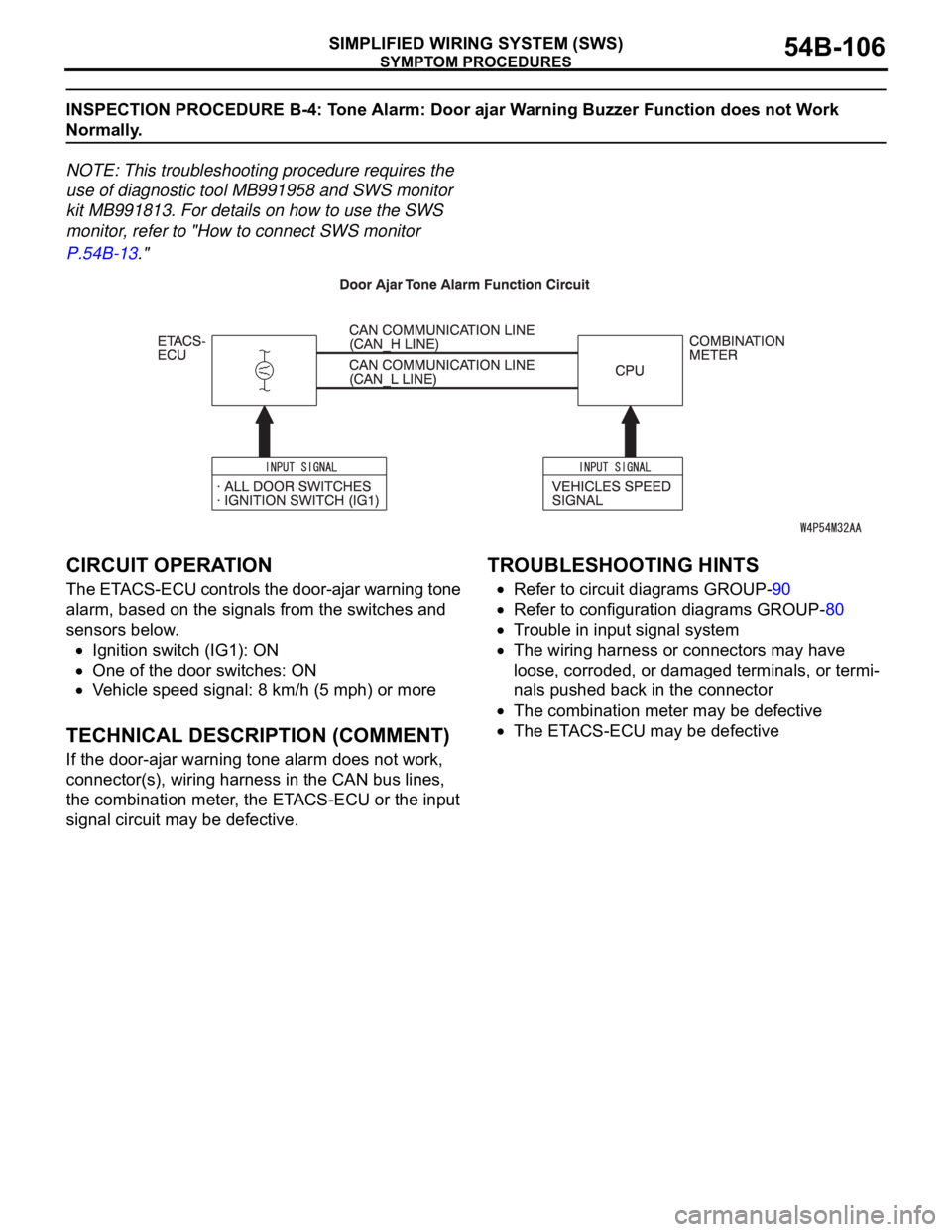
CIRCUIT OPERATION
The ETACS-ECU controls the door-ajar warning tone
alarm, based on the signals from the switches and
sensors below.
Ignition switch (IG1): ON
One of the door switches: ON
Vehicle speed signal: 8 km/h (5 mph) or more
.
TECHNICAL DESCRIPTION (COMMENT)
If the door-ajar warning tone alarm does not work,
connector(s), wiring harness in the CAN bus lines,
the combination meter, the ETACS-ECU or the input
signal circuit may be defective.
.
TROUBLESHOOTING HINTS
Refer to circuit diagrams GROUP-90
Refer to configuration diagrams GROUP-80
Trouble in input signal system
The wiring harness or connectors may have
loose, corroded, or damaged terminals, or termi-
nals pushed back in the connector
The combination meter may be defective
The ETACS-ECU may be defective
Page 112 of 1500
SYMPTOM PROCEDURES
SIMPLIFIED WIRING SYSTEM (SWS)54B-112
INSPECTION PROCEDURE B-5: Tone Alarm: The Multi center Display does not Sound Normally When
it is Operated.
NOTE: This troubleshooting procedure requires the
use of diagnostic tool MB991958 and SWS monitor
kit MB991813. For details on how to use the SWS
monitor, refer to "How to connect SWS monitor
P.54B-13."
.
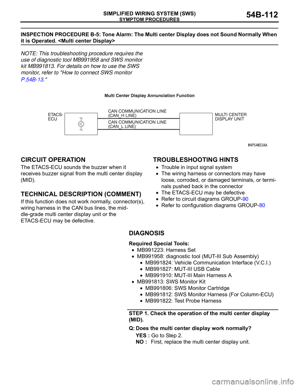
CIRCUIT OPERATION
The ETACS-ECU sounds the buzzer when it
receives buzzer signal from the multi center display
(MID).
.
TECHNICAL DESCRIPTION (COMMENT)
If this function does not work normally, connector(s),
wiring harness in the CAN bus lines, the mid-
dle-grade multi center display unit or the
ETACS-ECU may be defective.
.
TROUBLESHOOTING HINTS
Trouble in input signal system
The wiring harness or connectors may have
loose, corroded, or damaged terminals, or termi-
nals pushed back in the connector
The ETACS-ECU may be defective
Refer to circuit diagrams GROUP-90
Refer to configuration diagrams GROUP-80
DIAGNOSIS
Required Special Tools:
MB991223: Harness Set
MB991958: diagnostic tool (MUT-III Sub Assembly)
MB991824: Vehicle Communication Interface (V.C.I.)
MB991827: MUT-III USB Cable
MB991910: MUT-III Main Harness A
MB991813: SWS Monitor Kit
MB991806: SWS Monitor Cartridge
MB991812: SWS Monitor Harness (For Column-ECU)
MB991822: Test Probe Harness
STEP 1. Check the operation of the multi center display
(MID).
Q: Does the multi center display work normally?
YES : Go to Step 2.
NO : First, replace the multi center display unit.
Page 116 of 1500
SYMPTOM PROCEDURES
SIMPLIFIED WIRING SYSTEM (SWS)54B-116
INSPECTION PROCEDURE B-6: Tone Alarm: Turn-signal Lamp Buzzer Function does not Work
Normally.
NOTE: This troubleshooting procedure requires use
of diagnostic tool MB991958 and SWS monitor kit
MB991813. For details on how to use the SWS mon-
itor, refer to "How to connect SWS monitor
P.54B-13."
.
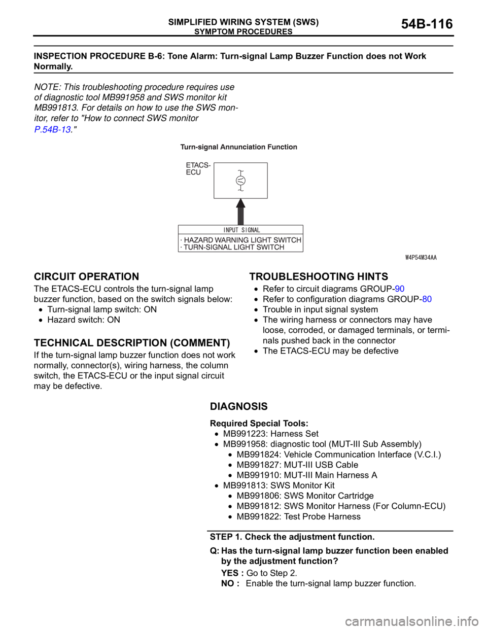
CIRCUIT OPERATION
The ETACS-ECU controls the turn-signal lamp
buzzer function, based on the switch signals below:
Turn-signal lamp switch: ON
Hazard switch: ON
.
TECHNICAL DESCRIPTION (COMMENT)
If the turn-signal lamp buzzer function does not work
normally, connector(s), wiring harness, the column
switch, the ETACS-ECU or the input signal circuit
may be defective.
.
TROUBLESHOOTING HINTS
Refer to circuit diagrams GROUP-90
Refer to configuration diagrams GROUP-80
Trouble in input signal system
The wiring harness or connectors may have
loose, corroded, or damaged terminals, or termi-
nals pushed back in the connector
The ETACS-ECU may be defective
DIAGNOSIS
Required Special Tools:
MB991223: Harness Set
MB991958: diagnostic tool (MUT-III Sub Assembly)
MB991824: Vehicle Communication Interface (V.C.I.)
MB991827: MUT-III USB Cable
MB991910: MUT-III Main Harness A
MB991813: SWS Monitor Kit
MB991806: SWS Monitor Cartridge
MB991812: SWS Monitor Harness (For Column-ECU)
MB991822: Test Probe Harness
STEP 1. Check the adjustment function.
Q: Has the turn-signal lamp buzzer function been enabled
by the adjustment function?
YES : Go to Step 2.
NO : Enable the turn-signal lamp buzzer function.
Page 122 of 1500
SYMPTOM PROCEDURES
SIMPLIFIED WIRING SYSTEM (SWS)54B-122
INSPECTION PROCEDURE C-1: Central Door Locking System: The Central Door Locking System
does not Work at all.
NOTE: This troubleshooting procedure requires the
use of diagnostic tool MB991958 and SWS monitor
kit MB991813. For details on how to use the SWS
monitor, refer to "How to connect SWS monitor
P.54B-13."
.
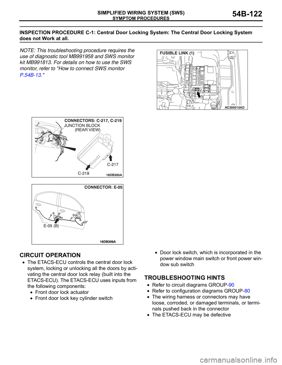
CIRCUIT OPERATION
The ETACS-ECU controls the central door lock
system, locking or unlocking all the doors by acti-
vating the central door lock relay (built into the
ETACS-ECU). The ETACS-ECU uses inputs from
the following components:
Front door lock actuator
Front door lock key cylinder switch
Door lock switch, which is incorporated in the
power window main switch or front power win-
dow sub switch
.
TROUBLESHOOTING HINTS
Refer to circuit diagrams GROUP-90
Refer to configuration diagrams GROUP-80
The wiring harness or connectors may have
loose, corroded, or damaged terminals, or termi-
nals pushed back in the connector
The ETACS-ECU may be defective
Page 130 of 1500
SYMPTOM PROCEDURES
SIMPLIFIED WIRING SYSTEM (SWS)54B-130
.
TECHNICAL DESCRIPTION (COMMENT)
The wiring harness between the door lock actuator or
the ETACS-ECU and the door lock actuator may be
defective.
.
TROUBLESHOOTING HINTS
Refer to circuit diagrams GROUP-90
Refer to configuration diagrams GROUP-80
The front door lock actuator or rear door lock
actuator may be defective
The wiring harness or connectors may have
loose, corroded, or damaged terminals, or termi-
nals pushed back in the connector
The ETACS-ECU may be defective
DIAGNOSIS
Required Special Tool:
MB991223: Harness Set
STEP 1. Check which door lock is defective.
Q: Which of the door locks is defective?
Driver's door : Go to Step 2.
Front passenger's door : Go to Step 7.
Rear door (LH) : Go to Step 11.
Rear door (RH) : Go to Step 15.
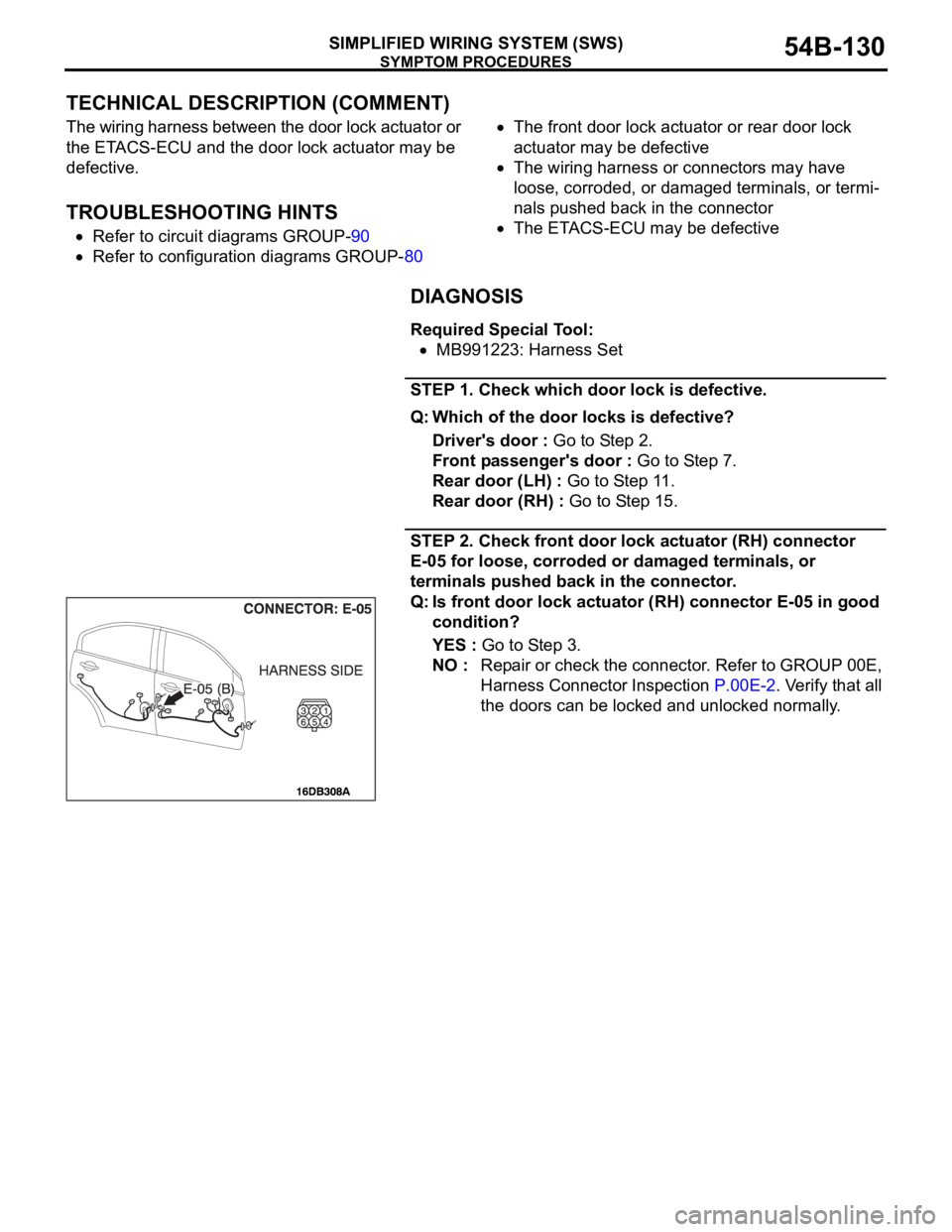
STEP 2. Check front door lock actuator (RH) connector
E-05 for loose, corroded or damaged terminals, or
terminals pushed back in the connector.
Q: Is front door lock actuator (RH) connector E-05 in good
condition?
YES : Go to Step 3.
NO : Repair or check the connector. Refer to GROUP 00E,
Harness Connector Inspection P.00E-2. Verify that all
the doors can be locked and unlocked normally.
Page 142 of 1500
SYMPTOM PROCEDURES
SIMPLIFIED WIRING SYSTEM (SWS)54B-142
INSPECTION PROCEDURE C-3: Central Door Locking System: All the Doors do not Lock or Unlock
with just the Door Lock Switch Operation.
.
TECHNICAL DESCRIPTION (COMMENT)
The door lock switch (incorporated in the power win-
dow main switch and front power window sub switch)
or the ETACS-ECU may be defective.
.
TROUBLESHOOTING HINTS
Refer to circuit diagrams GROUP-90
Refer to configuration diagrams GROUP-80
Trouble in input signal system
The wiring harness or connectors may have
loose, corroded, or damaged terminals, or termi-
nals pushed back in the connector
The ETACS-ECU may be defective
DIAGNOSIS
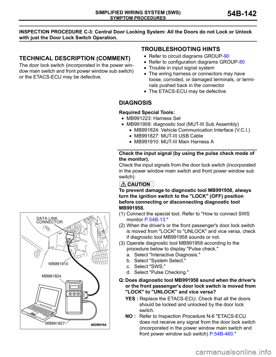
Required Special Tools:
MB991223: Harness Set
MB991958: diagnostic tool (MUT-III Sub Assembly)
MB991824: Vehicle Communication Interface (V.C.I.)
MB991827: MUT-III USB Cable
MB991910: MUT-III Main Harness A
Check the input signal (by using the pulse check mode of
the monitor).
Check the input signals from the door lock switch (incorporated
in the power window main switch and front power window sub
switch):
To prevent damage to diagnostic tool MB991958, always
turn the ignition switch to the "LOCK" (OFF) position
before connecting or disconnecting diagnostic tool
MB991958.
(1) Connect the special tool. Refer to "How to connect SWS
monitor P.54B-13."
(2) When the driver's or the front passenger's door lock switch
is moved from "LOCK" to "UNLOCK" and vice versa, check
if diagnostic tool MB991958 sounds or not.
(3) Operate diagnostic tool MB991958 according to the
procedure below to display "Pulse check."
a. Select "Interactive Diagnosis."
b. Select "System Select."
c. Select "SWS."
d. Select "Pulse Checking."
Q: Does diagnostic tool MB991958 sound when the driver's
or the front passenger's door lock switch is moved from
"LOCK" to "UNLOCK" and vice versa?
YES : Replace the ETACS-ECU. Check that all the doors
should be locked and unlocked by the door lock
switch.
NO : Refer to Inspection Procedure N-6 "ETACS-ECU
does not receive any signal from the door lock switch
(incorporated in the power window main switch and
front power window sub switch) P.54B-460."
Page 143 of 1500
SYMPTOM PROCEDURES
SIMPLIFIED WIRING SYSTEM (SWS)54B-143
INSPECTION PROCEDURE C-4: Central Door Locking System: All the Doors do not Lock or Unlock
with just the Door Lock Key Cylinder Key Operation.
.
TECHNICAL DESCRIPTION (COMMENT)
The door lock key cylinder switch or the ETACS-ECU
may be defective.
.
TROUBLESHOOTING HINTS
Refer to circuit diagrams GROUP-90
Refer to configuration diagrams GROUP-80
Trouble in input signal system
The wiring harness or connectors may have
loose, corroded, or damaged terminals, or termi-
nals pushed back in the connector
The ETACS-ECU may be defective
DIAGNOSIS
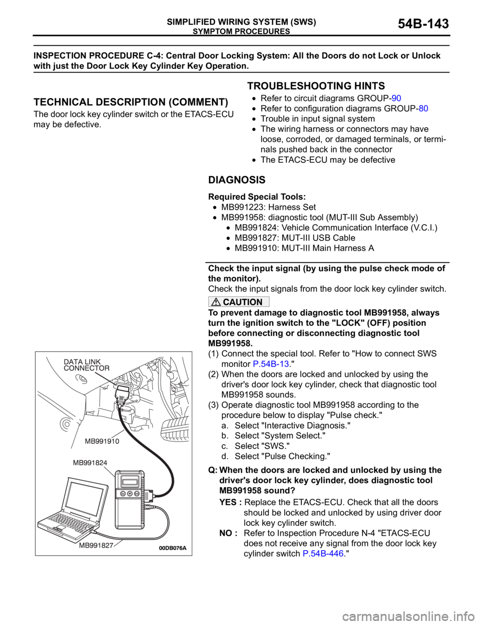
Required Special Tools:
MB991223: Harness Set
MB991958: diagnostic tool (MUT-III Sub Assembly)
MB991824: Vehicle Communication Interface (V.C.I.)
MB991827: MUT-III USB Cable
MB991910: MUT-III Main Harness A
Check the input signal (by using the pulse check mode of
the monitor).
Check the input signals from the door lock key cylinder switch.
To prevent damage to diagnostic tool MB991958, always
turn the ignition switch to the "LOCK" (OFF) position
before connecting or disconnecting diagnostic tool
MB991958.
(1) Connect the special tool. Refer to "How to connect SWS
monitor P.54B-13."
(2) When the doors are locked and unlocked by using the
driver's door lock key cylinder, check that diagnostic tool
MB991958 sounds.
(3) Operate diagnostic tool MB991958 according to the
procedure below to display "Pulse check."
a. Select "Interactive Diagnosis."
b. Select "System Select."
c. Select "SWS."
d. Select "Pulse Checking."
Q: When the doors are locked and unlocked by using the
driver's door lock key cylinder, does diagnostic tool
MB991958 sound?
YES : Replace the ETACS-ECU. Check that all the doors
should be locked and unlocked by using driver door
lock key cylinder switch.
NO : Refer to Inspection Procedure N-4 "ETACS-ECU
does not receive any signal from the door lock key
cylinder switch P.54B-446."
Page 144 of 1500

SYMPTOM PROCEDURES
SIMPLIFIED WIRING SYSTEM (SWS)54B-144
INSPECTION PROCEDURE C-5: Central Door Locking System: Forgotten Key Prevention Function
does not Work Normally.
NOTE: This troubleshooting procedure requires use
of diagnostic tool MB991958 and SWS monitor kit
MB991813. For details on how to use the SWS mon-
itor, refer to "How to connect SWS monitor
P.54B-13."
.
CIRCUIT OPERATION
The ETACS-ECU operates the forgotten key preven-
tion function according to the following switches:
Key reminder switch: OFF
Front door switch: ON
Front door lock actuator switch: being turned on
The ETACS-ECU operates the forgotten key preven-
tion function under the following conditions:
Ignition key: inserted into the ignition key cylinder
Front door: open
Front door lock: being locked
.
TECHNICAL DESCRIPTION (COMMENT)
If the function does not work normally, the input cir-
cuit system from the switches or the ETACS-ECU
may be defective (refer to "CIRCUIT OPERATION").
.
TROUBLESHOOTING HINTS
Refer to circuit diagrams GROUP-90
Refer to configuration diagrams GROUP-80
Trouble in input signal system
The wiring harness or connectors may have
loose, corroded, or damaged terminals, or termi-
nals pushed back in the connector
The ETACS-ECU may be defective
Page 148 of 1500

SYMPTOM PROCEDURES
SIMPLIFIED WIRING SYSTEM (SWS)54B-148
POWER WINDOWS
GENERAL DESCRIPTION CONCERNING THE POWER WINDOWSM1549021900244
The following ECUs affect the functions and control
of the power windows.Refer to circuit diagrams GROUP-90
Refer to configuration diagrams GROUP-80
FUNCTION CONTROL ECU
Power window main
switch functionRaises the driver’s power window Power window main switch
Lowers the driver’s power window Power window main switch
Lowers the driver’s power window by one-touch down
functionPower window main switch
Raises the passenger’s power window Power window main switch
Lowers the passenger’s power window Power window main switch
Power window sub
switch functionRaises the passenger’s power window Power window sub switch
Lowers the passenger’s power window Power window sub switch
Power window timer function ETACS-ECU
Page 151 of 1500
SYMPTOM PROCEDURES
SIMPLIFIED WIRING SYSTEM (SWS)54B-151
INSPECTION PROCEDURE D-1: Power Windows: Power windows do not work at all.
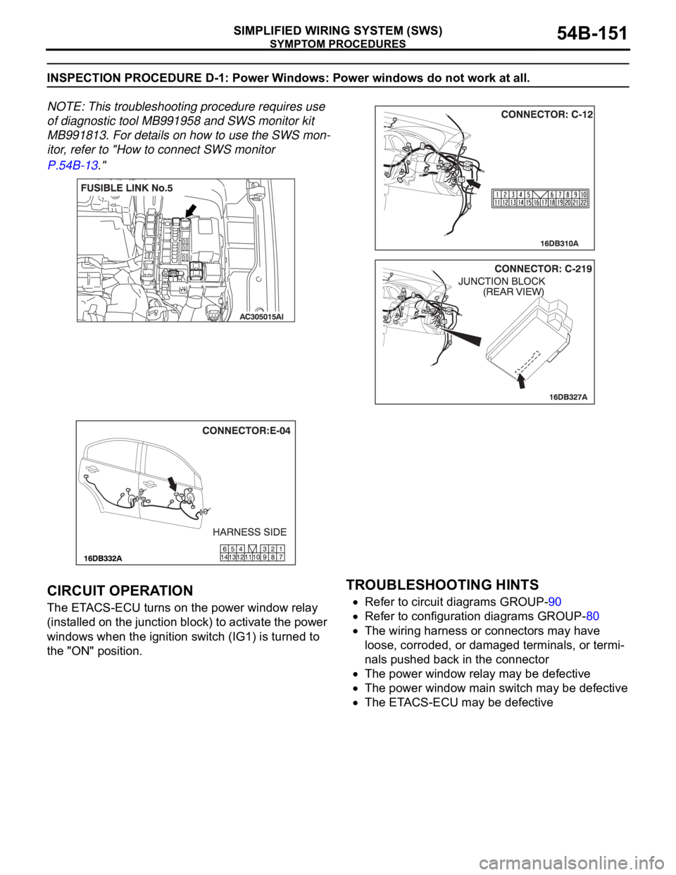
NOTE: This troubleshooting procedure requires use
of diagnostic tool MB991958 and SWS monitor kit
MB991813. For details on how to use the SWS mon-
itor, refer to "How to connect SWS monitor
P.54B-13."
.
CIRCUIT OPERATION
The ETACS-ECU turns on the power window relay
(installed on the junction block) to activate the power
windows when the ignition switch (IG1) is turned to
the "ON" position.
.
TROUBLESHOOTING HINTS
Refer to circuit diagrams GROUP-90
Refer to configuration diagrams GROUP-80
The wiring harness or connectors may have
loose, corroded, or damaged terminals, or termi-
nals pushed back in the connector
The power window relay may be defective
The power window main switch may be defective
The ETACS-ECU may be defective