steering MITSUBISHI 380 2005 Owner's Manual
[x] Cancel search | Manufacturer: MITSUBISHI, Model Year: 2005, Model line: 380, Model: MITSUBISHI 380 2005Pages: 1500, PDF Size: 47.87 MB
Page 1030 of 1500
CROSSMEMBER
POWER PLANT MOUNT32-13
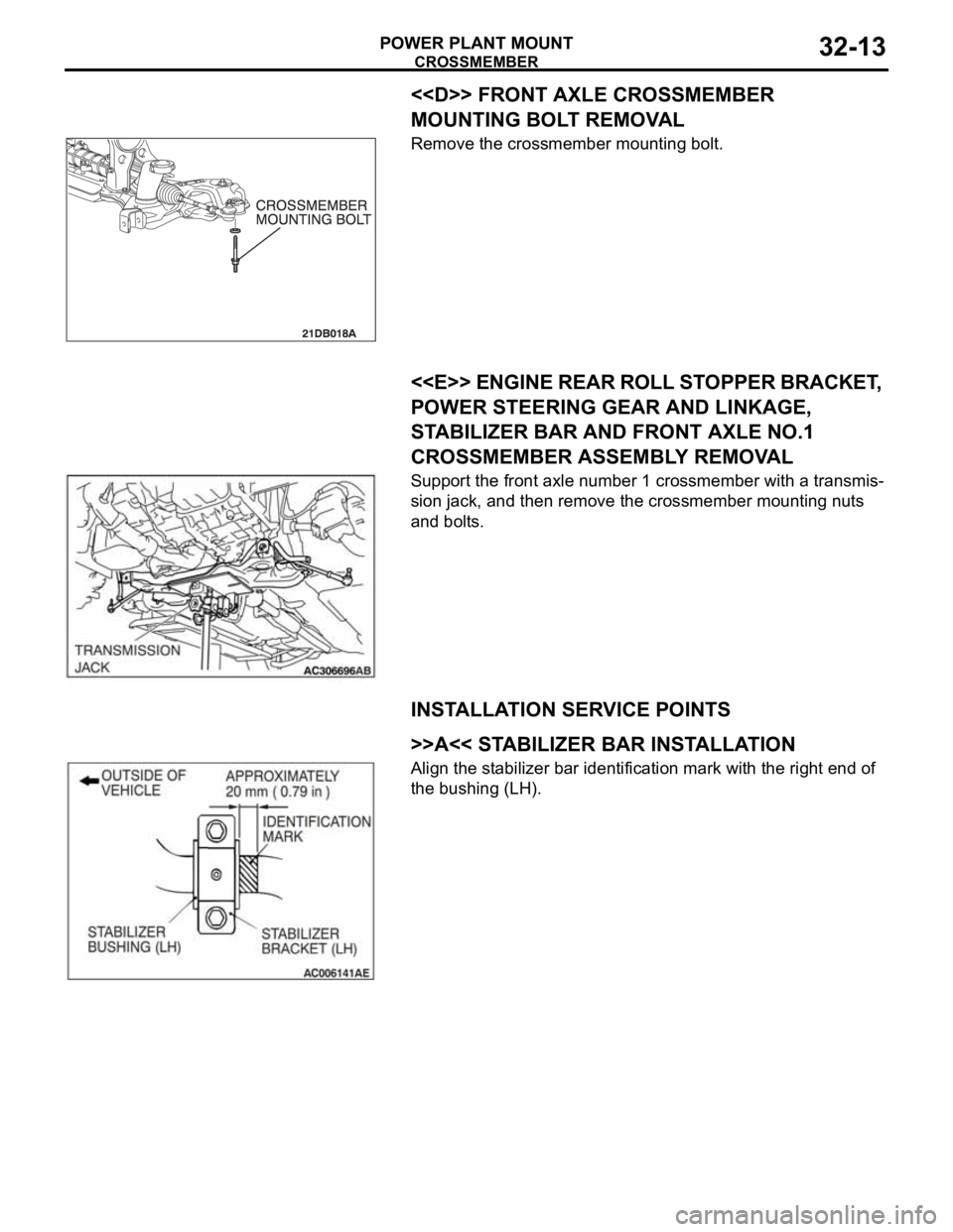
<
MOUNTING BOLT REMOVAL
Remove the crossmember mounting bolt.
.
<
POWER STEERING GEAR AND LINKAGE,
STABILIZER BAR AND FRONT AXLE NO.1
CROSSMEMBER ASSEMBLY REMOVAL
Support the front axle number 1 crossmember with a transmis-
sion jack, and then remove the crossmember mounting nuts
and bolts.
INSTALLATION SERVICE POINTS
.
>>A<< STABILIZER BAR INSTALLATION
Align the stabilizer bar identification mark with the right end of
the bushing (LH).
.
Page 1032 of 1500

SPECIFICATIONS
POWER PLANT MOUNT32-15
SPECIFICATIONS
FASTENER TIGHTENING SPECIFICATIONSM1321004100308
ITEM SPECIFICATION
Crossmember
Engine rear roll stopper bracket bolt 58
7 Nm
Front axle crossmember stay bolt and nut 83
12 Nm (61 9 ft-lb)
Front axle No.1 crossmember bolt and nut 180
20 Nm (133 15 ft-lb)
Lower arm assembly bolt 165
15 Nm (122 11 ft-lb)
Lower arm assembly nut (flange nut, self-locking) M14 165
15 Nm (122 11 ft-lb)
Lower arm ball joint clamp assembly nut 110
10 Nm
Power steering gear and linkage bolt 83
12 Nm (61 9 ft-lb)
Power steering gear bracket bolt M12 83
12 Nm (61 9 ft-lb)
Pressure hose clamp bolt and nut 12
2 Nm (102 22 in-lb)
Pressure hose nut 15
3 Nm (11 2 ft-lb)
Return tube clamp bolt and nut 12
2 Nm (102 22 in-lb)
Return tube nut 15
3 Nm (11 2 ft-lb)
Stabilizer bracket bolt 58
7 Nm (43 5 ft-lb)
Stabilizer link nut 48
7 Nm (36 5 ft-lb)
Steering column assembly bolt 18
2 Nm (13 2 ft-lb)
Steering gear and linkage protector bolt 12
2 Nm (102 22 in-lb)
Tie rod end nut 29
4 Nm (21 3 ft-lb)
Engine mounting
Engine mounting thru bolt M12 108
10 Nm (80 9 ft-lb)
Engine front mounting bracket bolt and nut M12 108
10 Nm (80 9 ft-lb)
Engine mounting stay bolt 36
6 Nm (27 4 ft-lb)
Engine roll stopper and centremember
Centremember bolt83
12 Nm (61 9 ft-lb)
Engine front roll stopper thru bolt and nut 69
10 Nm (61 9 ft-lb
Engine rear roll stopper thru bolt and nut 69
10 Nm (61 9 ft-lb
Transaxle case rear roll stopper bracket bolt 90
10 Nm (67 7 ft-lb)
Transaxle mounting
Transaxle mounting body side bracket nut (nut, flange) M12 83
12 Nm (61 9 ft-lb)
Transaxle mounting body side bracket nut (nut, self-locking) M1283
12 Nm (61 9 ft-lb)
Page 1167 of 1500
GENERAL DESCRIPTION
BASIC BRAKE SYSTEM35A-2
GENERAL DESCRIPTIONM1351000100440
The brake system has been designed to give greater
reliability and durability and to provide excellent brak-
ing performance.
FEATURES
.
Improved braking performance
1. An 8+9 inch tandem brake booster provides suffi-
cient braking force in sudden braking range.
2. 296mm front ventilated disc brakes provide sta-
ble braking force and improved braking feel.
3. 303mm rear ventillated disc brakes are used.
.
Improved stability
1. A 4-wheel anti-lock braking system (4ABS) pre-
vents slipping caused by the vehicle wheels lock-
ing up, in order to maintain a stable vehicle
posture and steering performance.
2. An electronic brake-force distribution (EBD)
makes it possible to maintain the maximum
amount of braking force even when the vehicle's
load is unevenly distributed. 3. Front- and rear-wheel X-type brake line layout
are used.
4. Ventilated discs brakes improve anti-fading per-
formance.
.
Improved serviceability
1. A diagnosis function for the ABS system makes
inspection easier.
2. An outer disc separated hub and rotor make
removal and installation easier.
3. The master cylinder reservoir is utilised for both
brake and clutch fluid on manual transmission
vehicles.
4. The master cylinder filter is coloured black for
improved viewing.
5. The ABS-ECU and hydraulic unit are integrated
to make them more compact and light weight.
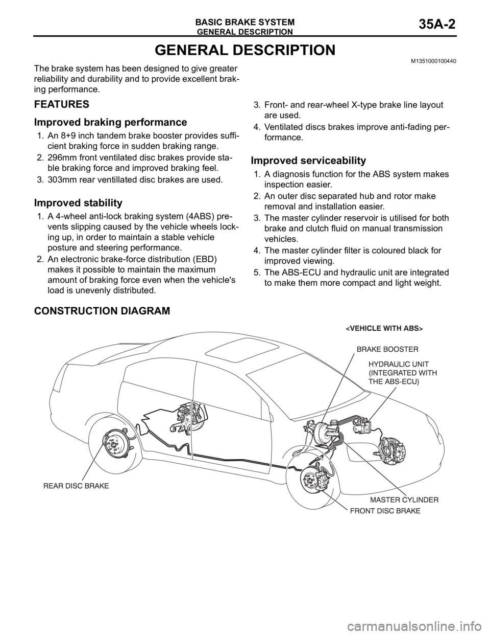
CONSTRUCTION DIAGRAM
Page 1223 of 1500
GENERAL00-2
MAINTENANCE SERVICE . . . . . . . .00-37
1. FUEL SYSTEM (TANK, PIPE LINE AND
CONNECTION, AND FUEL TANK FILLER
TUBE CAP) (CHECK FOR LEAKS) . . . . . . 00-37
2. FUEL HOSES (CHECK CONDITION) . . 00-37
3. AIR CLEANER FILTER (REPLACE). . . . 00-37
4. EVAPORATIVE EMISSION SYSTEM
(EXCEPT EVAPORATIVE EMISSION
CANISTER) (CHECK FOR CLOGGING) . . 00-37
5. SPARK PLUGS (REPLACE). . . . . . . . . . 00-38
7. TIMING BELT (REPLACE) . . . . . . . . . . . 00-38
8. DRIVE BELTS (FOR ALTERNATOR, POWER
STEERING PUMP AND AIR CONDITIONING)
(CHECK) . . . . . . . . . . . . . . . . . . . . . . . . . . . 00-39
9. EXHAUST SYSTEM (CONNECTIONS
PORTION OF MUFFLER, MUFFLER PIPES
AND CONVERTER HEAT SHIELDS) (CHECK
AND SERVICE AS REQUIRED) . . . . . . . . . 00-44
10. ENGINE OIL (CHANGE) . . . . . . . . . . . . 00-4411. ENGINE OIL FILTER (REPLACE) . . . . 00-44
12. TRANSMISSION FLUID . . . . . . . . . . . . 00-45
13. ENGINE COOLANT (CHANGE) . . . . . . 00-47
14. COOLANT HOSES (RADIATOR HOSE,
HEATER HOSE) (INSPECT). . . . . . . . . . . . 00-49
15. DISC BRAKE PADS, ROTORS
(INSPECT FOR WEAR) . . . . . . . . . . . . . . . 00-49
16. BRAKE HOSES (CHECK FOR
DETERIORATION OR LEAKS) . . . . . . . . . . 00-49
17. BALL JOINT AND STEERING LINKAGE
SEALS (INSPECT FOR GREASE LEAKS
AND DAMAGE) . . . . . . . . . . . . . . . . . . . . . . 00-50
18. DRIVE SHAFT BOOTS (INSPECT FOR
GREASE LEAKS AND DAMAGE) . . . . . . . . 00-50
19. SUSPENSION SYSTEM (INSPECT FOR
LOOSENESS AND DAMAGE) . . . . . . . . . . 00-51
20. SRS AIR BAG (INSPECT FOR SRS
SYSTEM). . . . . . . . . . . . . . . . . . . . . . . . . . . 00-51
21. TYRES (ROTATE). . . . . . . . . . . . . . . . . 00-58
Page 1243 of 1500
PRECAUTIONS BEFORE SERVICE
GENERAL00-22
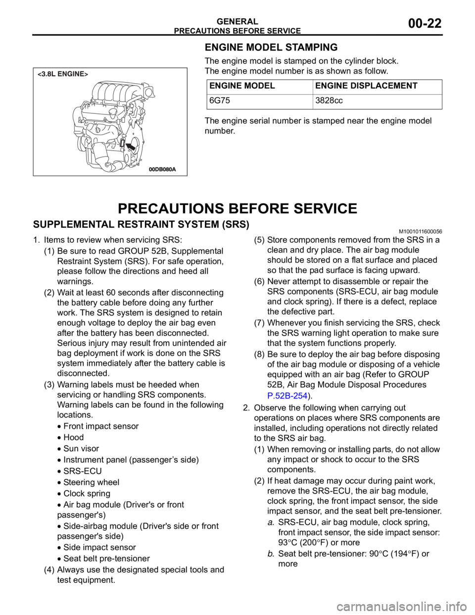
ENGINE MODEL STAMPING
The engine model is stamped on the cylinder block.
The engine model number is as shown as follow.
The engine serial number is stamped near the engine model
number.
PRECAUTIONS BEFORE SERVICE
SUPPLEMENTAL RESTRAINT SYSTEM (SRS)M1001011600056
1. Items to review when servicing SRS:
(1) Be sure to read GROUP 52B, Supplemental
Restraint System (SRS). For safe operation,
please follow the directions and heed all
warnings.
(2) Wait at least 60 seconds after disconnecting
the battery cable before doing any further
work. The SRS system is designed to retain
enough voltage to deploy the air bag even
after the battery has been disconnected.
Serious injury may result from unintended air
bag deployment if work is done on the SRS
system immediately after the battery cable is
disconnected.
(3) Warning labels must be heeded when
servicing or handling SRS components.
Warning labels can be found in the following
locations.
Front impact sensor
Hood
Sun visor
Instrument panel (passenger ’s side)
SRS-ECU
Steering wheel
Clock spring
Air bag module (Driver's or front
passenger's)
Side-airbag module (Driver's side or front
passenger's side)
Side impact sensor
Seat belt pre-tensioner
(4) Always use the designated special tools and
test equipment.(5) Store components removed from the SRS in a
clean and dry place. The air bag module
should be stored on a flat surface and placed
so that the pad surface is facing upward.
(6) Never attempt to disassemble or repair the
SRS components (SRS-ECU, air bag module
and clock spring). If there is a defect, replace
the defective part.
(7) Whenever you finish servicing the SRS, check
the SRS warning light operation to make sure
that the system functions properly.
(8) Be sure to deploy the air bag before disposing
of the air bag module or disposing of a vehicle
equipped with an air bag (Refer to GROUP
52B, Air Bag Module Disposal Procedures
P.52B-254).
2. Observe the following when carrying out
operations on places where SRS components are
installed, including operations not directly related
to the SRS air bag.
(1) When removing or installing parts, do not allow
any impact or shock to occur to the SRS
components.
(2) If heat damage may occur during paint work,
remove the SRS-ECU, the air bag module,
clock spring, the front impact sensor, the side
impact sensor, and the seat belt pre-tensioner.
a.SRS-ECU, air bag module, clock spring,
front impact sensor, the side impact sensor:
93
C (200F) or more
b.Seat belt pre-tensioner: 90
C (194F) or
more ENGINE MODEL ENGINE DISPLACEMENT
6G75 3828cc
Page 1245 of 1500
PRECAUTIONS BEFORE SERVICE
GENERAL00-24
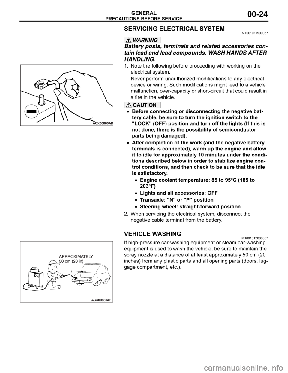
SERVICING ELECTRICAL SYSTEMM1001011900057
Battery posts, terminals and related accessories con-
tain lead and lead compounds. WASH HANDS AFTER
HANDLING.
1. Note the following before proceeding with working on the
electrical system.
Never perform unauthorized modifications to any electrical
device or wiring. Such modifications might lead to a vehicle
malfunction, over-capacity or short-circuit that could result in
a fire in the vehicle.
Before connecting or disconnecting the negative bat-
tery cable, be sure to turn the ignition switch to the
"LOCK" (OFF) position and turn off the lights (If this is
not done, there is the possibility of semiconductor
parts being damaged).
After completion of the work (and the negative battery
terminals is connected), warm up the engine and allow
it to idle for approximately 10 minutes under the condi-
tions described below in order to stabilize engine con-
trol conditions, and then check to be sure that the idle
is satisfactory.
Engine coolant temperature: 85 to 95C (185 to
203
F)
Lights and all accessories: OFF
Transaxle: "N" or "P" position
Steering wheel: straight-forward position
2. When servicing the electrical system, disconnect the
negative cable terminal from the battery.
VEHICLE WASHINGM1001012000057
If high-pressure car-washing equipment or steam car-washing
equipment is used to wash the vehicle, be sure to maintain the
spray nozzle at a distance of at least approximately 50 cm (20
inches) from any plastic parts and all opening parts (doors, lug-
gage compartment, etc.).
Page 1248 of 1500
TOWING AND HOISTING
GENERAL00-27
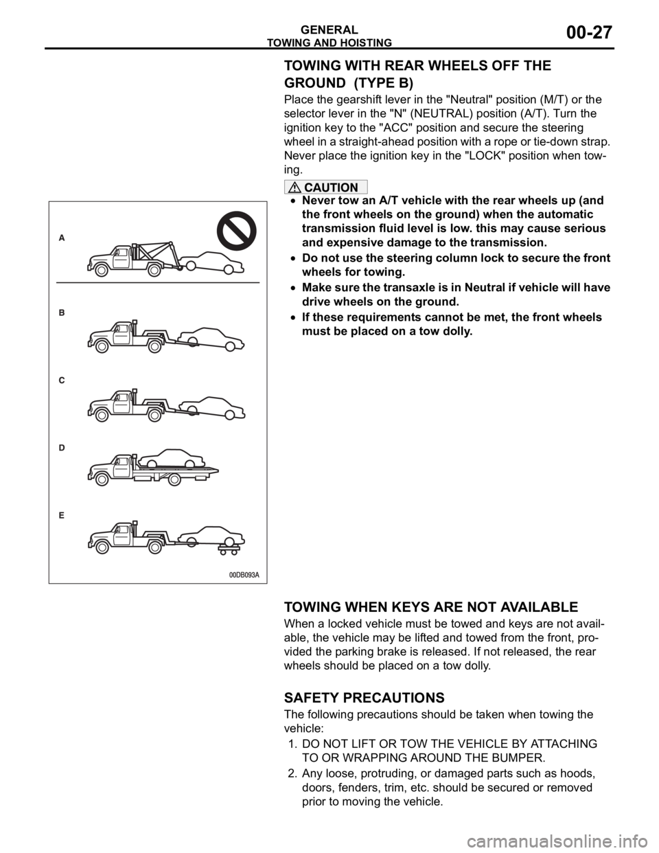
TOWING WITH REAR WHEELS OFF THE
GROUND (TYPE B)
Place the gearshift lever in the "Neutral" position (M/T) or the
selector lever in the "N" (NEUTRAL) position (A/T). Turn the
ignition key to the "ACC" position and secure the steering
wheel in a straight-ahead position with a rope or tie-down strap.
Never place the ignition key in the "LOCK" position when tow-
ing.
Never tow an A/T vehicle with the rear wheels up (and
the front wheels on the ground) when the automatic
transmission fluid level is low. this may cause serious
and expensive damage to the transmission.
Do not use the steering column lock to secure the front
wheels for towing.
Make sure the transaxle is in Neutral if vehicle will have
drive wheels on the ground.
If these requirements cannot be met, the front wheels
must be placed on a tow dolly.
.
TOWING WHEN KEYS ARE NOT AVAILABLE
When a locked vehicle must be towed and keys are not avail-
able, the vehicle may be lifted and towed from the front, pro-
vided the parking brake is released. If not released, the rear
wheels should be placed on a tow dolly.
.
SAFETY PRECAUTIONS
The following precautions should be taken when towing the
vehicle:
1. DO NOT LIFT OR TOW THE VEHICLE BY ATTACHING
TO OR WRAPPING AROUND THE BUMPER.
2. Any loose, protruding, or damaged parts such as hoods,
doors, fenders, trim, etc. should be secured or removed
prior to moving the vehicle.
Page 1256 of 1500

RECOMMENDED LUBRICANTS AND LUBRICANT CAPACITIES TABLE
GENERAL00-35
RECOMMENDED LUBRICANTS AND LUBRICANT
CAPACITIES TABLE
M1001001300504
RECOMMENDED LUBRICANTS
LUBRICANT CAPACITY TABLE
<3.8L ENGINE>LUBRICANT SPECIFICATION
Engine oil Engine oils conforming to ACEA A1, A2 or A3 and
AP1 SG or higher
AutomaticTransmission fluid Genuine Mitsubishi Motors ATF-SP III
Manual Transmission fluid Genuine Mitsubishi Motors MTF
Power steering fluid ATF DEXRON III or DEXRON II
Brakes fluid Conforming to DOT 3 or DOT 4
Engine coolant Genuine Mitsubishi Motors coolant
Refrigerant (air conditioning) HFC-134a
DESCRIPTION SPECIFICATION
Engine oil (Litres) Oil pan (excluding oil filter) 4.0
Oil filter 0.3
Engine coolant (Litres) 8.7
Automatic Transmission fluid (Litres) 8.4
Manual Transmission fluid (Litres) 2.8
Power steering fluid (Litres) 1.2
Fuel tank (Litres) 67.0
Washer fluid (Litres) 5.0
Refrigerant (air conditioning) (grams) 435g - 475g
Page 1260 of 1500
MAINTENANCE SERVICE
GENERAL00-39
7. DRIVE BELTS (FOR ALTERNATOR, POWER
STEERING PUMP AND AIR CONDITIONING)
(CHECK)
M1001008700031
ALTERNATOR DRIVE BELT TENSION CHECK
<3.8L ENGINE>
.
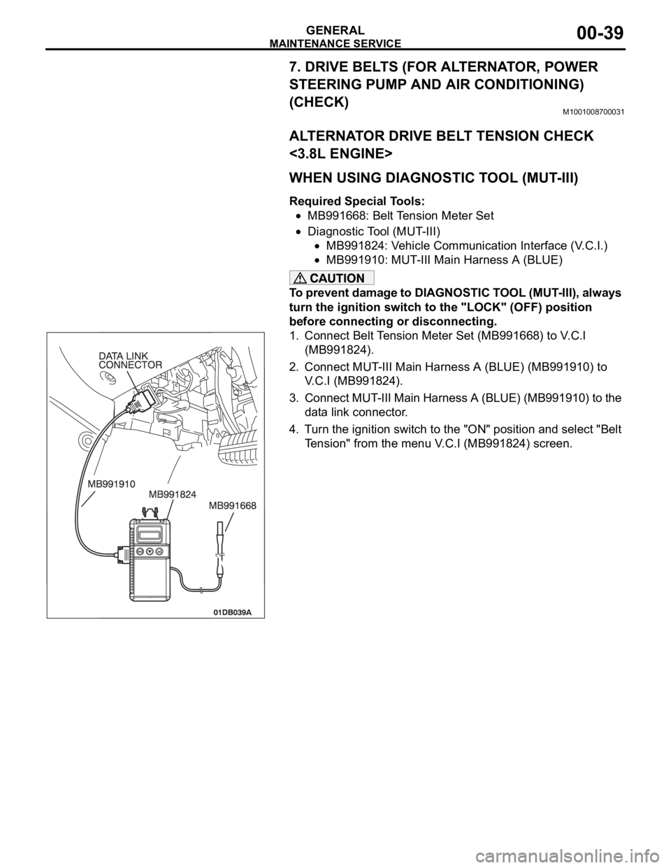
WHEN USING DIAGNOSTIC TOOL (MUT-III)
Required Special Tools:
MB991668: Belt Tension Meter Set
Diagnostic Tool (MUT-III)
MB991824: Vehicle Communication Interface (V.C.I.)
MB991910: MUT-III Main Harness A (BLUE)
To prevent damage to DIAGNOSTIC TOOL (MUT-III), always
turn the ignition switch to the "LOCK" (OFF) position
before connecting or disconnecting.
1. Connect Belt Tension Meter Set (MB991668) to V.C.I
(MB991824).
2. Connect MUT-III Main Harness A (BLUE) (MB991910) to
V.C.I (MB991824).
3. Connect MUT-III Main Harness A (BLUE) (MB991910) to the
data link connector.
4. Turn the ignition switch to the "ON" position and select "Belt
Tension" from the menu V.C.I (MB991824) screen.
Page 1263 of 1500

MAINTENANCE SERVICE
GENERAL00-42
ALTERNATOR DRIVE BELT TENSION
ADJUSTMENT
.1. Loosen the tensioner pulley fixing nut.
2. With the tensioner pulley fixing nut temporarily tightened to
15
5 Nm (11 4 ft-lb), set the belt tension or defection
amount to the standard value using the adjusting bolt.
Standard value:
3. Tighten the tension pulley fixing nut.
Tightening torque: 49
10 Nm (36 7 ft-lb)
POWER STEERING DRIVE BELT TENSION
CHECK
.
WHEN USING DIAGNOSTIC TOOL (MUT-III)
Required Special Tools:
MB991668: Belt Tension Meter Set
Diagnostic Tool (MUT-III)
MB991824: Vehicle Communication Interface (V.C.I.)
MB991910: MUT-III Main Harness A (BLUE)
Gently tap the middle of the belt between the pulleys (the loca-
tion indicated by the arrow) with your finger as shown in the
illustration, and check that the vibration frequency of the belt is
within the standard value.
NOTE: Refer to P.00-39 for details on the method of measuring
the vibration frequency using the scan tool.
Standard value:
.
ITEMS DURING
ADJUSTMENTDURING
REPLACEMENT
Vibration
frequency Hz150
163 180 202
Tension N (lb) 539
637
(121
143)785
981
(176
221)
Deflection
(Reference value)
mm (in)8.9
10.1
(0.35
0.40)6.2
7.5
(0.24
0.30)
ITEM WHEN
CHECKEDDURING
ADJUSTME
NTDURING
REPLACEM
ENT
Vibration
frequency Hz124
160 134 151 160 189