steering MITSUBISHI 380 2005 Owner's Guide
[x] Cancel search | Manufacturer: MITSUBISHI, Model Year: 2005, Model line: 380, Model: MITSUBISHI 380 2005Pages: 1500, PDF Size: 47.87 MB
Page 1271 of 1500
MAINTENANCE SERVICE
GENERAL00-50
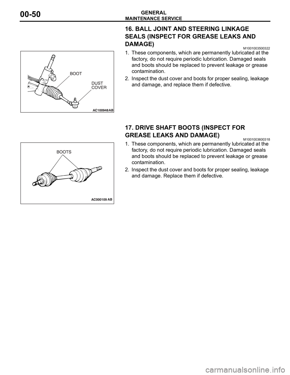
16. BALL JOINT AND STEERING LINKAGE
SEALS (INSPECT FOR GREASE LEAKS AND
DAMAGE)
M1001003500322
1. These components, which are permanently lubricated at the
factory, do not require periodic lubrication. Damaged seals
and boots should be replaced to prevent leakage or grease
contamination.
2. Inspect the dust cover and boots for proper sealing, leakage
and damage, and replace them if defective.
17. DRIVE SHAFT BOOTS (INSPECT FOR
GREASE LEAKS AND DAMAGE)
M1001003600318
1. These components, which are permanently lubricated at the
factory, do not require periodic lubrication. Damaged seals
and boots should be replaced to prevent leakage or grease
contamination.
2. Inspect the dust cover and boots for proper sealing, leakage
and damage. Replace them if defective.
Page 1274 of 1500
MAINTENANCE SERVICE
GENERAL00-53
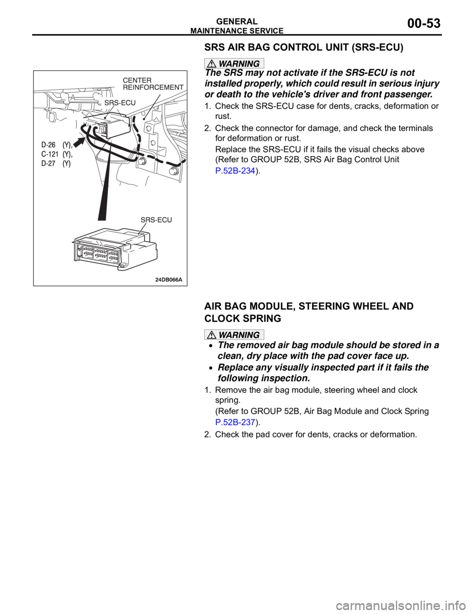
SRS AIR BAG CONTROL UNIT (SRS-ECU)
The SRS may not activate if the SRS-ECU is not
installed properly, which could result in serious injury
or death to the vehicle's driver and front passenger.
1. Check the SRS-ECU case for dents, cracks, deformation or
rust.
2. Check the connector for damage, and check the terminals
for deformation or rust.
Replace the SRS-ECU if it fails the visual checks above
(Refer to GROUP 52B, SRS Air Bag Control Unit
P.52B-234).
AIR BAG MODULE, STEERING WHEEL AND
CLOCK SPRING
The removed air bag module should be stored in a
clean, dry place with the pad cover face up.
Replace any visually inspected part if it fails the
following inspection.
1. Remove the air bag module, steering wheel and clock
spring.
(Refer to GROUP 52B, Air Bag Module and Clock Spring
P.52B-237).
2. Check the pad cover for dents, cracks or deformation.
Page 1275 of 1500
MAINTENANCE SERVICE
GENERAL00-54
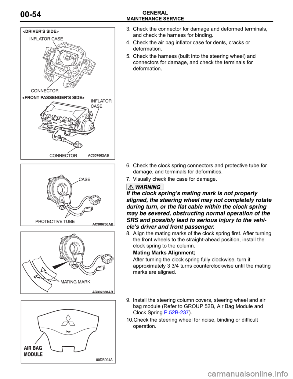
3. Check the connector for damage and deformed terminals,
and check the harness for binding.
4. Check the air bag inflator case for dents, cracks or
deformation.
5. Check the harness (built into the steering wheel) and
connectors for damage, and check the terminals for
deformation.
6. Check the clock spring connectors and protective tube for
damage, and terminals for deformities.
7. Visually check the case for damage.
If the clock spring's mating mark is not properly
aligned, the steering wheel may not completely rotate
during turn, or the flat cable within the clock spring
may be severed, obstructing normal operation of the
SRS and possibly lead to serious injury to the vehi-
cle's driver and front passenger.
8. Align the mating marks of the clock spring first. After turning
the front wheels to the straight-ahead position, install the
clock spring to the column.
Mating Marks Alignment;
After turning the clock spring fully clockwise, turn it
approximately 3 3/4 turns counterclockwise until the mating
marks are aligned.
9. Install the steering column covers, steering wheel and air
bag module (Refer to GROUP 52B, Air Bag Module and
Clock Spring P.52B-237).
10.Check the steering wheel for noise, binding or difficult
operation.
Page 1276 of 1500
MAINTENANCE SERVICE
GENERAL00-55
The SRS may not activate if any of the above compo-
nents are not installed properly, which could result in
serious injury or death to the vehicle's driver and
front passenger.
11.Check the steering wheel for excessive free play.
Replace any part if it fails visual inspection (Refer to
GROUP 52B, Air Bag Module and Clock Spring P.52B-237).
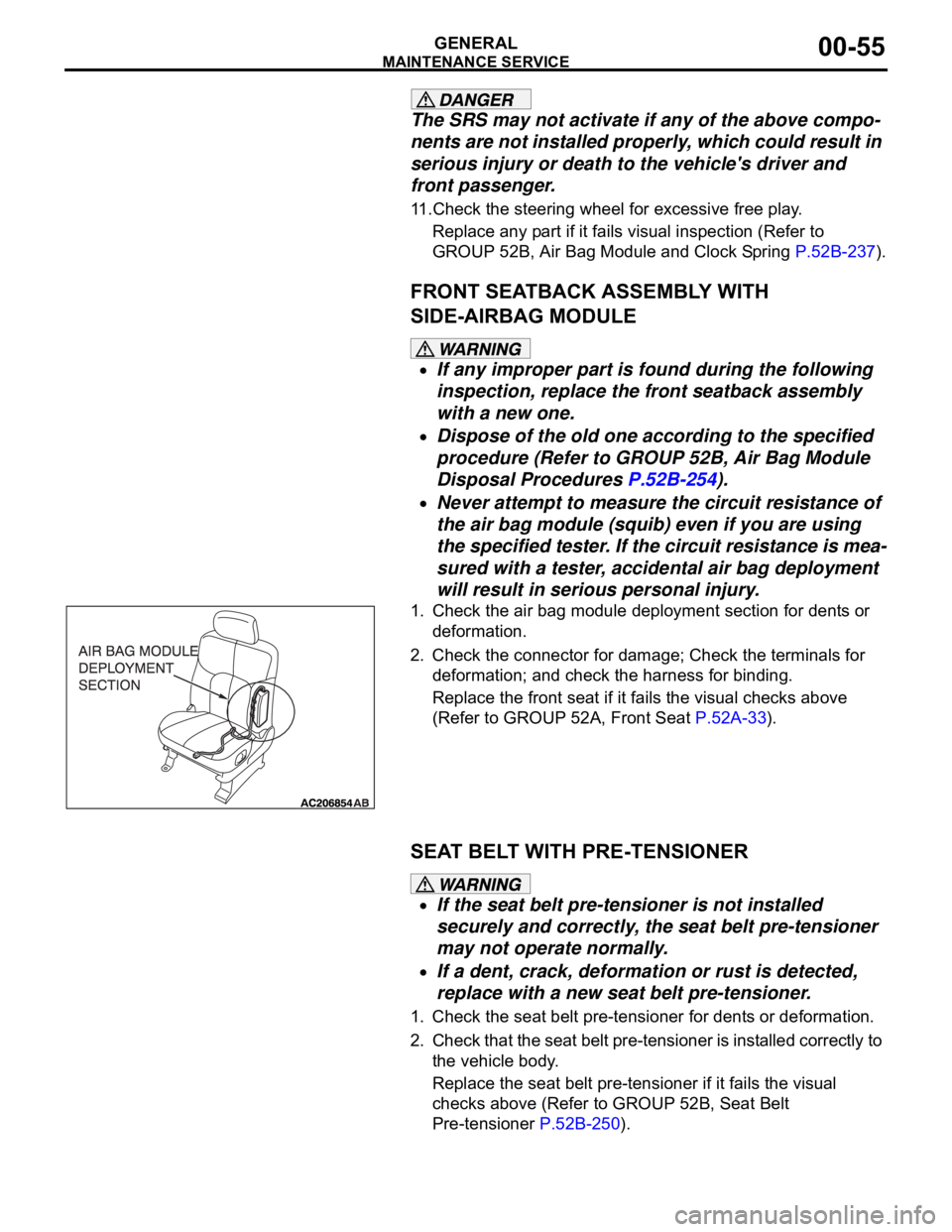
FRONT SEATBACK ASSEMBLY WITH
SIDE-AIRBAG MODULE
If any improper part is found during the following
inspection, replace the front seatback assembly
with a new one.
Dispose of the old one according to the specified
procedure (Refer to GROUP 52B, Air Bag Module
Disposal Procedures P.52B-254).
Never attempt to measure the circuit resistance of
the air bag module (squib) even if you are using
the specified tester. If the circuit resistance is mea-
sured with a tester, accidental air bag deployment
will result in serious personal injury.
1. Check the air bag module deployment section for dents or
deformation.
2. Check the connector for damage; Check the terminals for
deformation; and check the harness for binding.
Replace the front seat if it fails the visual checks above
(Refer to GROUP 52A, Front Seat P.52A-33).
SEAT BELT WITH PRE-TENSIONER
If the seat belt pre-tensioner is not installed
securely and correctly, the seat belt pre-tensioner
may not operate normally.
If a dent, crack, deformation or rust is detected,
replace with a new seat belt pre-tensioner.
1. Check the seat belt pre-tensioner for dents or deformation.
2. Check that the seat belt pre-tensioner is installed correctly to
the vehicle body.
Replace the seat belt pre-tensioner if it fails the visual
checks above (Refer to GROUP 52B, Seat Belt
Pre-tensioner P.52B-250).
Page 1406 of 1500
AUTO-CRUISE CONTROL
ENGINE AND EMISSION CONTROL17-75
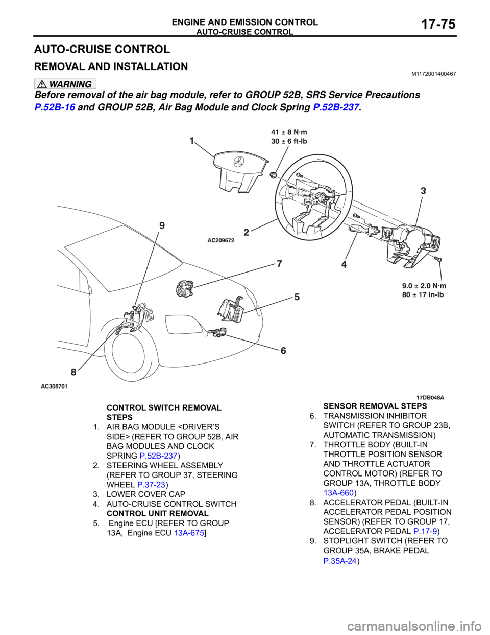
AUTO-CRUISE CONTROL
REMOVAL AND INSTALLATIONM1172001400467
Before removal of the air bag module, refer to GROUP 52B, SRS Service Precautions
P.52B-16 and GROUP 52B, Air Bag Module and Clock Spring P.52B-237.
CONTROL SWITCH REMOVAL
STEPS
1. AIR BAG MODULE
BAG MODULES AND CLOCK
SPRING P.52B-237)
2. STEERING WHEEL ASSEMBLY
(REFER TO GROUP 37, STEERING
WHEEL P.37-23)
3. LOWER COVER CAP
4. AUTO-CRUISE CONTROL SWITCH
CONTROL UNIT REMOVAL
5. Engine ECU [REFER TO GROUP
13A, Engine ECU 13A-675] SENSOR REMOVAL STEPS
6. TRANSMISSION INHIBITOR
SWITCH (REFER TO GROUP 23B,
AUTOMATIC TRANSMISSION)
7. THROTTLE BODY (BUILT-IN
THROTTLE POSITION SENSOR
AND THROTTLE ACTUATOR
CONTROL MOTOR) (REFER TO
GROUP 13A, THROTTLE BODY
13A-660)
8. ACCELERATOR PEDAL (BUILT-IN
ACCELERATOR PEDAL POSITION
SENSOR) (REFER TO GROUP 17,
ACCELERATOR PEDAL P.17-9)
9. STOPLIGHT SWITCH (REFER TO
GROUP 35A, BRAKE PEDAL
P.35A-24)
Page 1416 of 1500

SPECIFICATIONS
ENGINE AND EMISSION CONTROL17-85
SPECIFICATIONS
FASTENER TIGHTENING SPECIFICATIONSM1173006400324
SERVICE SPECIFICATIONSM1173000300545
ITEM SPECIFICATION
Auto-cruise control system
Lower cover cap bolt 9.0
2.0 Nm (80 17 in-lb)
Steering wheel assembly nut 41
8 Nm (30 6 ft-lb)
Engine control system
Accelerator pedal assembly nut 13
2 Nm ( 111 22 in-lb)
ITEMSSTANDARD VALUE
Engine control system
Curb idle speed r/min 3.8L Engine 680
100
Emission control system
Purge flow cm
3/s (SCFH) [at 80 95C (176 205F) with sudden revving]20 (2.5)
Evaporative emission purge solenoid coil resistance [at 20
C)] 16
Page 1421 of 1500
SPECIAL TOOLS
FRONT AXLE26-4
STEP 5. Retest the system.
Q: Is the abnormal noise eliminated?
YES : The procedure is complete.
NO : Repeat from Step 1.
INSPECTION PROCEDURE 2: Noise Due to Excessive Play of Wheel in Turning Direction
DIAGNOSIS
STEP 1. Check for play in the inner shaft and side
gear serration, the drive shaft and side gear
serration, or the drive shaft and front hub
serration.
Q: Is the play found?
YES :
Replace the part. Then go to Step 2.
NO : The procedure is complete.
STEP 2. Retest the system.
Q: Is the abnormal noise eliminated?
YES :
The procedure is complete.
NO : Repeat from Step 1.
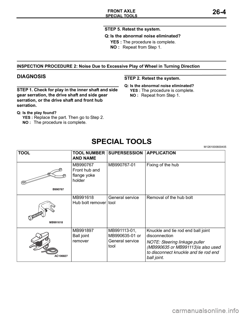
SPECIAL TOOLSM1261000600405
TOOL TOOL NUMBER
AND NAMESUPERSESSION APPLICATION
MB990767
Front hub and
flange yoke
holderMB990767-01 Fixing of the hub
MB991618
Hub bolt removerGeneral service
toolRemoval of the hub bolt
MB991897
Ball joint
removerMB991113-01,
MB990635-01 or
General service
tool Knuckle and tie rod end ball joint
disconnection
NOTE: Steering linkage puller
(MB990635 or MB991113)is also used
to disconnect knuckle and tie rod end
ball joint.
Page 1451 of 1500
SPECIAL TOOLS
REAR AXLE27-4
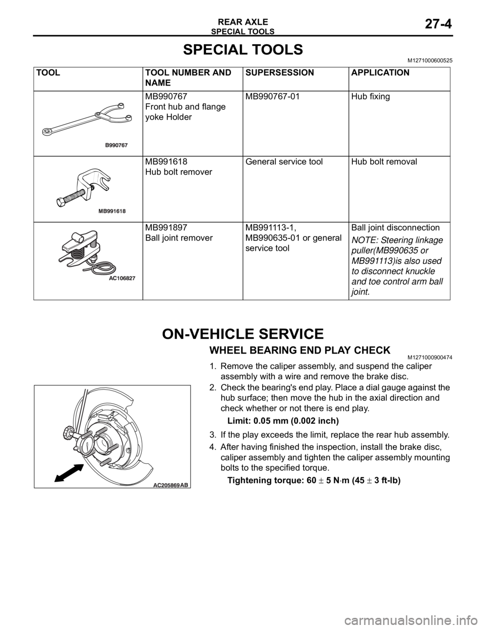
SPECIAL TOOLSM1271000600525
ON-VEHICLE SERVICE
WHEEL BEARING END PLAY CHECKM1271000900474
1. Remove the caliper assembly, and suspend the caliper
assembly with a wire and remove the brake disc.
2. Check the bearing's end play. Place a dial gauge against the
hub surface; then move the hub in the axial direction and
check whether or not there is end play.
Limit: 0.05 mm (0.002 inch)
3. If the play exceeds the limit, replace the rear hub assembly.
4. After having finished the inspection, install the brake disc,
caliper assembly and tighten the caliper assembly mounting
bolts to the specified torque.
Tightening torque: 60
5 Nm (45 3 ft-lb) TOOL TOOL NUMBER AND
NAMESUPERSESSION APPLICATION
MB990767
Front hub and flange
yoke HolderMB990767-01 Hub fixing
MB991618
Hub bolt removerGeneral service tool Hub bolt removal
MB991897
Ball joint removerMB991113-1,
MB990635-01 or general
service toolBall joint disconnection
NOTE: Steering linkage
puller(MB990635 or
MB991113)is also used
to disconnect knuckle
and toe control arm ball
joint.