Battery MITSUBISHI 380 2005 Owner's Guide
[x] Cancel search | Manufacturer: MITSUBISHI, Model Year: 2005, Model line: 380, Model: MITSUBISHI 380 2005Pages: 1500, PDF Size: 47.87 MB
Page 210 of 1500
SYMPTOM PROCEDURES
SIMPLIFIED WIRING SYSTEM (SWS)54B-210
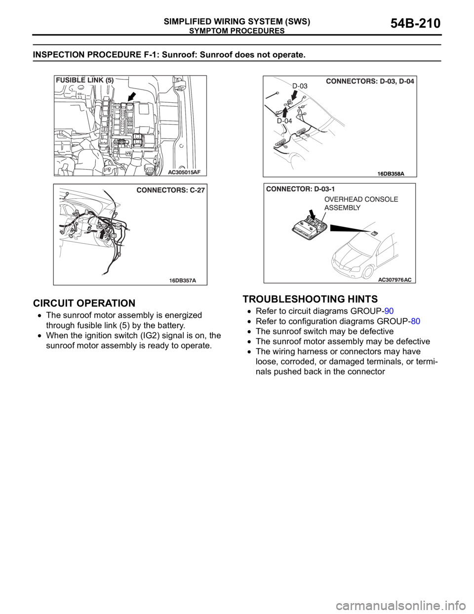
INSPECTION PROCEDURE F-1: Sunroof: Sunroof does not operate.
.
CIRCUIT OPERATION
The sunroof motor assembly is energized
through fusible link (5) by the battery.
When the ignition switch (IG2) signal is on, the
sunroof motor assembly is ready to operate.
.
TROUBLESHOOTING HINTS
Refer to circuit diagrams GROUP-90
Refer to configuration diagrams GROUP-80
The sunroof switch may be defective
The sunroof motor assembly may be defective
The wiring harness or connectors may have
loose, corroded, or damaged terminals, or termi-
nals pushed back in the connector
Page 211 of 1500
SYMPTOM PROCEDURES
SIMPLIFIED WIRING SYSTEM (SWS)54B-211
DIAGNOSIS
Required Special Tool:
MB991223: Test Harness Set
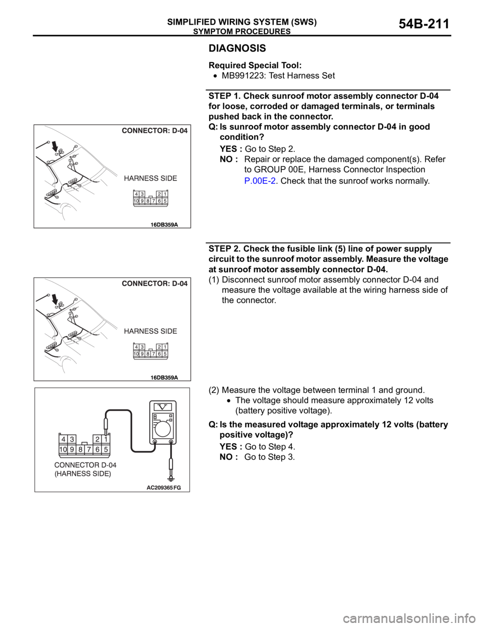
STEP 1. Check sunroof motor assembly connector D-04
for loose, corroded or damaged terminals, or terminals
pushed back in the connector.
Q: Is sunroof motor assembly connector D-04 in good
condition?
YES : Go to Step 2.
NO : Repair or replace the damaged component(s). Refer
to GROUP 00E, Harness Connector Inspection
P.00E-2. Check that the sunroof works normally.
STEP 2. Check the fusible link (5) line of power supply
circuit to the sunroof motor assembly. Measure the voltage
at sunroof motor assembly connector D-04.
(1) Disconnect sunroof motor assembly connector D-04 and
measure the voltage available at the wiring harness side of
the connector.
(2) Measure the voltage between terminal 1 and ground.
The voltage should measure approximately 12 volts
(battery positive voltage).
Q: Is the measured voltage approximately 12 volts (battery
positive voltage)?
YES : Go to Step 4.
NO : Go to Step 3.
Page 213 of 1500
SYMPTOM PROCEDURES
SIMPLIFIED WIRING SYSTEM (SWS)54B-213
STEP 4. Check the ignition switch (IG2) circuit to the
sunroof motor assembly. Measure the voltage at sunroof
motor assembly connector D-04.
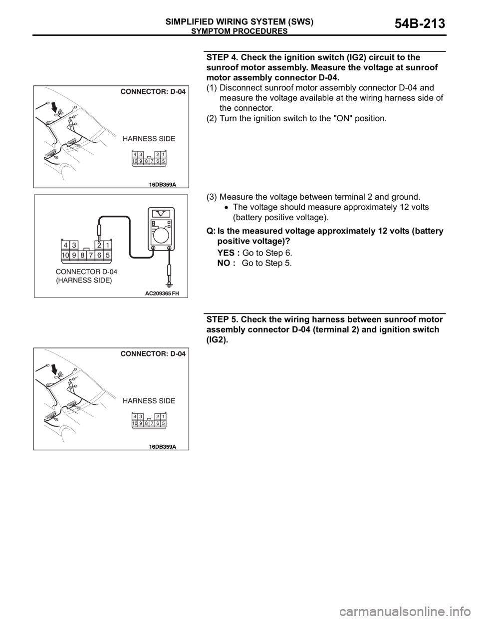
(1) Disconnect sunroof motor assembly connector D-04 and
measure the voltage available at the wiring harness side of
the connector.
(2) Turn the ignition switch to the "ON" position.
(3) Measure the voltage between terminal 2 and ground.
The voltage should measure approximately 12 volts
(battery positive voltage).
Q: Is the measured voltage approximately 12 volts (battery
positive voltage)?
YES : Go to Step 6.
NO : Go to Step 5.
STEP 5. Check the wiring harness between sunroof motor
assembly connector D-04 (terminal 2) and ignition switch
(IG2).
Page 230 of 1500
SYMPTOM PROCEDURES
SIMPLIFIED WIRING SYSTEM (SWS)54B-230
STEP 4. Check the windshield wiper motor.
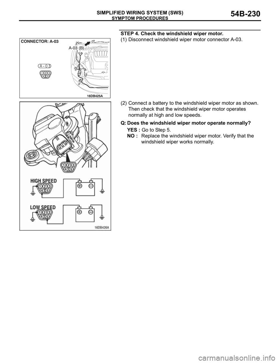
(1) Disconnect windshield wiper motor connector A-03.
(2) Connect a battery to the windshield wiper motor as shown.
Then check that the windshield wiper motor operates
normally at high and low speeds.
Q: Does the windshield wiper motor operate normally?
YES : Go to Step 5.
NO : Replace the windshield wiper motor. Verify that the
windshield wiper works normally.
Page 232 of 1500
SYMPTOM PROCEDURES
SIMPLIFIED WIRING SYSTEM (SWS)54B-232
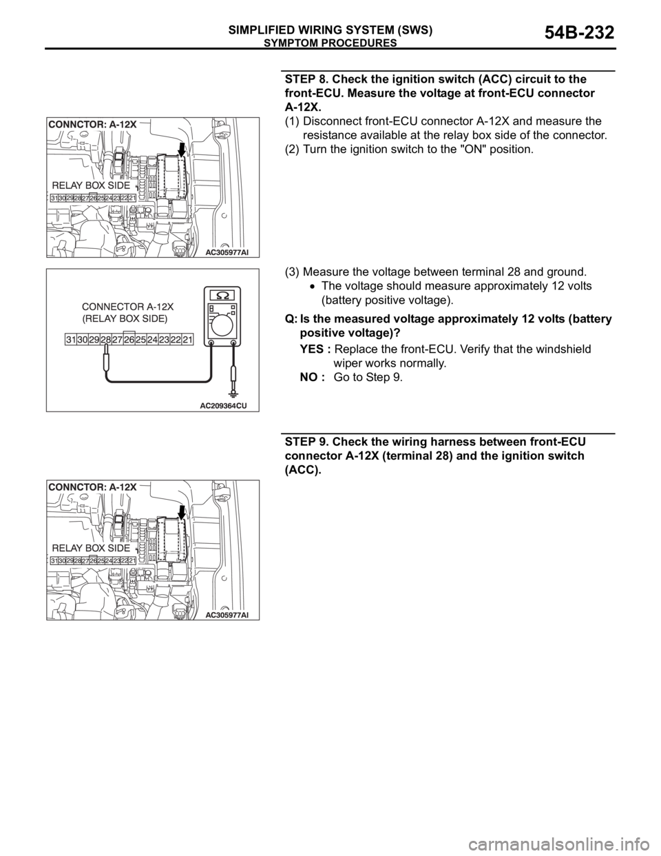
STEP 8. Check the ignition switch (ACC) circuit to the
front-ECU. Measure the voltage at front-ECU connector
A-12X.
(1) Disconnect front-ECU connector A-12X and measure the
resistance available at the relay box side of the connector.
(2) Turn the ignition switch to the "ON" position.
(3) Measure the voltage between terminal 28 and ground.
The voltage should measure approximately 12 volts
(battery positive voltage).
Q: Is the measured voltage approximately 12 volts (battery
positive voltage)?
YES : Replace the front-ECU. Verify that the windshield
wiper works normally.
NO : Go to Step 9.
STEP 9. Check the wiring harness between front-ECU
connector A-12X (terminal 28) and the ignition switch
(ACC).
Page 238 of 1500
SYMPTOM PROCEDURES
SIMPLIFIED WIRING SYSTEM (SWS)54B-238
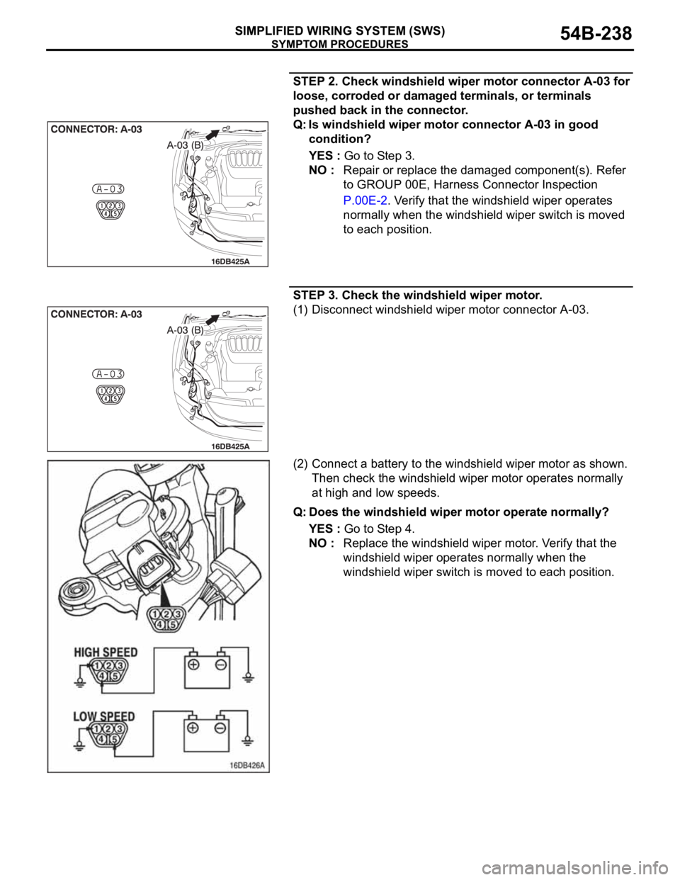
STEP 2. Check windshield wiper motor connector A-03 for
loose, corroded or damaged terminals, or terminals
pushed back in the connector.
Q: Is windshield wiper motor connector A-03 in good
condition?
YES : Go to Step 3.
NO : Repair or replace the damaged component(s). Refer
to GROUP 00E, Harness Connector Inspection
P.00E-2. Verify that the windshield wiper operates
normally when the windshield wiper switch is moved
to each position.
STEP 3. Check the windshield wiper motor.
(1) Disconnect windshield wiper motor connector A-03.
(2) Connect a battery to the windshield wiper motor as shown.
Then check the windshield wiper motor operates normally
at high and low speeds.
Q: Does the windshield wiper motor operate normally?
YES : Go to Step 4.
NO : Replace the windshield wiper motor. Verify that the
windshield wiper operates normally when the
windshield wiper switch is moved to each position.
Page 242 of 1500
SYMPTOM PROCEDURES
SIMPLIFIED WIRING SYSTEM (SWS)54B-242
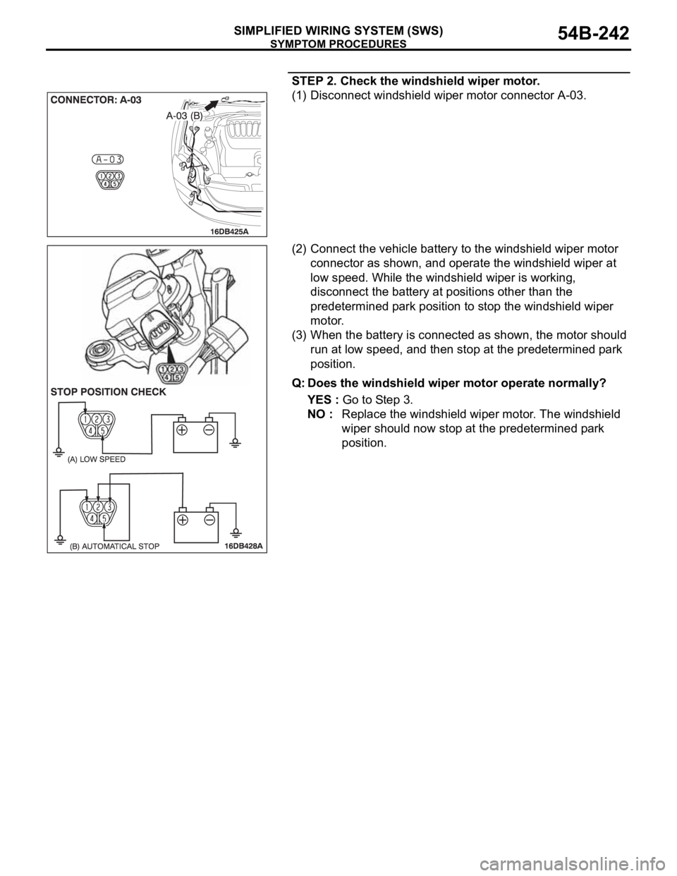
STEP 2. Check the windshield wiper motor.
(1) Disconnect windshield wiper motor connector A-03.
(2) Connect the vehicle battery to the windshield wiper motor
connector as shown, and operate the windshield wiper at
low speed. While the windshield wiper is working,
disconnect the battery at positions other than the
predetermined park position to stop the windshield wiper
motor.
(3) When the battery is connected as shown, the motor should
run at low speed, and then stop at the predetermined park
position.
Q: Does the windshield wiper motor operate normally?
YES : Go to Step 3.
NO : Replace the windshield wiper motor. The windshield
wiper should now stop at the predetermined park
position.
Page 243 of 1500
SYMPTOM PROCEDURES
SIMPLIFIED WIRING SYSTEM (SWS)54B-243
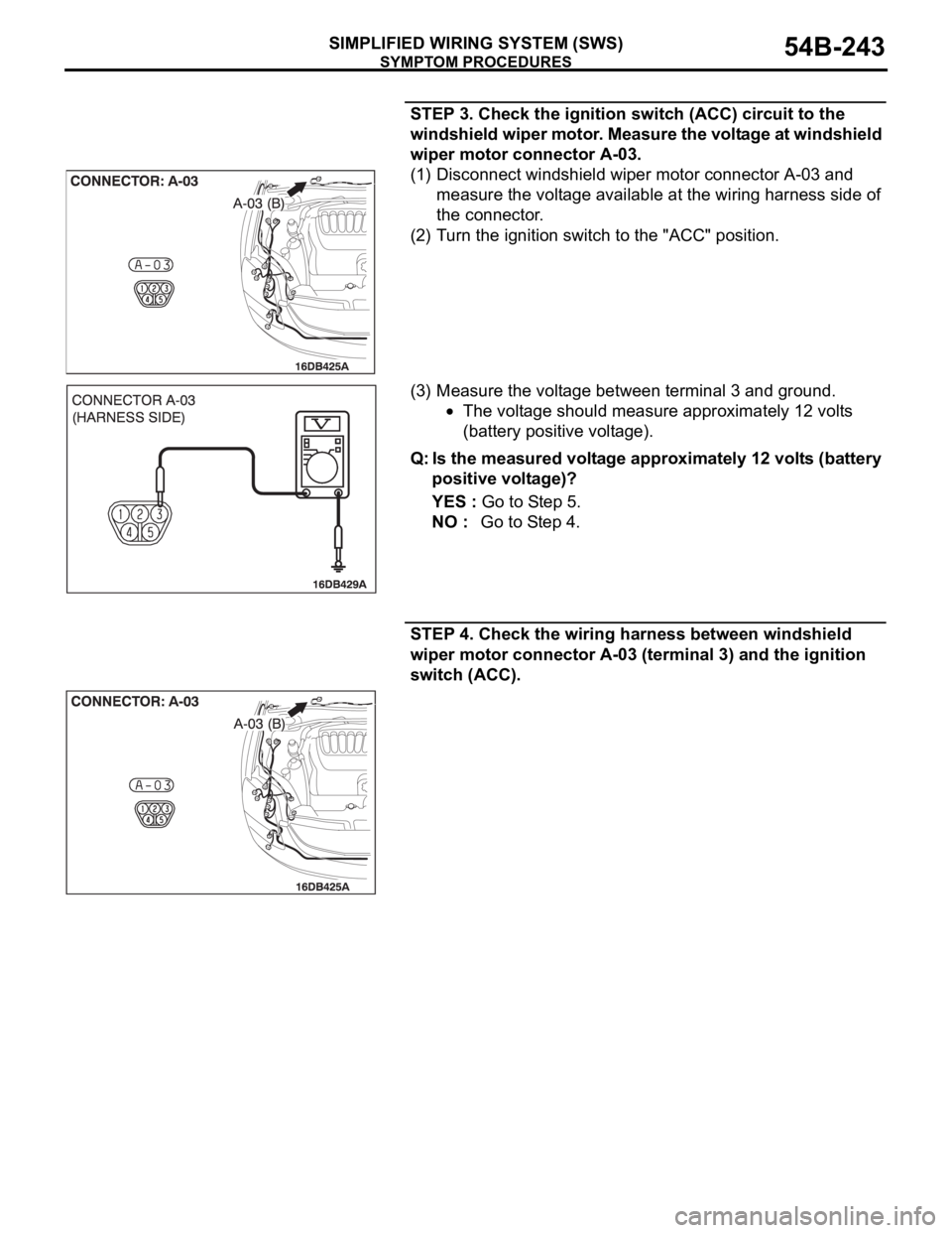
STEP 3. Check the ignition switch (ACC) circuit to the
windshield wiper motor. Measure the voltage at windshield
wiper motor connector A-03.
(1) Disconnect windshield wiper motor connector A-03 and
measure the voltage available at the wiring harness side of
the connector.
(2) Turn the ignition switch to the "ACC" position.
(3) Measure the voltage between terminal 3 and ground.
The voltage should measure approximately 12 volts
(battery positive voltage).
Q: Is the measured voltage approximately 12 volts (battery
positive voltage)?
YES : Go to Step 5.
NO : Go to Step 4.
STEP 4. Check the wiring harness between windshield
wiper motor connector A-03 (terminal 3) and the ignition
switch (ACC).
Page 254 of 1500
SYMPTOM PROCEDURES
SIMPLIFIED WIRING SYSTEM (SWS)54B-254
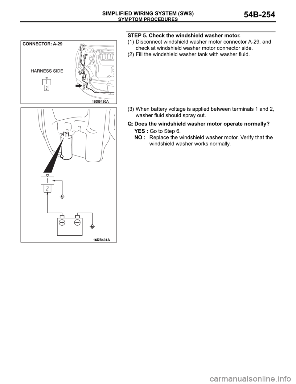
STEP 5. Check the windshield washer motor.
(1) Disconnect windshield washer motor connector A-29, and
check at windshield washer motor connector side.
(2) Fill the windshield washer tank with washer fluid.
(3) When battery voltage is applied between terminals 1 and 2,
washer fluid should spray out.
Q: Does the windshield washer motor operate normally?
YES : Go to Step 6.
NO : Replace the windshield washer motor. Verify that the
windshield washer works normally.
Page 259 of 1500
SYMPTOM PROCEDURES
SIMPLIFIED WIRING SYSTEM (SWS)54B-259
Headlamp automatic-shutdown function
Even if the lighting switch (taillamps switch or headlamp switch)
is ON, the headlamps (including the taillamps) will automati-
cally go off in the following conditions to prevent the battery
from discharging as a result of forgetting to turn off lamps.
If the ignition key is turned from "ON" to "LOCK" (OFF) or
"ACC" position with the lighting switch turned ON, and this
state continues for three minutes, the headlamps will automati-
cally be turned off. If the driver's seat door is opened during
these three minutes, the headlamps will go off one second
later.
NOTE: The headlamp automatic-shutoff function can be cus-
tomized on vehicles equipped with a multi center display (mid-
dle grade type). Refer to P.54B-486.
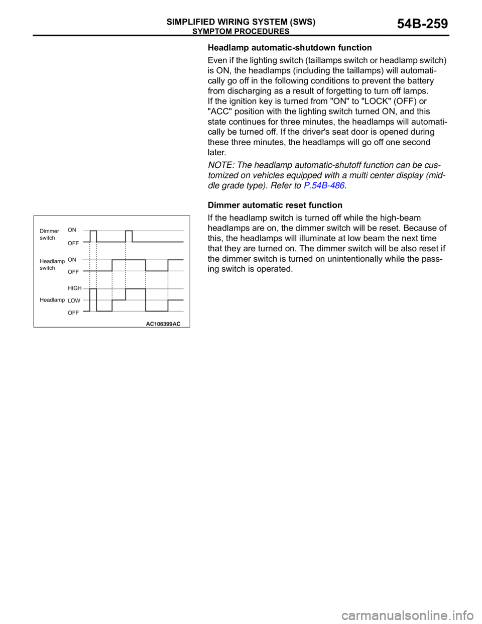
Dimmer automatic reset function
If the headlamp switch is turned off while the high-beam
headlamps are on, the dimmer switch will be reset. Because of
this, the headlamps will illuminate at low beam the next time
that they are turned on. The dimmer switch will be also reset if
the dimmer switch is turned on unintentionally while the pass-
ing switch is operated.