Battery MITSUBISHI 380 2005 Manual PDF
[x] Cancel search | Manufacturer: MITSUBISHI, Model Year: 2005, Model line: 380, Model: MITSUBISHI 380 2005Pages: 1500, PDF Size: 47.87 MB
Page 734 of 1500
AUTO A/C DIAGNOSIS
HEATER, AIR CONDITIONING AND VENTILATION55-33
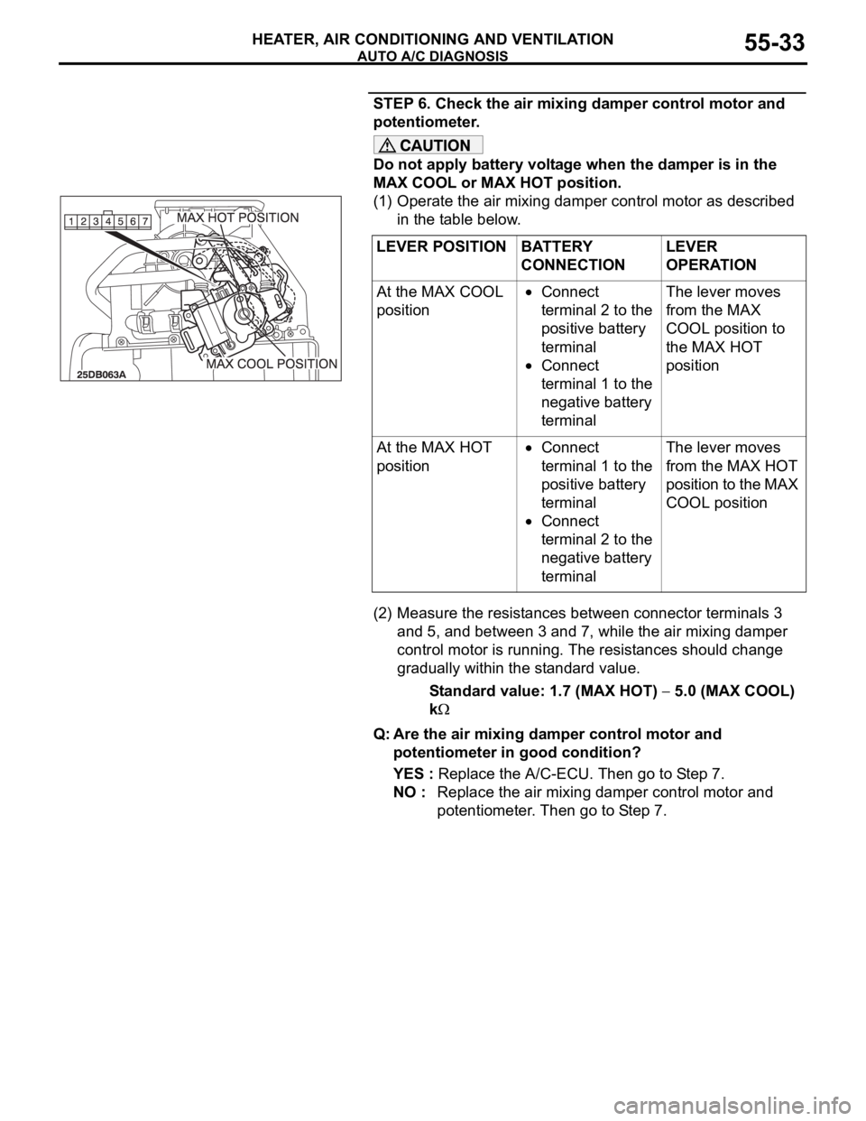
STEP 6. Check the air mixing damper control motor and
potentiometer.
Do not apply battery voltage when the damper is in the
MAX COOL or MAX HOT position.
(1) Operate the air mixing damper control motor as described
in the table below.
(2) Measure the resistances between connector terminals 3
and 5, and between 3 and 7, while the air mixing damper
control motor is running. The resistances should change
gradually within the standard value.
Standard value: 1.7 (MAX HOT)
5.0 (MAX COOL)
k
Q: Are the air mixing damper control motor and
potentiometer in good condition?
YES : Replace the A/C-ECU. Then go to Step 7.
NO : Replace the air mixing damper control motor and
potentiometer. Then go to Step 7. LEVER POSITION BATTERY
CONNECTIONLEVER
OPERATION
At the MAX COOL
position
Connect
terminal 2 to the
positive battery
terminal
Connect
terminal 1 to the
negative battery
terminalThe lever moves
from the MAX
COOL position to
the MAX HOT
position
At the MAX HOT
position
Connect
terminal 1 to the
positive battery
terminal
Connect
terminal 2 to the
negative battery
terminalThe lever moves
from the MAX HOT
position to the MAX
COOL position
Page 740 of 1500

AUTO A/C DIAGNOSIS
HEATER, AIR CONDITIONING AND VENTILATION55-39
STEP 6. Check the air mixing damper control motor and
potentiometer.
Do not apply battery voltage when the damper is in the
MAX COOL or MAX HOT position.
Check the air mix damper control motor by the following proce-
dures.
Q: Are the air mixing damper control motor and
potentiometer in good condition?
YES : Replace the A/C-ECU. Then go to Step 7.
NO : Replace the air mixing damper control motor and
potentiometer. Then go to Step 7. LEVER POSITION BATTERY
CONNECTIONLEVER
OPERATION
At the MAX COOL
position
Connect
terminal 2 to the
positive battery
terminal
Connect
terminal 1 to the
negative battery
terminalThe lever moves
from the MAX
COOL position to
the MAX HOT
position
At the MAX HOT
position
Connect
terminal 1 to the
positive battery
terminal
Connect
terminal 2 to the
negative battery
terminalThe lever moves
from the MAX HOT
position to the MAX
COOL position
Page 747 of 1500
AUTO A/C DIAGNOSIS
HEATER, AIR CONDITIONING AND VENTILATION55-46
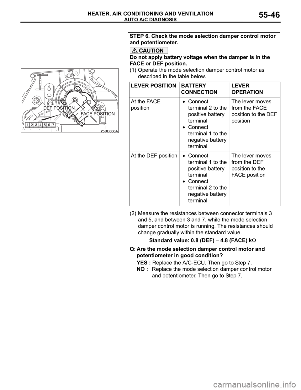
STEP 6. Check the mode selection damper control motor
and potentiometer.
Do not apply battery voltage when the damper is in the
FACE or DEF position.
(1) Operate the mode selection damper control motor as
described in the table below.
(2) Measure the resistances between connector terminals 3
and 5, and between 3 and 7, while the mode selection
damper control motor is running. The resistances should
change gradually within the standard value.
Standard value: 0.8 (DEF)
4.8 (FACE) k
Q: Are the mode selection damper control motor and
potentiometer in good condition?
YES : Replace the A/C-ECU. Then go to Step 7.
NO : Replace the mode selection damper control motor
and potentiometer. Then go to Step 7. LEVER POSITION BATTERY
CONNECTIONLEVER
OPERATION
At the FACE
position
Connect
terminal 2 to the
positive battery
terminal
Connect
terminal 1 to the
negative battery
terminalThe lever moves
from the FACE
position to the DEF
position
At the DEF position
Connect
terminal 1 to the
positive battery
terminal
Connect
terminal 2 to the
negative battery
terminalThe lever moves
from the DEF
position to the
FACE position
Page 753 of 1500
AUTO A/C DIAGNOSIS
HEATER, AIR CONDITIONING AND VENTILATION55-52
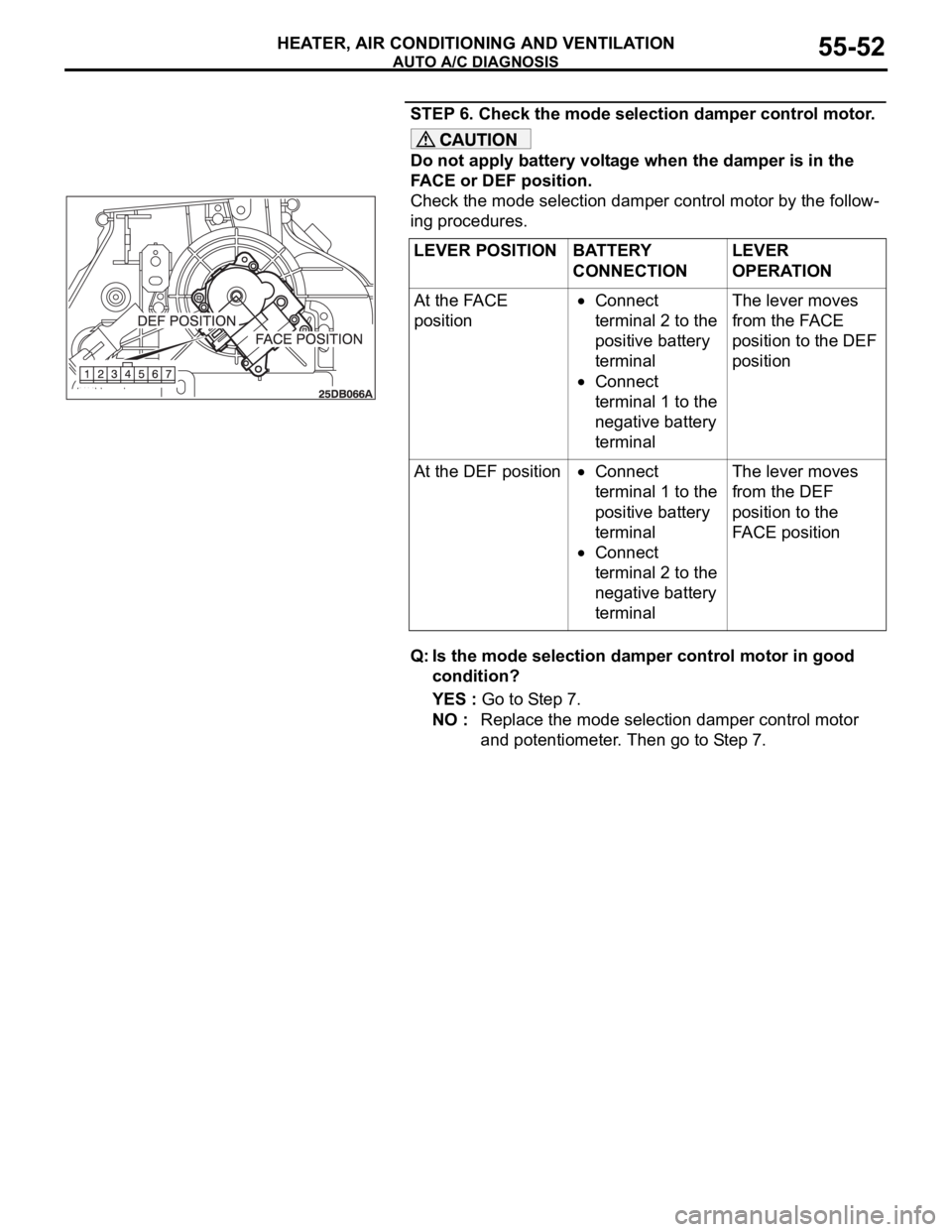
STEP 6. Check the mode selection damper control motor.
Do not apply battery voltage when the damper is in the
FACE or DEF position.
Check the mode selection damper control motor by the follow-
ing procedures.
Q: Is the mode selection damper control motor in good
condition?
YES : Go to Step 7.
NO : Replace the mode selection damper control motor
and potentiometer. Then go to Step 7. LEVER POSITION BATTERY
CONNECTIONLEVER
OPERATION
At the FACE
position
Connect
terminal 2 to the
positive battery
terminal
Connect
terminal 1 to the
negative battery
terminalThe lever moves
from the FACE
position to the DEF
position
At the DEF position
Connect
terminal 1 to the
positive battery
terminal
Connect
terminal 2 to the
negative battery
terminalThe lever moves
from the DEF
position to the
FACE position
Page 772 of 1500
AUTO A/C DIAGNOSIS
HEATER, AIR CONDITIONING AND VENTILATION55-71
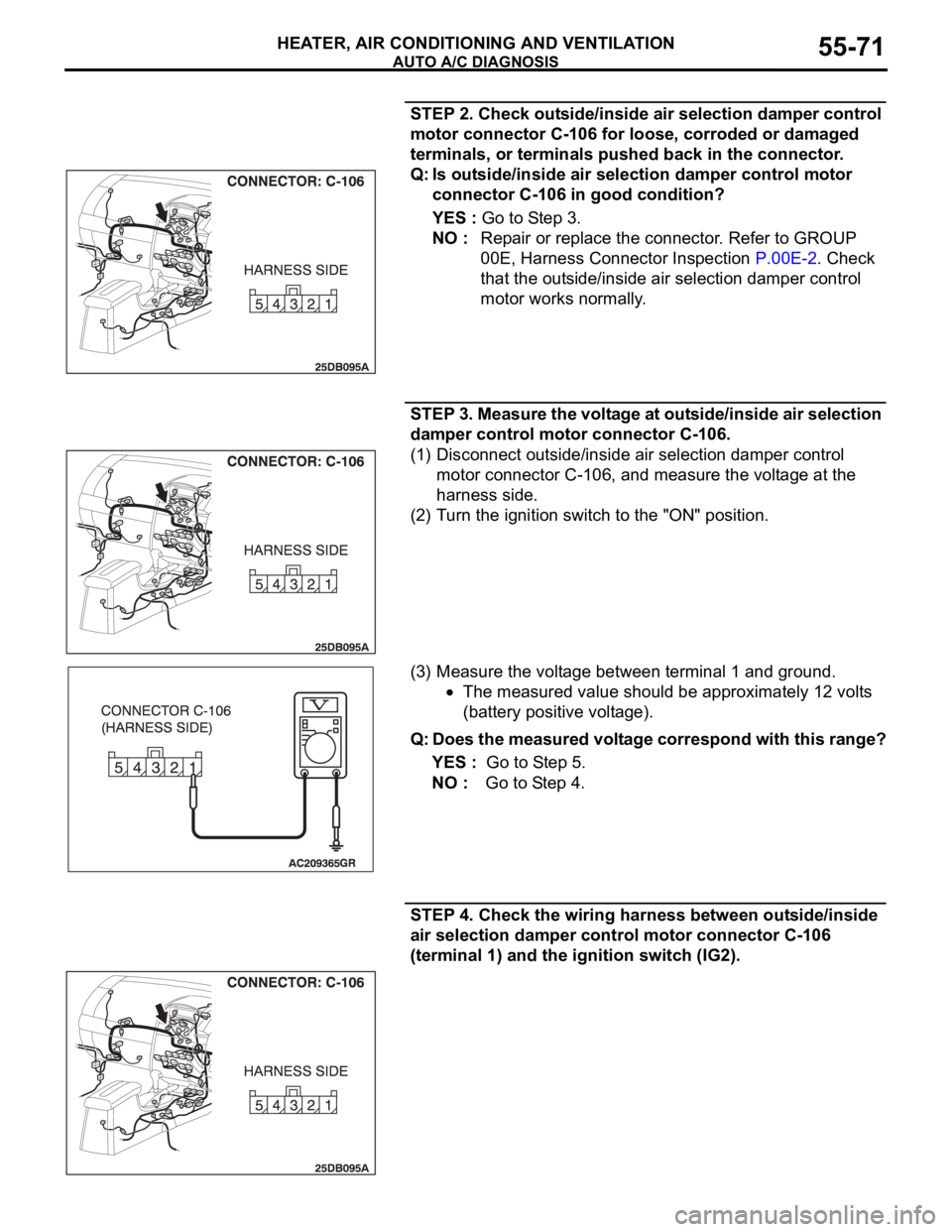
STEP 2. Check outside/inside air selection damper control
motor connector C-106 for loose, corroded or damaged
terminals, or terminals pushed back in the connector.
Q: Is outside/inside air selection damper control motor
connector C-106 in good condition?
YES : Go to Step 3.
NO : Repair or replace the connector. Refer to GROUP
00E, Harness Connector Inspection P.00E-2. Check
that the outside/inside air selection damper control
motor works normally.
STEP 3. Measure the voltage at outside/inside air selection
damper control motor connector C-106.
(1) Disconnect outside/inside air selection damper control
motor connector C-106, and measure the voltage at the
harness side.
(2) Turn the ignition switch to the "ON" position.
(3) Measure the voltage between terminal 1 and ground.
The measured value should be approximately 12 volts
(battery positive voltage).
Q: Does the measured voltage correspond with this range?
YES : Go to Step 5.
NO : Go to Step 4.
STEP 4. Check the wiring harness between outside/inside
air selection damper control motor connector C-106
(terminal 1) and the ignition switch (IG2).
Page 774 of 1500
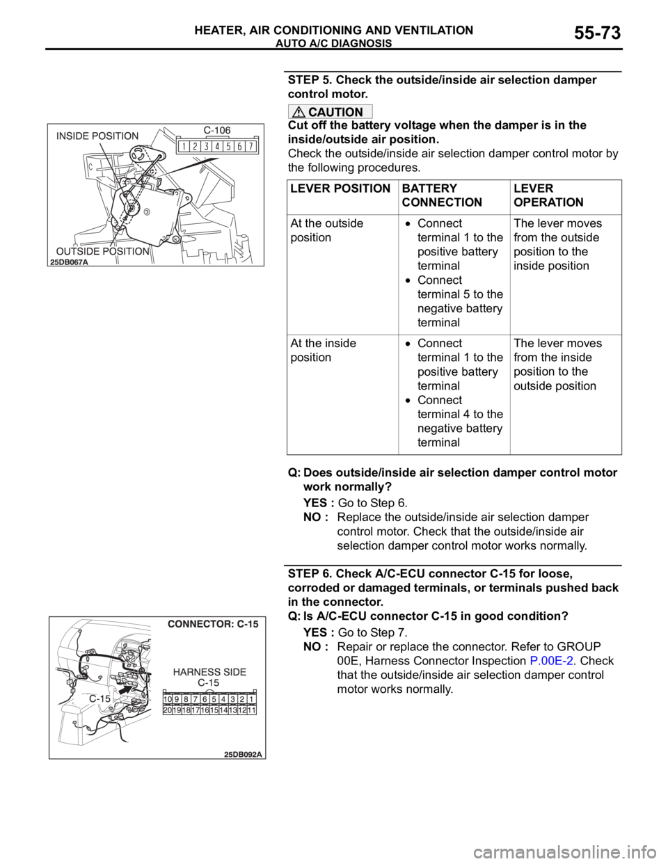
AUTO A/C DIAGNOSIS
HEATER, AIR CONDITIONING AND VENTILATION55-73
STEP 5. Check the outside/inside air selection damper
control motor.
Cut off the battery voltage when the damper is in the
inside/outside air position.
Check the outside/inside air selection damper control motor by
the following procedures.
Q: Does outside/inside air selection damper control motor
work normally?
YES : Go to Step 6.
NO : Replace the outside/inside air selection damper
control motor. Check that the outside/inside air
selection damper control motor works normally.
STEP 6. Check A/C-ECU connector C-15 for loose,
corroded or damaged terminals, or terminals pushed back
in the connector.
Q: Is A/C-ECU connector C-15 in good condition?
YES : Go to Step 7.
NO : Repair or replace the connector. Refer to GROUP
00E, Harness Connector Inspection P.00E-2. Check
that the outside/inside air selection damper control
motor works normally. LEVER POSITION BATTERY
CONNECTIONLEVER
OPERATION
At the outside
position
Connect
terminal 1 to the
positive battery
terminal
Connect
terminal 5 to the
negative battery
terminalThe lever moves
from the outside
position to the
inside position
At the inside
position
Connect
terminal 1 to the
positive battery
terminal
Connect
terminal 4 to the
negative battery
terminalThe lever moves
from the inside
position to the
outside position
Page 778 of 1500
AUTO A/C DIAGNOSIS
HEATER, AIR CONDITIONING AND VENTILATION55-77
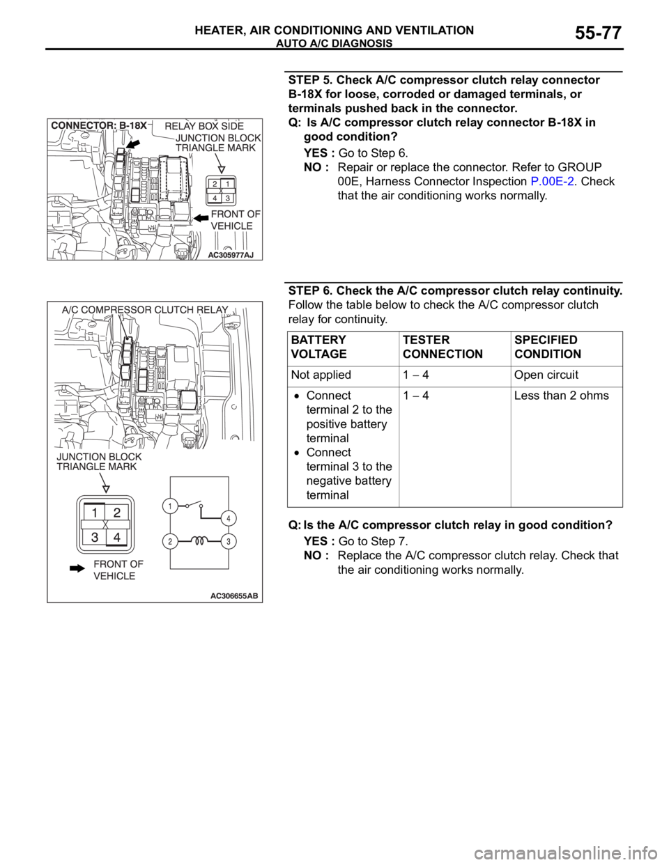
STEP 5. Check A/C compressor clutch relay connector
B-18X for loose, corroded or damaged terminals, or
terminals pushed back in the connector.
Q: Is A/C compressor clutch relay connector B-18X in
good condition?
YES : Go to Step 6.
NO : Repair or replace the connector. Refer to GROUP
00E, Harness Connector Inspection P.00E-2. Check
that the air conditioning works normally.
STEP 6. Check the A/C compressor clutch relay continuity.
Follow the table below to check the A/C compressor clutch
relay for continuity.
Q: Is the A/C compressor clutch relay in good condition?
YES : Go to Step 7.
NO : Replace the A/C compressor clutch relay. Check that
the air conditioning works normally.
BATTERY
VOLTAGETESTER
CONNECTIONSPECIFIED
CONDITION
Not applied 1
4 Open circuit
Connect
terminal 2 to the
positive battery
terminal
Connect
terminal 3 to the
negative battery
terminal1
4 Less than 2 ohms
Page 780 of 1500
AUTO A/C DIAGNOSIS
HEATER, AIR CONDITIONING AND VENTILATION55-79
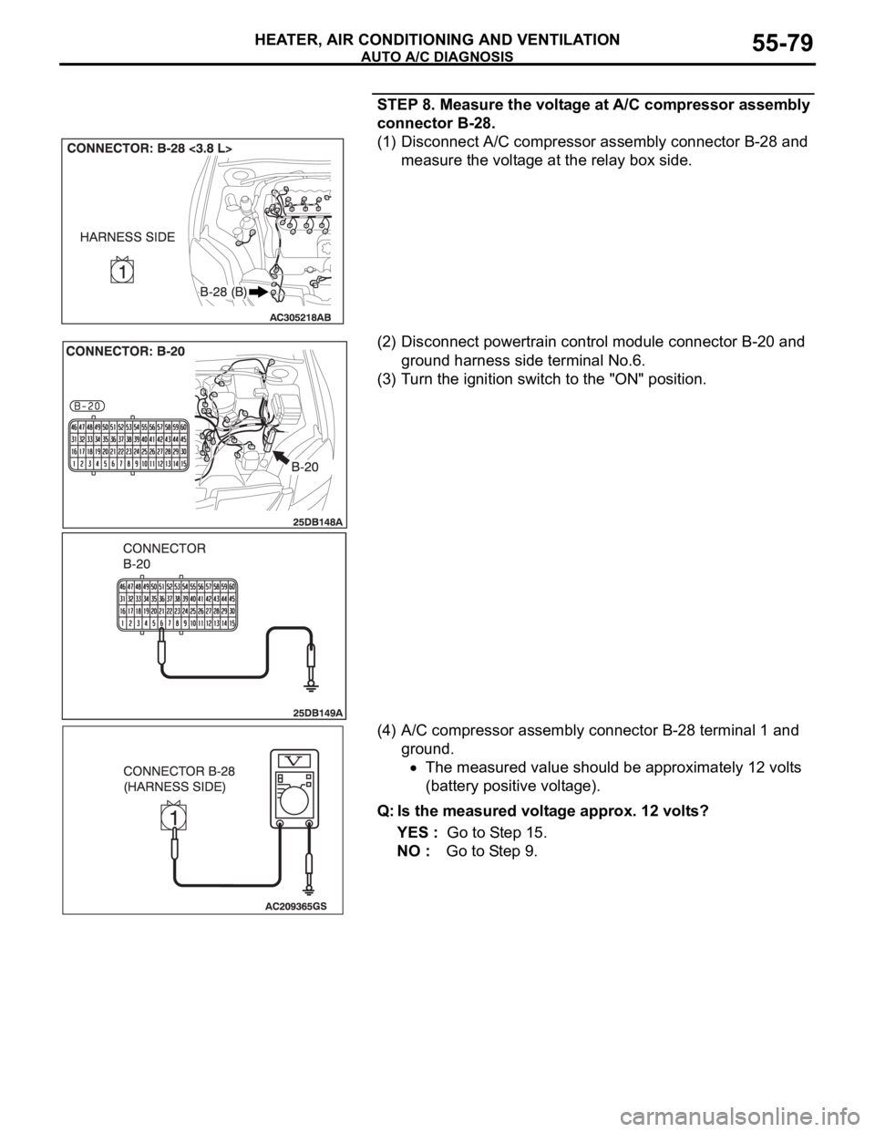
STEP 8. Measure the voltage at A/C compressor assembly
connector B-28.
(1) Disconnect A/C compressor assembly connector B-28 and
measure the voltage at the relay box side.
(2) Disconnect powertrain control module connector B-20 and
ground harness side terminal No.6.
(3) Turn the ignition switch to the "ON" position.
(4) A/C compressor assembly connector B-28 terminal 1 and
ground.
The measured value should be approximately 12 volts
(battery positive voltage).
Q: Is the measured voltage approx. 12 volts?
YES : Go to Step 15.
NO : Go to Step 9.
Page 781 of 1500
AUTO A/C DIAGNOSIS
HEATER, AIR CONDITIONING AND VENTILATION55-80
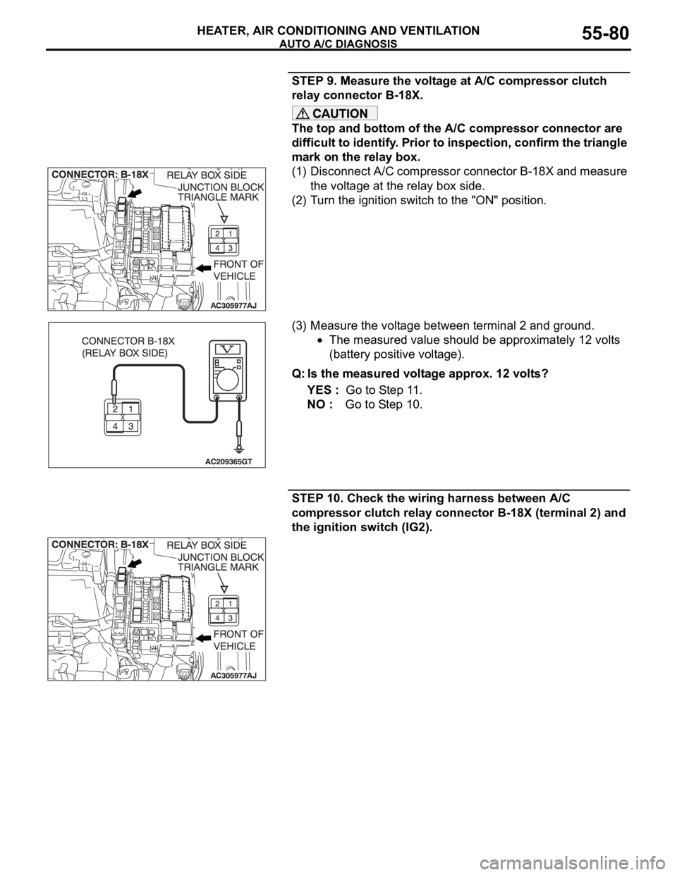
STEP 9. Measure the voltage at A/C compressor clutch
relay connector B-18X.
The top and bottom of the A/C compressor connector are
difficult to identify. Prior to inspection, confirm the triangle
mark on the relay box.
(1) Disconnect A/C compressor connector B-18X and measure
the voltage at the relay box side.
(2) Turn the ignition switch to the "ON" position.
(3) Measure the voltage between terminal 2 and ground.
The measured value should be approximately 12 volts
(battery positive voltage).
Q: Is the measured voltage approx. 12 volts?
YES : Go to Step 11.
NO : Go to Step 10.
STEP 10. Check the wiring harness between A/C
compressor clutch relay connector B-18X (terminal 2) and
the ignition switch (IG2).
Page 783 of 1500
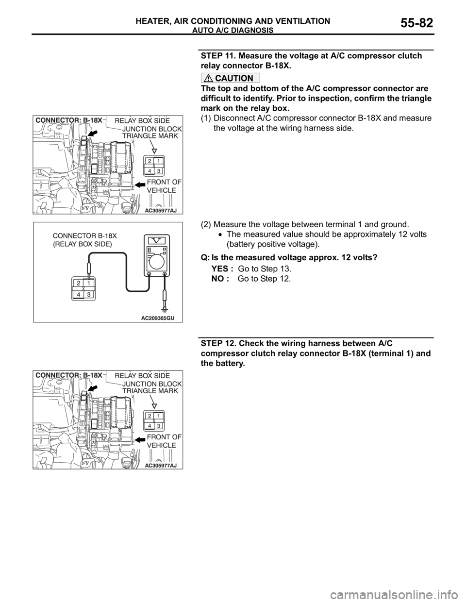
AUTO A/C DIAGNOSIS
HEATER, AIR CONDITIONING AND VENTILATION55-82
STEP 11. Measure the voltage at A/C compressor clutch
relay connector B-18X.
The top and bottom of the A/C compressor connector are
difficult to identify. Prior to inspection, confirm the triangle
mark on the relay box.
(1) Disconnect A/C compressor connector B-18X and measure
the voltage at the wiring harness side.
(2) Measure the voltage between terminal 1 and ground.
The measured value should be approximately 12 volts
(battery positive voltage).
Q: Is the measured voltage approx. 12 volts?
YES : Go to Step 13.
NO : Go to Step 12.
STEP 12. Check the wiring harness between A/C
compressor clutch relay connector B-18X (terminal 1) and
the battery.