Start system MITSUBISHI 380 2005 Owner's Guide
[x] Cancel search | Manufacturer: MITSUBISHI, Model Year: 2005, Model line: 380, Model: MITSUBISHI 380 2005Pages: 1500, PDF Size: 47.87 MB
Page 1002 of 1500
STARTING SYSTEM
ENGINE ELECTRICAL16-25
.
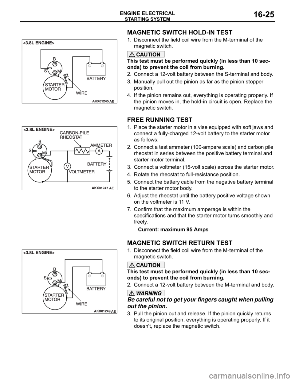
MAGNETIC SWITCH HOLD-IN TEST
1. Disconnect the field coil wire from the M-terminal of the
magnetic switch.
This test must be performed quickly (in less than 10 sec-
onds) to prevent the coil from burning.
2. Connect a 12-volt battery between the S-terminal and body.
3. Manually pull out the pinion as far as the pinion stopper
position.
4. If the pinion remains out, everything is operating properly. If
the pinion moves in, the hold-in circuit is open. Replace the
magnetic switch.
.
FREE RUNNING TEST
1. Place the starter motor in a vise equipped with soft jaws and
connect a fully-charged 12-volt battery to the starter motor
as follows:
2. Connect a test ammeter (100-ampere scale) and carbon pile
rheostat in series between the positive battery terminal and
starter motor terminal.
3. Connect a voltmeter (15-volt scale) across the starter motor.
4. Rotate the rheostat to full-resistance position.
5. Connect the battery cable from the negative battery terminal
to the starter motor body.
6. Adjust the rheostat until the battery positive voltage shown
on the voltmeter is 11 V.
7. Confirm that the maximum amperage is within the
specifications and that the starter motor turns smoothly and
freely.
Current: maximum 95 Amps
.
MAGNETIC SWITCH RETURN TEST
1. Disconnect the field coil wire from the M-terminal of the
magnetic switch.
This test must be performed quickly (in less than 10 sec-
onds) to prevent the coil from burning.
2. Connect a 12-volt battery between the M-terminal and body.
Be careful not to get your fingers caught when pulling
out the pinion.
3. Pull the pinion out and release. If the pinion quickly returns
to its original position, everything is operating properly. If it
doesn't, replace the magnetic switch.
Page 1003 of 1500
STARTING SYSTEM
ENGINE ELECTRICAL16-26
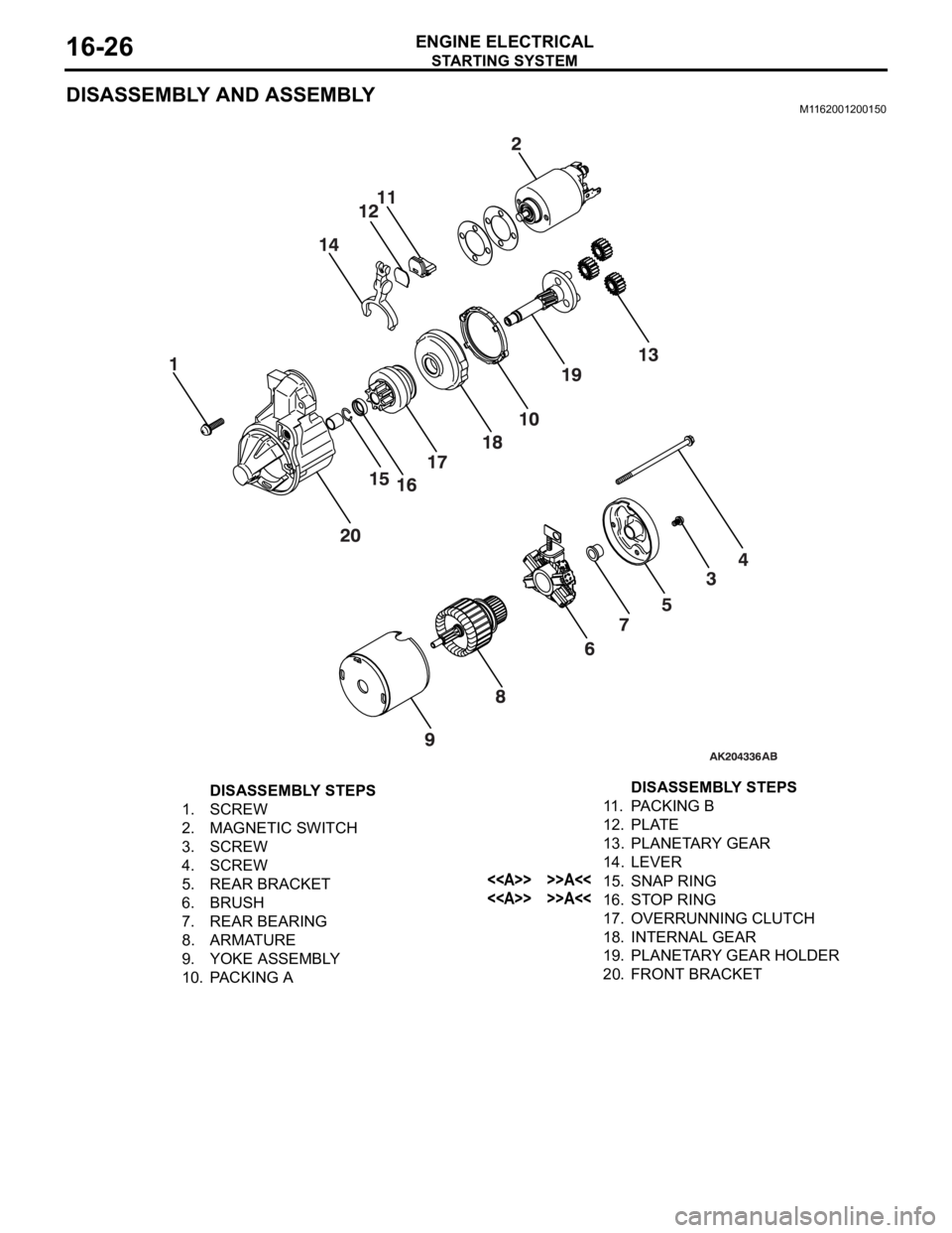
DISASSEMBLY AND ASSEMBLYM1162001200150
DISASSEMBLY STEPS
1. SCREW
2. MAGNETIC SWITCH
3. SCREW
4. SCREW
5. REAR BRACKET
6. BRUSH
7. REAR BEARING
8. ARMATURE
9. YOKE ASSEMBLY
10. PACKING A11 . PA C K I N G B
12. PLATE
13. PLANETARY GEAR
14. LEVER
<> >>A<<15. SNAP RING
<> >>A<<16. STOP RING
17. OVERRUNNING CLUTCH
18. INTERNAL GEAR
19. PLANETARY GEAR HOLDER
20. FRONT BRACKETDISASSEMBLY STEPS
Page 1004 of 1500
Page 1005 of 1500
STARTING SYSTEM
ENGINE ELECTRICAL16-28
INSPECTIONM1162001300102.
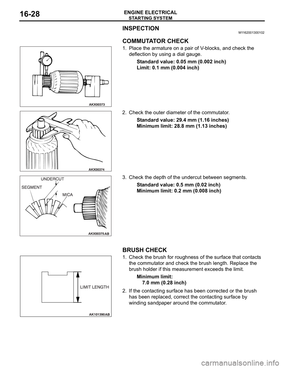
COMMUTATOR CHECK
1. Place the armature on a pair of V-blocks, and check the
deflection by using a dial gauge.
Standard value: 0.05 mm (0.002 inch)
Limit: 0.1 mm (0.004 inch)
2. Check the outer diameter of the commutator.
Standard value: 29.4 mm (1.16 inches)
Minimum limit: 28.8 mm (1.13 inches)
3. Check the depth of the undercut between segments.
Standard value: 0.5 mm (0.02 inch)
Minimum limit: 0.2 mm (0.008 inch)
.
BRUSH CHECK
1. Check the brush for roughness of the surface that contacts
the commutator and check the brush length. Replace the
brush holder if this measurement exceeds the limit.
Minimum limit:
7.0 mm (0.28 inch)
2. If the contacting surface has been corrected or the brush
has been replaced, correct the contacting surface by
winding sandpaper around the commutator.
.
Page 1006 of 1500
STARTING SYSTEM
ENGINE ELECTRICAL16-29
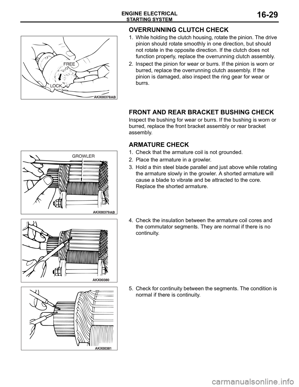
OVERRUNNING CLUTCH CHECK
1. While holding the clutch housing, rotate the pinion. The drive
pinion should rotate smoothly in one direction, but should
not rotate in the opposite direction. If the clutch does not
function properly, replace the overrunning clutch assembly.
2. Inspect the pinion for wear or burrs. If the pinion is worn or
burred, replace the overrunning clutch assembly. If the
pinion is damaged, also inspect the ring gear for wear or
burrs.
.
FRONT AND REAR BRACKET BUSHING CHECK
Inspect the bushing for wear or burrs. If the bushing is worn or
burred, replace the front bracket assembly or rear bracket
assembly.
.
ARMATURE CHECK
1. Check that the armature coil is not grounded.
2. Place the armature in a growler.
3. Hold a thin steel blade parallel and just above while rotating
the armature slowly in the growler. A shorted armature will
cause a blade to vibrate and be attracted to the core.
Replace the shorted armature.
4. Check the insulation between the armature coil cores and
the commutator segments. They are normal if there is no
continuity.
5. Check for continuity between the segments. The condition is
normal if there is continuity.
Page 1015 of 1500

SPECIFICATIONS
ENGINE ELECTRICAL16-38
SPECIFICATIONS
FASTENER TIGHTENING SPECIFICATIONSM1161002100506
GENERAL SPECIFICATIONSM1161000200411
ITEM SPECIFICATION
Charging system
Alternator bracket bolt49
9 Nm (36 7 ft-lb)
Alternator bolt49
9 Nm (36 7 ft-lb)
Alternator terminal nut12
2 Nm (102 22 in-lb)
Ignition system
Camshaft position sensor bolt 11
1 Nm (98 8 in-lb)
Crankshaft position sensor bolt 9.0
1.0 Nm (80 9 in-lb)
Ignition coil bolt 10
2 Nm (89 17 in-lb)
Knock sensor 23
2 Nm (17 1 ft-lb)
Spark plug 25
4 Nm (18 3 ft-lb)
Starting system
Starter bolt 30
3 Nm (23 2 ft-lb)
Starter cover bolt 4.9
1.0 Nm (44 8 in-lb)
Starter terminal nut 12
2 Nm (102 22 in-lb)
ITEMS SPECIFICATIONS
Alternator
Type Positive battery positive voltage sensing
Identification number
Part No. MN180394
Rated output V/A 12/110
Voltage regulator Electronic built-in type
Starter Motor
Type Reduction drive with planetary gear
Identification number M000T31172
Part No. 1810A090
Rated output kW/V 1.2/12
Number of pinion teeth 8
Ignition Coil
Type Molded 6 coil
Spark Plugs
BOSCH FR8DI30
Page 1101 of 1500

DOOR
BODY42-34
CIRCUIT BREAKER (INCORPORATED IN THE
POWER WINDOW MOTOR) INSPECTION
M1429001000284
1. Pull the power window switch to the UP position to fully
close the door window glass, and keep pulling the switch for
an additional ten seconds.
2. Release the power window switch from the UP position and
immediately press it to the DOWN position. The condition of
the circuit breaker is good if the door window glass starts to
move downwards within about 60 seconds.
POWER WINDOW CHECKM1429004400214
1. Operate the power window switch of each door to verify that
the power windows operate properly. If they don't, then
troubleshoot as described in GROUP 54B, SWS Diagnosis
P.54B-57.
2. Turn ON the power window lock switch of the power window
main switch. Then operate the passenger's door and rear
door power window sub-switches to ensure that they do not
operate. If they do, replace the power window main switch
(Refer to P.42-39).
CENTRAL DOOR LOCKING SYSTEM
INSPECTION
M1427001100144
Check the following. Troubleshoot if operations malfunction
(Refer to GROUP 54B, SWS Diagnosis P.54B-57).
Insert the key into the driver's key cylinder and turn once to
the unlock side to unlock the driver's door and fuel lid door.
Turn the key once again to the unlock side to unlock all
doors and fuel lid door.
All doors and fuel lid door can be locked using the door lock
switch built into the front power window (main or sub
switch.
Page 1169 of 1500
BASIC BRAKE SYSTEM DIAGNOSIS
BASIC BRAKE SYSTEM35A-4
STEP 2. Check disc brake pistons for smooth
operation.
(1) With engine not running, depress the brake pedal
rapidly several times to deplete booster vacuum
reserves.
(2) Test each disc brake assembly one at a time.
a. Remove the lower caliper bolt, then remove
caliper from mount.
b. Have an assistant slowly depress the brake
pedal. Confirm piston(s) extend slowly and
smoothly with no jumpiness. Repeat for each
disc brake assembly.
Q: Do (does) the piston(s) move correctly?
YES :
Go to Step 3.
NO : Disassemble and inspect the brake
assembly (Front: refer to P.35A-33, Rear:
refer to P.35A-36). Then go to Step 5.
STEP 3. Check brake disc(s) for runout.
Refer to P.35A-19.
Q: Is runout outside of specifications?
YES :
Repair or replace the brake disc(s) as
necessary. Then go to Step 5.
NO : Go to Step 4.
STEP 4. Check brake discs for correct thickness.
Refer to P.35A-19.
Q: Is the thickness outside of specifications?
YES :
Repair or replace the brake disc(s) as
necessary. Then go to Step 5.
NO : Perform the brake line bleeding. Then go to
St e p 5.
STEP 5. Retest the system.
Q: Is the symptom eliminated?
YES :
The procedure is complete.
NO : Start over at Step 1. If a new symptom
appears, refer to the appropriate symptom
chart.
INSPECTION PROCEDURE 2: Insufficient Braking Power
.
DIAGNOSIS
STEP 1. Check that the specified brake fluid is
used, its level is correct, and no contamination is
found.
Q: Is there a fault?
YES :
Refill or replace with the specified brake
fluid DOT 3 or DOT 4. Bleed the brakes if
necessary (Refer to P.35A-16). Then go to
Step 7.
NO : Go to Step 2.
STEP 2. Check for spongy (not firm) brakes.
(1) With engine not running, depress the brake pedal
rapidly several times to deplete the booster
vacuum reserve.
(2) With the brake pedal fully released, depress the
brake pedal slowly until it stops.
(3) With a measuring device (ruler, etc.) next to the
brake pedal, depress the pedal firmly and
measure the distance the pedal traveled.
Q: Is the distance greater than 20 mm (0.8 inch)?
YES :
Bleed the brakes to remove air in the fluid
(Refer to P.35A-16). Then go to Step 7.
NO : Go to Step 3.
STEP 3. Check the brake booster function.
Refer to P.35A-14.
Q: Is there a fault?
YES :
Replace the brake booster. Then go to Step
7.
NO : Go to Step 4.
Page 1170 of 1500
BASIC BRAKE SYSTEM DIAGNOSIS
BASIC BRAKE SYSTEM35A-5
STEP 4. Check for pinched or restricted brake
tube or hose.
Q: Is there a pinched or restricted brake tube or hose?
YES :
Replace that complete section of brake tube
or brake hose. Then go to Step 7.
NO : Go to Step 5.
STEP 5. Check for oil, water, etc., on the pad
contact surfaces of all brakes.
Q: Is oil, water, etc., on the pad contact surface?
YES :
Replace the part and determine the
source/cause of foreign material. Recheck
symptom. Then go to Step 7.
NO : The procedure is complete. If condition
persists for vehicles without ABS, go to Step
6.
STEP 7. Recheck symptom.
Q: Is the symptom eliminated?
YES :
The procedure is complete.
NO : Start over at step 1. If a new symptom
surfaces, refer to the appropriate symptom
chart.
INSPECTION PROCEDURE 3: Increased Pedal Stroke (Reduced Pedal-to-Floor Board Clearance)
.
DIAGNOSIS
STEP 1. Check for spongy (not firm) brakes.
(1) With engine not running, depress the brake pedal
rapidly several times to deplete booster vacuum
reserve.
(2) With the brake pedal fully released, depress the
brake pedal slowly until it stops.
(3) With a measuring device (ruler, etc.) next to the
brake pedal, depress the pedal firmly and
measure the distance the pedal traveled.
Q: Is the distance greater than 20 mm (0.8 inch)?
YES :
Bleed the brakes to remove air in the fluid
(Refer to P.35A-16). Then go to Step 7.
NO : Go to Step 2.
STEP 2. Check the pad for wear.
Refer to P.35A-17.
Q: Is the pad thickness outside of specifications?
YES :
Replace the part. Then go to Step 7.
NO : Go to Step 3.
STEP 3. Check the vacuum hose and check valve
for damage.
Refer to P.35A-15.
Q: Is there a damage?
YES :
Replace the part. Then go to Step 7.
NO : Go to Step 4.
STEP 4. Check the master cylinder function.
Refer to P.35A-23.
Q: Is there a fault?
YES :
Repair it. Then go to Step 7.
NO : Go to Step 5.
STEP 5. Check for brake fluid leaks.
Q: Is there a leak?
YES :
Check the connection for looseness,
corrosion, etc. Clean and repair as
necessary. If leaking in any tube or hose
section, replace the complete tube or hose.
Then go to Step 7 .
NO : Go to Step 6.
STEP 6. Check for excessive clearance between
the push rod and primary piston.
Refer to P.35A-26.
Q: Is the clearance outside of specifications?
YES :
Adjust the clearance. Then go to Step 7.
NO : Go to Step 7.
STEP 7. Recheck symptom.
Q: Is the symptom eliminated?
YES :
The procedure is complete.
NO : Start over at step 1. If a new symptom
surfaces, refer to the symptom chart.
Page 1172 of 1500
BASIC BRAKE SYSTEM DIAGNOSIS
BASIC BRAKE SYSTEM35A-7
STEP 6. Check the master cylinder piston return spring for
damage and return port for clogging.
Refer to P.35A-28.
Q: Is there damage?
YES : Replace the part. Then go to Step 9.
NO : Go to Step 7.
STEP 7. Check port for clogging.
Q: Is the port clogged?
YES : Repair it. Then go to Step 9.
NO : Go to Step 8.
STEP 8. Check disc brake pistons for sticking.
Depress the brake pedal, then release. Confirm each wheel
spins freely.
Q: Does any wheel stick?
YES : Inspect that brake assembly. Then go to Step 9.
NO : Go to Step 9.
STEP 9. Recheck symptom.
Q: Is the symptom eliminated?
YES : The procedure is complete.
NO : Start over at step 1. If a new symptom surfaces, refer
to the symptom chart.
INSPECTION PROCEDURE 5: Scraping or Grinding Noise when Brakes are Applied
.
DIAGNOSIS
STEP 1. Check the front brakes, then rear brakes, for
metal-to-metal condition.
Q: Is any metal-to-metal contact evident?
YES : Repair or replace the components. Then go to Step 6.
NO : Go to Step 2.
STEP 2. Check for interference between the caliper and
wheel.
Q: Is there any interference?
YES : Repair or replace the part. Then go to Step 6.
NO : Go to Step 3.