Start system MITSUBISHI 380 2005 Repair Manual
[x] Cancel search | Manufacturer: MITSUBISHI, Model Year: 2005, Model line: 380, Model: MITSUBISHI 380 2005Pages: 1500, PDF Size: 47.87 MB
Page 1265 of 1500
MAINTENANCE SERVICE
GENERAL00-44
8. EXHAUST SYSTEM (CONNECTIONS PORTION
OF MUFFLER, MUFFLER PIPES AND
CONVERTER HEAT SHIELDS) (CHECK AND
SERVICE AS REQUIRED)
M1001005800299
1. Check for holes and exhaust gas leaks due to damage,
corrosion, etc.
2. Check the joints and connections for looseness and exhaust
gas leaks.
3. Check the rubber hangers and brackets for damage.
9. ENGINE OIL (CHANGE)M1001002600360
Use the specified oil. (Refer to P.00-35.)
Use care as oil could be hot.
1. After warming up the engine, remove the oil filler cap.
2. Remove the drain plug to allow the engine oil to drain.
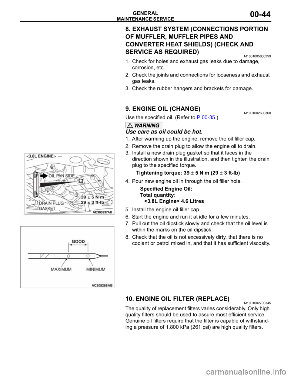
3. Install a new drain plug gasket so that it faces in the
direction shown in the illustration, and then tighten the drain
plug to the specified torque.
Tightening torque: 39
5 Nm (29 3 ft-lb)
4. Pour new engine oil in through the oil filler hole.
Specified Engine Oil:
To ta l q u a n t i t y :
<3.8L Engine> 4.6 Litres
5. Install the engine oil filler cap.
6. Start the engine and run it at idle for a few minutes.
7. Pull out the oil dipstick slowly and check that the oil level is
within the marks on the oil dipstick.
8. Check that the oil is not excessively dirty, that there is no
coolant or petrol mixed in, and that it has sufficient viscosity.
10. ENGINE OIL FILTER (REPLACE)M1001002700345
The quality of replacement filters varies considerably. Only high
quality filters should be used to assure most efficient service.
Genuine oil filters require that the filter is capable of withstand-
ing a pressure of 1,800 kPa (261 psi) are high quality filters.
.
Page 1282 of 1500
TRACTION CONTROL SYSTEM (TCL) DIAGNOSIS
TRACTION CONTROL SYSTEM (TCL)13C-3
TRACTION CONTROL SYSTEM (TCL) DIAGNOSIS
INTRODUCTION TO TRACTION CONTROL SYSTEM (TCL) DIAGNOSISM1136004600026
TCL Diagnostic Trouble Code Detection
Conditions
TCL diagnostic trouble codes (TCL DTCs) are set
under different conditions, depending on the mal-
function detected. Most TCL DTCs will only be set
during vehicle operation. Some TCL DTCs will also
be set during the TCL self-check immediately after
the engine is started. When you check if an TCL DTC will be displayed again after the DTC has been
erased, you should recreate the TCL DTC set condi-
tions. Depending on the detection timing and set
conditions for the specific TCL DTC, you must either
drive the vehicle or turn the engine off and restart it.
To set the proper conditions for that DTC again, refer
to "TCL DTC SET CONDITIONS" for each TCL DTC
that you are trying to reset.
TROUBLESHOOTING STRATEGYM1136003100062
Use these steps to plan your diagnostic strategy. If
you follow them carefully, you will check most of the
possible causes of a TCL problem.
1. Gather information from the customer.
2. Verify that the condition described by the
customer exists.
3. Check the vehicle for any TCL DTC. (Refer to
P.13C-3, Diagnosis Function
How to Read and
Erase Diagnostic Trouble Codes).
4. If you can verify the condition but no TCL DTCs
are set, and the malfunction may be intermittent.
(Refer to GROUP 00, How to Use
Troubleshooting/Inspection Service Points
How
to Cope with Intermittent Malfunctions P.00-14).
5. If you can verify the condition but there is no TCL
DTCs, or the system cannot communicate with
diagnostic tool MB991958 (MUT-III sub
assembly), and find the fault. (Refer to P.13C-23,
Symptom Chart).6. If there is a TCL DTC, record the number of the
code, then erase the code from vehicle memory
using the diagnostic tool MB991958 (MUT-III sub
assembly). (Refer to P.13C-3, Diagnosis Function
How to Read and Erase Diagnostic Trouble
Codes).
7. Re-create the TCL DTC set conditions to see if
the same TCL DTC will set again. (Refer to
P.13C-3, Diagnosis Function
How to Read and
Erase Diagnostic Trouble Codes).
If the same TCL DTC sets again, perform the
diagnostic procedures for the set code. (Refer to
P.13C-8, Diagnostic Trouble Code Chart).
NOTE: If the ABS-8 ECU or the active wheel
speed sensor are disconnected, or if the wir-
ing is an open/ short circuit, the ABS 8 ECU
will shut off power supply to the respective
wheel speed sensor. All other wheel speed
sensors will operate normally. To restore the
power supply, the ignition switch must be
turned to the "OFF" position then to the "ON"
position again.
DIAGNOSIS FUNCTIONM1136003200025
HOW TO CONNECT THE DIAGNOSTIC TOOL
(MUT-III)
Required Special Tools:
MB991958: Diagnostic Tool (MUT-III Sub Assembly)
MB991824: Vehicle Communication Interface (V.C.I.)
MB991827: MUT-III USB Cable
MB991910: MUT-III Main Harness A
Page 1283 of 1500
TRACTION CONTROL SYSTEM (TCL) DIAGNOSIS
TRACTION CONTROL SYSTEM (TCL)13C-4
To prevent damage to diagnostic tool MB991958, always
turn the ignition switch to the "LOCK" (OFF) position
before connecting or disconnecting diagnostic tool
MB991958.
1. Ensure that the ignition switch is at the "LOCK" (OFF)
position.
2. Start up the personal computer.
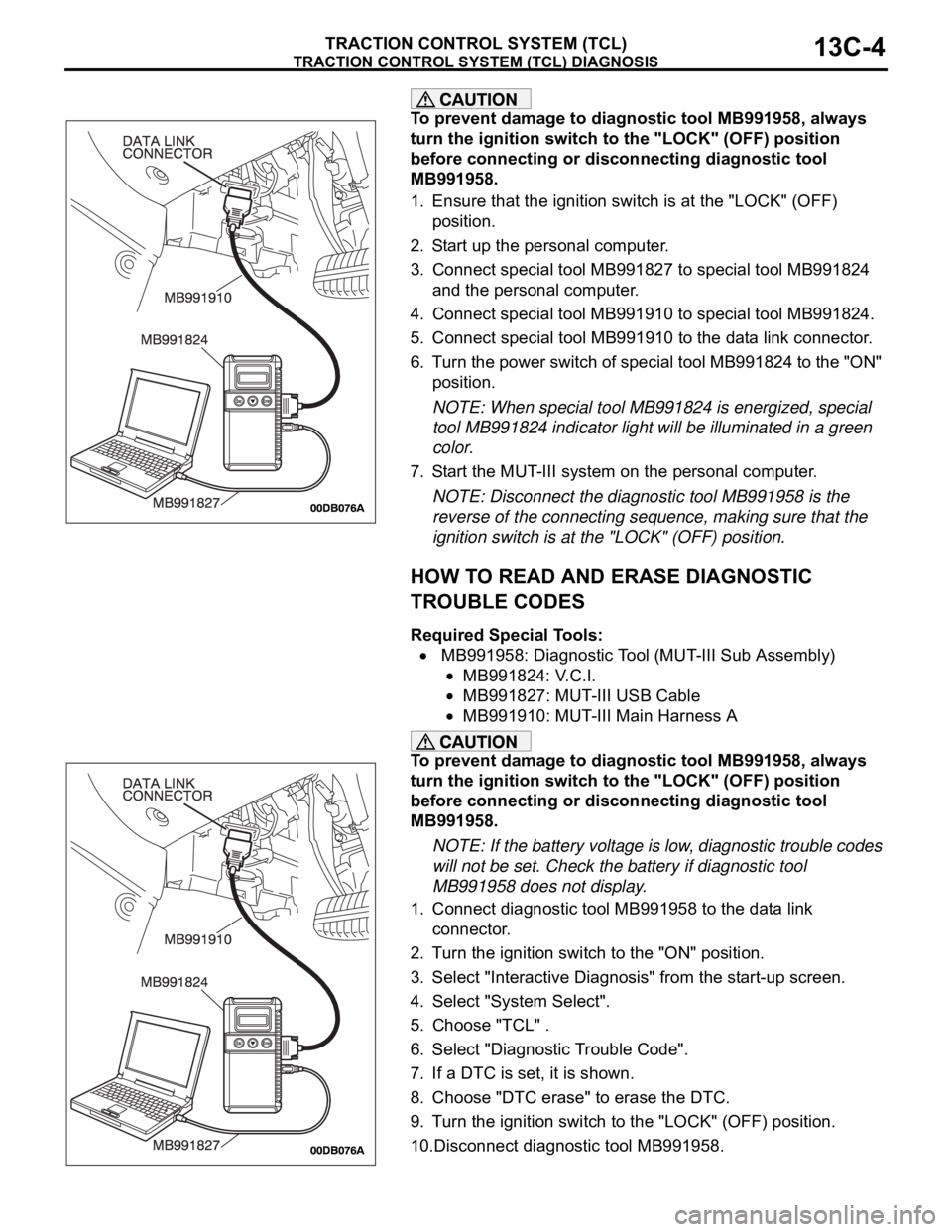
3. Connect special tool MB991827 to special tool MB991824
and the personal computer.
4. Connect special tool MB991910 to special tool MB991824.
5. Connect special tool MB991910 to the data link connector.
6. Turn the power switch of special tool MB991824 to the "ON"
position.
NOTE: When special tool MB991824 is energized, special
tool MB991824 indicator light will be illuminated in a green
color.
7. Start the MUT-III system on the personal computer.
NOTE: Disconnect the diagnostic tool MB991958 is the
reverse of the connecting sequence, making sure that the
ignition switch is at the "LOCK" (OFF) position.
HOW TO READ AND ERASE DIAGNOSTIC
TROUBLE CODES
Required Special Tools:
MB991958: Diagnostic Tool (MUT-III Sub Assembly)
MB991824: V.C.I.
MB991827: MUT-III USB Cable
MB991910: MUT-III Main Harness A
To prevent damage to diagnostic tool MB991958, always
turn the ignition switch to the "LOCK" (OFF) position
before connecting or disconnecting diagnostic tool
MB991958.
NOTE: If the battery voltage is low, diagnostic trouble codes
will not be set. Check the battery if diagnostic tool
MB991958 does not display.
1. Connect diagnostic tool MB991958 to the data link
connector.
2. Turn the ignition switch to the "ON" position.
3. Select "Interactive Diagnosis" from the start-up screen.
4. Select "System Select".
5. Choose "TCL" .
6. Select "Diagnostic Trouble Code".
7. If a DTC is set, it is shown.
8. Choose "DTC erase" to erase the DTC.
9. Turn the ignition switch to the "LOCK" (OFF) position.
10.Disconnect diagnostic tool MB991958.
Page 1284 of 1500
TRACTION CONTROL SYSTEM (TCL) DIAGNOSIS
TRACTION CONTROL SYSTEM (TCL)13C-5
HOW TO READ DATA LIST
Required Special Tools:
MB991958: Diagnostic Tool (MUT-III Sub Assembly)
MB991824: V.C.I.
MB991827: MUT-III USB Cable
MB991910: MUT-III Main Harness A
To prevent damage to diagnostic tool MB991958, always
turn the ignition switch to the "LOCK" (OFF) position
before connecting or disconnecting diagnostic tool
MB991958.
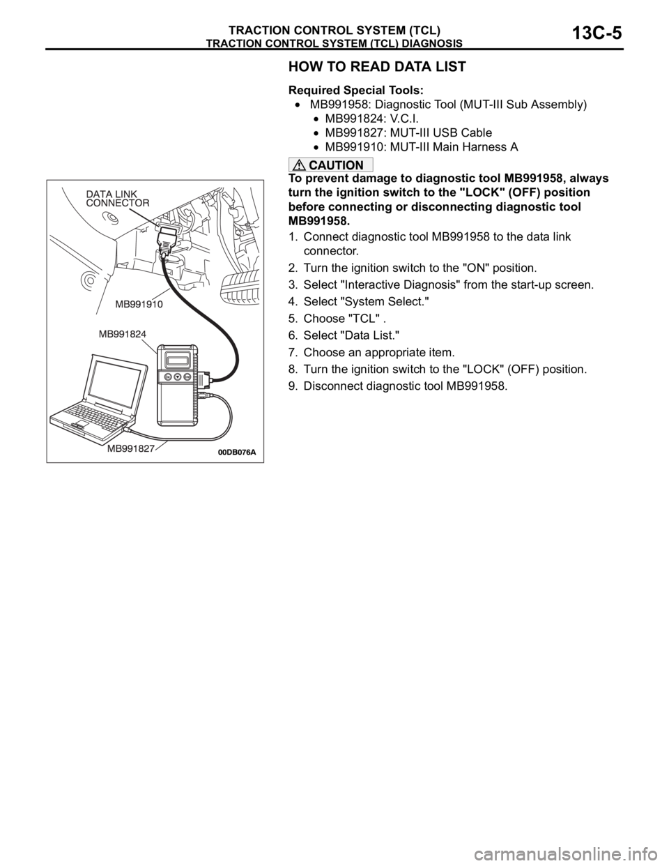
1. Connect diagnostic tool MB991958 to the data link
connector.
2. Turn the ignition switch to the "ON" position.
3. Select "Interactive Diagnosis" from the start-up screen.
4. Select "System Select."
5. Choose "TCL" .
6. Select "Data List."
7. Choose an appropriate item.
8. Turn the ignition switch to the "LOCK" (OFF) position.
9. Disconnect diagnostic tool MB991958.
Page 1285 of 1500
TRACTION CONTROL SYSTEM (TCL) DIAGNOSIS
TRACTION CONTROL SYSTEM (TCL)13C-6
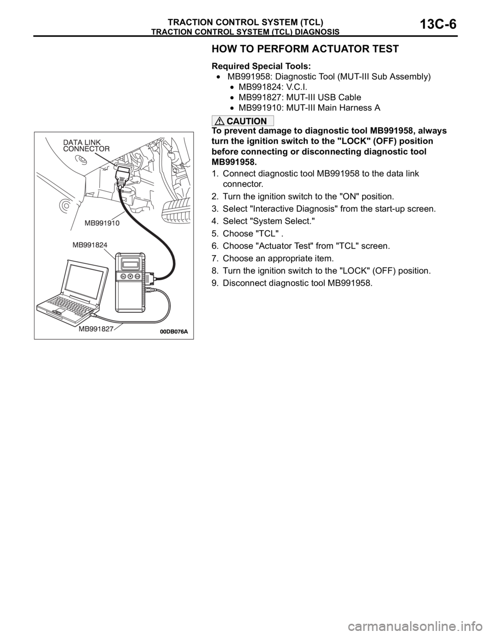
HOW TO PERFORM ACTUATOR TEST
Required Special Tools:
MB991958: Diagnostic Tool (MUT-III Sub Assembly)
MB991824: V.C.I.
MB991827: MUT-III USB Cable
MB991910: MUT-III Main Harness A
To prevent damage to diagnostic tool MB991958, always
turn the ignition switch to the "LOCK" (OFF) position
before connecting or disconnecting diagnostic tool
MB991958.
1. Connect diagnostic tool MB991958 to the data link
connector.
2. Turn the ignition switch to the "ON" position.
3. Select "Interactive Diagnosis" from the start-up screen.
4. Select "System Select."
5. Choose "TCL" .
6. Choose "Actuator Test" from "TCL" screen.
7. Choose an appropriate item.
8. Turn the ignition switch to the "LOCK" (OFF) position.
9. Disconnect diagnostic tool MB991958.
Page 1286 of 1500
TRACTION CONTROL SYSTEM (TCL) DIAGNOSIS
TRACTION CONTROL SYSTEM (TCL)13C-7
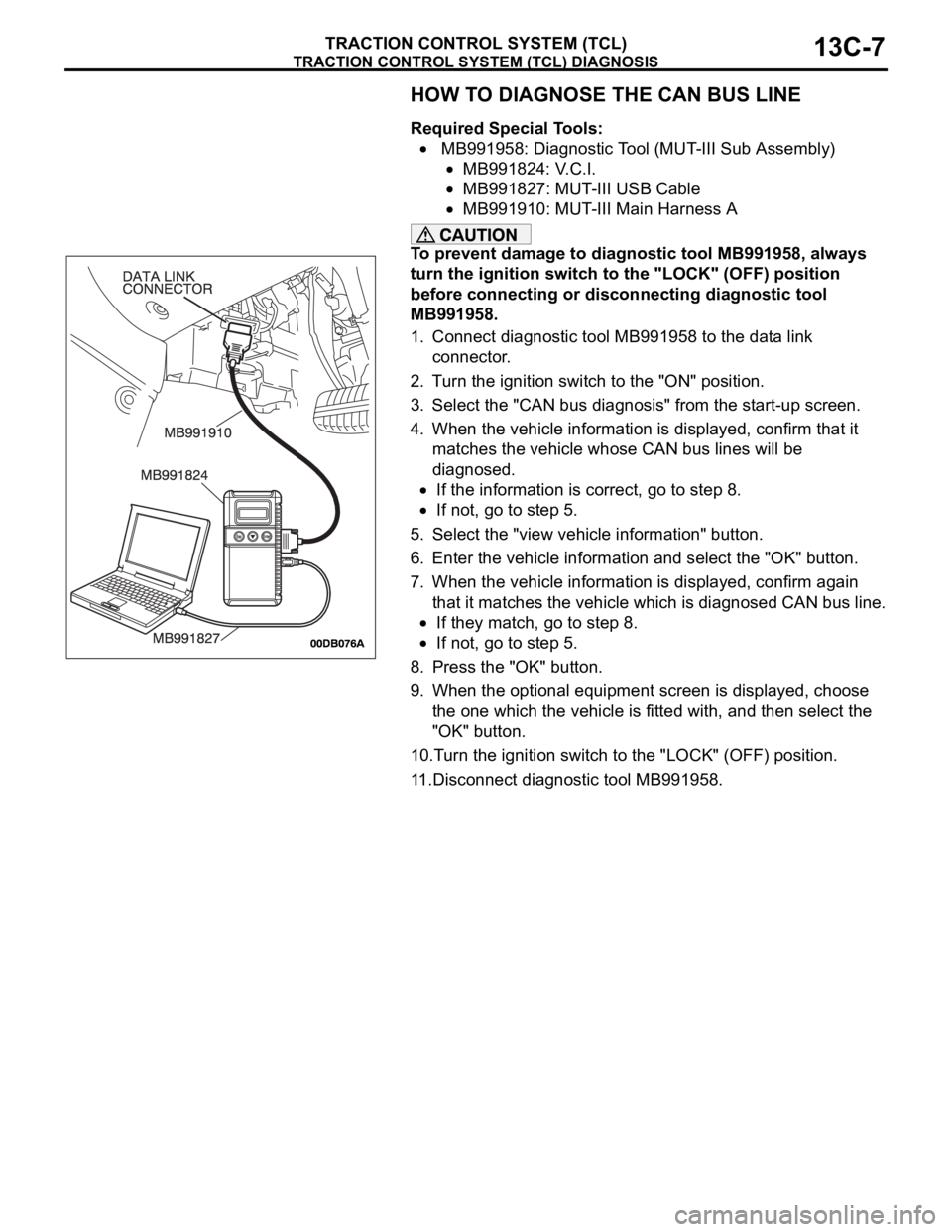
HOW TO DIAGNOSE THE CAN BUS LINE
Required Special Tools:
MB991958: Diagnostic Tool (MUT-III Sub Assembly)
MB991824: V.C.I.
MB991827: MUT-III USB Cable
MB991910: MUT-III Main Harness A
To prevent damage to diagnostic tool MB991958, always
turn the ignition switch to the "LOCK" (OFF) position
before connecting or disconnecting diagnostic tool
MB991958.
1. Connect diagnostic tool MB991958 to the data link
connector.
2. Turn the ignition switch to the "ON" position.
3. Select the "CAN bus diagnosis" from the start-up screen.
4. When the vehicle information is displayed, confirm that it
matches the vehicle whose CAN bus lines will be
diagnosed.
If the information is correct, go to step 8.
If not, go to step 5.
5. Select the "view vehicle information" button.
6. Enter the vehicle information and select the "OK" button.
7. When the vehicle information is displayed, confirm again
that it matches the vehicle which is diagnosed CAN bus line.
If they match, go to step 8.
If not, go to step 5.
8. Press the "OK" button.
9. When the optional equipment screen is displayed, choose
the one which the vehicle is fitted with, and then select the
"OK" button.
10.Turn the ignition switch to the "LOCK" (OFF) position.
11.Disconnect diagnostic tool MB991958.
Page 1302 of 1500
TRACTION CONTROL SYSTEM (TCL) DIAGNOSIS
TRACTION CONTROL SYSTEM (TCL)13C-23
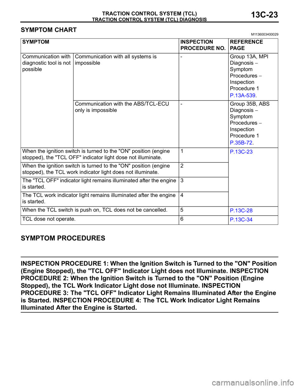
SYMPTOM CHARTM1136003400029
SYMPTOM PROCEDURES
INSPECTION PROCEDURE 1: When the Ignition Switch is Turned to the "ON" Position
(Engine Stopped), the "TCL OFF" Indicator Light does not Illuminate. INSPECTION
PROCEDURE 2: When the Ignition Switch is Turned to the "ON" Position (Engine
Stopped), the TCL Work Indicator Light dose not Illuminate. INSPECTION
PROCEDURE 3: The "TCL OFF" Indicator Light Remains Illuminated After the Engine
is Started. INSPECTION PROCEDURE 4: The TCL Work Indicator Light Remains
Illuminated After the Engine is Started.
SYMPTOM INSPECTION
PROCEDURE NO.REFERENCE
PA G E
Communication with
diagnostic tool is not
possibleCommunication with all systems is
impossible- Group 13A, MPI
Diagnosis
Symptom
Procedures
Inspection
Procedure 1
P.13A-539.
Communication with the ABS/TCL-ECU
only is impossible- Group 35B, ABS
Diagnosis
Symptom
Procedures
Inspection
Procedure 1
P.35B-72.
When the ignition switch is turned to the "ON" position (engine
stopped), the "TCL OFF" indicator light dose not illuminate.1
P.13C-23
When the ignition switch is turned to the "ON" position (engine
stopped), the TCL work indicator light does not illuminate.2
The "TCL OFF" indicator light remains illuminated after the engine
is started.3
The TCL work indicator light remains illuminated after the engine
is started.4
When the TCL switch is push on, TCL does not be cancelled. 5
P.13C-28
TCL dose not operate. 6
P.13C-34
Page 1307 of 1500
TRACTION CONTROL SYSTEM (TCL) DIAGNOSIS
TRACTION CONTROL SYSTEM (TCL)13C-28
STEP 4. Retest the system
Q: Turn the ignition switch to the "ON" position. Do the
"TCL OFF" indicator light and the TCL work indicator
light illuminate for three seconds, and then go out after
the engine starts?
YES : The procedure is complete.
NO : . Return to Step 1.
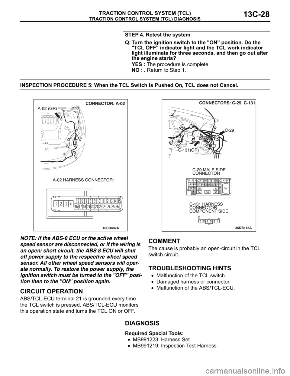
INSPECTION PROCEDURE 5: When the TCL Switch is Pushed On, TCL does not Cancel.
NOTE: If the ABS-8 ECU or the active wheel
speed sensor are disconnected, or if the wiring is
an open/ short circuit, the ABS 8 ECU will shut
off power supply to the respective wheel speed
sensor. All other wheel speed sensors will oper-
ate normally. To restore the power supply, the
ignition switch must be turned to the "OFF" posi-
tion then to the "ON" position again.
.
CIRCUIT OPERATION
ABS/TCL-ECU terminal 21 is grounded every time
the TCL switch is pressed. ABS/TCL-ECU monitors
this operation state and turns the TCL ON or OFF.
.
COMMENT
The cause is probably an open-circuit in the TCL
switch circuit.
.
TROUBLESHOOTING HINTS
Malfunction of the TCL switch.
Damaged harness or connector.
Malfunction of the ABS/TCL-ECU.
DIAGNOSIS
Required Special Tools:
MB991223: Harness Set
MB991219: Inspection Test Harness
Page 1317 of 1500
TRACTION CONTROL SYSTEM (TCL) DIAGNOSIS
TRACTION CONTROL SYSTEM (TCL)13C-38
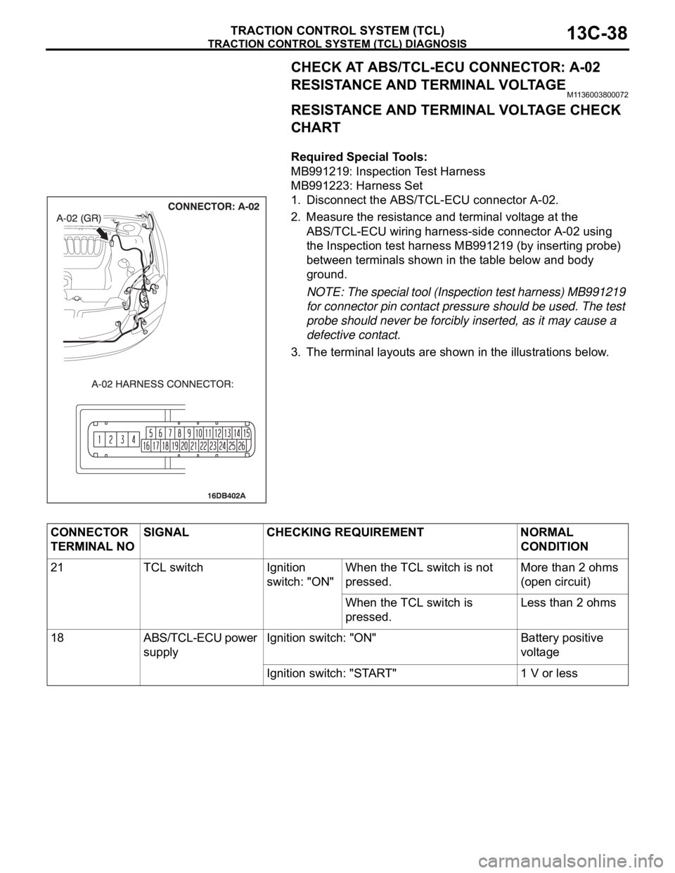
CHECK AT ABS/TCL-ECU CONNECTOR: A-02
RESISTANCE AND TERMINAL VOLTAGE
M1136003800072
RESISTANCE AND TERMINAL VOLTAGE CHECK
CHART
.
Required Special Tools:
MB991219: Inspection Test Harness
MB991223: Harness Set
1. Disconnect the ABS/TCL-ECU connector A-02.
2. Measure the resistance and terminal voltage at the
ABS/TCL-ECU wiring harness-side connector A-02 using
the Inspection test harness MB991219 (by inserting probe)
between terminals shown in the table below and body
ground.
NOTE: The special tool (Inspection test harness) MB991219
for connector pin contact pressure should be used. The test
probe should never be forcibly inserted, as it may cause a
defective contact.
3. The terminal layouts are shown in the illustrations below.
CONNECTOR
TERMINAL NOSIGNAL CHECKING REQUIREMENT NORMAL
CONDITION
21 TCL switch Ignition
switch: "ON" When the TCL switch is not
pressed.More than 2 ohms
(open circuit)
When the TCL switch is
pressed.Less than 2 ohms
18 ABS/TCL-ECU power
supplyIgnition switch: "ON" Battery positive
voltage
Ignition switch: "START" 1 V or less
Page 1326 of 1500
ON-VEHICLE SERVICE
TRACTION CONTROL SYSTEM (TCL)13C-47
ON-VEHICLE SERVICE
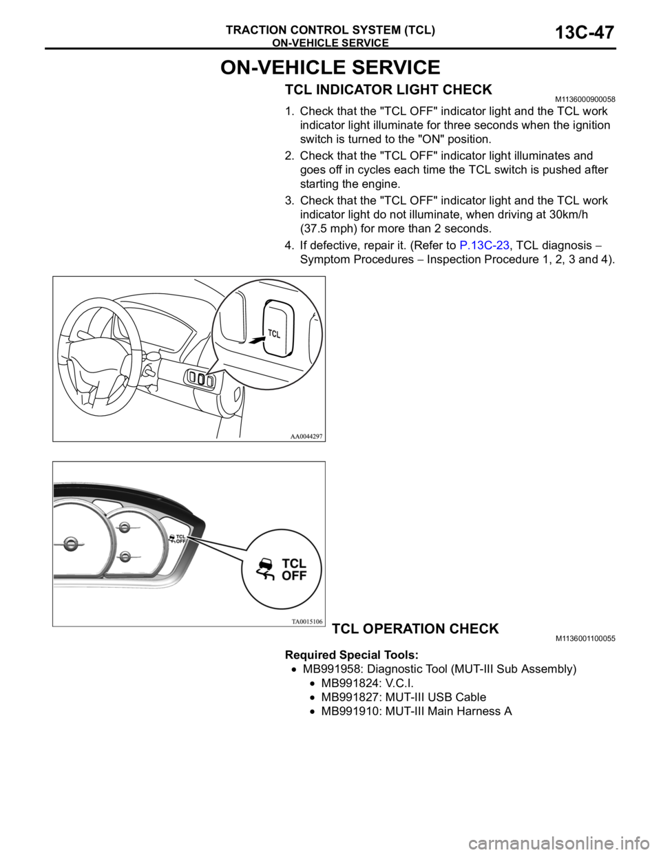
TCL INDICATOR LIGHT CHECKM1136000900058
1. Check that the "TCL OFF" indicator light and the TCL work
indicator light illuminate for three seconds when the ignition
switch is turned to the "ON" position.
2. Check that the "TCL OFF" indicator light illuminates and
goes off in cycles each time the TCL switch is pushed after
starting the engine.
3. Check that the "TCL OFF" indicator light and the TCL work
indicator light do not illuminate, when driving at 30km/h
(37.5 mph) for more than 2 seconds.
4. If defective, repair it. (Refer to P.13C-23, TCL diagnosis
Symptom Procedures
Inspection Procedure 1, 2, 3 and 4).
TCL OPERATION CHECKM1136001100055
Required Special Tools:
MB991958: Diagnostic Tool (MUT-III Sub Assembly)
MB991824: V.C.I.
MB991827: MUT-III USB Cable
MB991910: MUT-III Main Harness A