Start system MITSUBISHI 380 2005 Manual PDF
[x] Cancel search | Manufacturer: MITSUBISHI, Model Year: 2005, Model line: 380, Model: MITSUBISHI 380 2005Pages: 1500, PDF Size: 47.87 MB
Page 1476 of 1500

AUTOMATIC TRANSMISSION DIAGNOSIS
AUTOMATIC TRANSMISSION23A-17
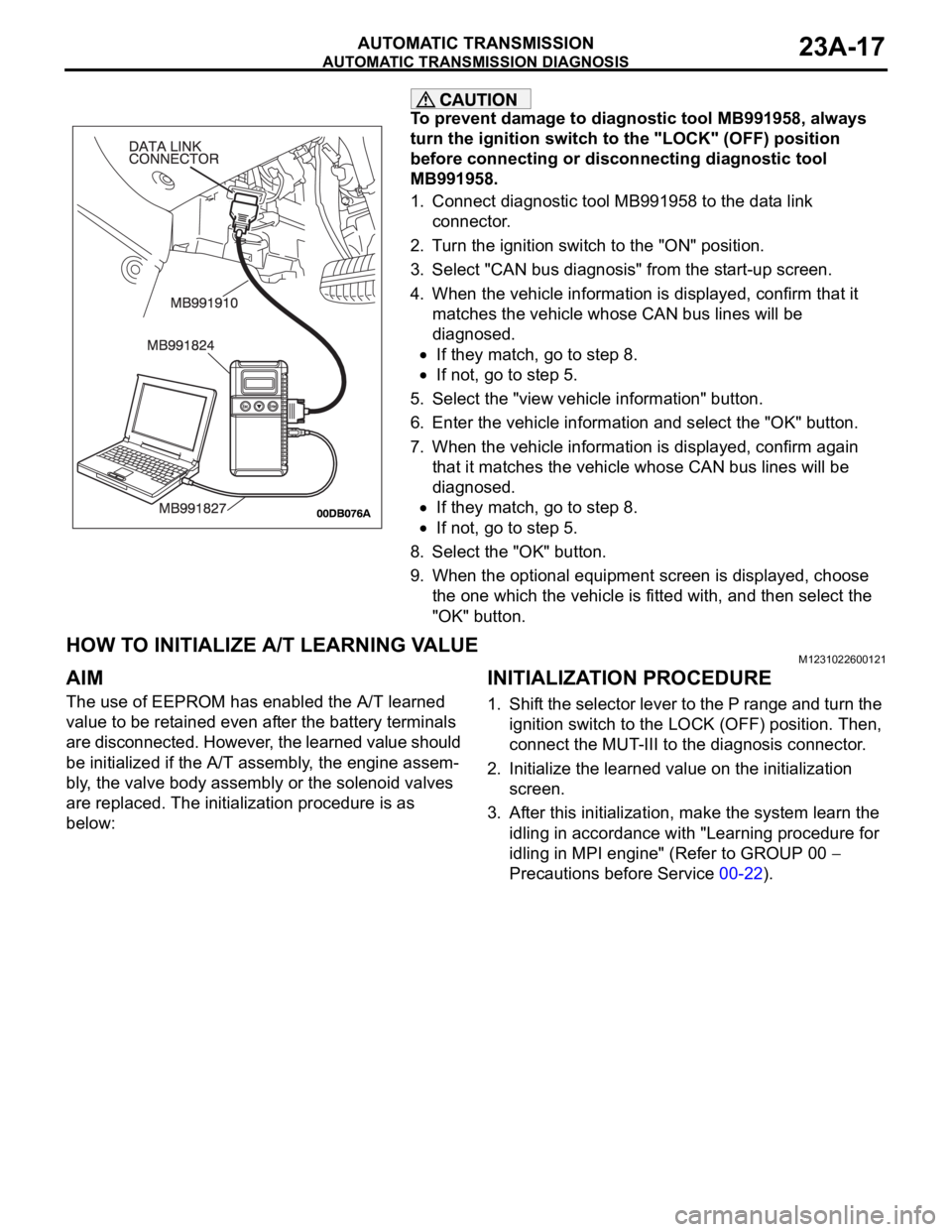
To prevent damage to diagnostic tool MB991958, always
turn the ignition switch to the "LOCK" (OFF) position
before connecting or disconnecting diagnostic tool
MB991958.
1. Connect diagnostic tool MB991958 to the data link
connector.
2. Turn the ignition switch to the "ON" position.
3. Select "CAN bus diagnosis" from the start-up screen.
4. When the vehicle information is displayed, confirm that it
matches the vehicle whose CAN bus lines will be
diagnosed.
If they match, go to step 8.
If not, go to step 5.
5. Select the "view vehicle information" button.
6. Enter the vehicle information and select the "OK" button.
7. When the vehicle information is displayed, confirm again
that it matches the vehicle whose CAN bus lines will be
diagnosed.
If they match, go to step 8.
If not, go to step 5.
8. Select the "OK" button.
9. When the optional equipment screen is displayed, choose
the one which the vehicle is fitted with, and then select the
"OK" button.
HOW TO INITIALIZE A/T LEARNING VALUEM1231022600121
AIM
The use of EEPROM has enabled the A/T learned
value to be retained even after the battery terminals
are disconnected. However, the learned value should
be initialized if the A/T assembly, the engine assem-
bly, the valve body assembly or the solenoid valves
are replaced. The initialization procedure is as
below:
INITIALIZATION PROCEDURE
1. Shift the selector lever to the P range and turn the
ignition switch to the LOCK (OFF) position. Then,
connect the MUT-III to the diagnosis connector.
2. Initialize the learned value on the initialization
screen.
3. After this initialization, make the system learn the
idling in accordance with "Learning procedure for
idling in MPI engine" (Refer to GROUP 00
Precautions before Service 00-22).
Page 1478 of 1500

AUTOMATIC TRANSMISSION DIAGNOSIS
AUTOMATIC TRANSMISSION23A-19
ROAD TESTM1231007800407
Check using the following procedures.
STEP CONDITION
BEFORE
TEST/OPERATIONTEST/OPERATION STANDARD INSPECTION
ITEMINSPECTION
PROCEDURE
PA G E
1 Ignition switch:
(LOCK) OFFIgnition switch
(1) ONData list No.8
(1) Control Relay
Voltage [V]A/T Control
relay
output
voltageA/T Control
relay system
(P.23A-207).
2 Ignition switch:
ON
Engine: Stopped
Transmission
range: PTransmission range
(1) P, (2) R, (3) N, (4)
DData list No.34
(1) P, (2) R, (3) N, (4)
DTransmissi
on range
switchTransmission
range switch
system
(P.23A-97,
P.23A-119).
Transmission range
(1) D (1st gear)
(2) Select the sport
mode (1st gear)
(3) Upshift and hold
the selector lever in
that position (2nd
gear)
(4) Downshift and
hold the selector
lever in that position
(1st gear)Data list No.27
(1) OFF, (2) ON, (3)
ON, (4) ON
Data list No.28
(1) OFF, (2) OFF, (3)
ON, (4) OFF
Data list No.29
(1) OFF, (2) OFF, (3)
OFF, (4) ONSelect
switch and
Shift switchShift switch
assembly
system
(P.23A-252).
Brake pedal
(1) Depressed
(2) ReleasedData list No.19
(1) ON
(2) OFFSto pl amp
switchSt o pla mp
switch system
(P.23A-89).
3 Ignition switch:
ST
Engine: StoppedCranking test with
lever in P or N rangeCranking should be
possibleCranking Engine does
not crank
(P.23A-218).
4 Engine warming
upDrive for 15 minutes
or more so that the
transmission fluid
temperature
becomes 70
90CData list No.7
Gradually rises to 70
90CTransmissi
on fluid
temperatur
e sensorTransmission
fluid
temperature
sensor system
(P.23A-36,
P.23A-47).
5 Engine: Idling
Transmission
range: NBrake pedal (Retest)
(1) Depressed
(2) ReleasedData list No.19
(1) ON
(2) OFFSto pl amp
switchSt o pla mp
switch system
(P.23A-89).
Transmission range
(1) N
D
(2) N
RShould be no
abnormal shift
shocks
Time delay when
engaging should be
within 2 secondsMalfunction
when
startingEngine stalls
when moving
selector lever
from N to D or
N to R
(P.23A-227).
Page 1484 of 1500

AUTOMATIC TRANSMISSION DIAGNOSIS
AUTOMATIC TRANSMISSION23A-25
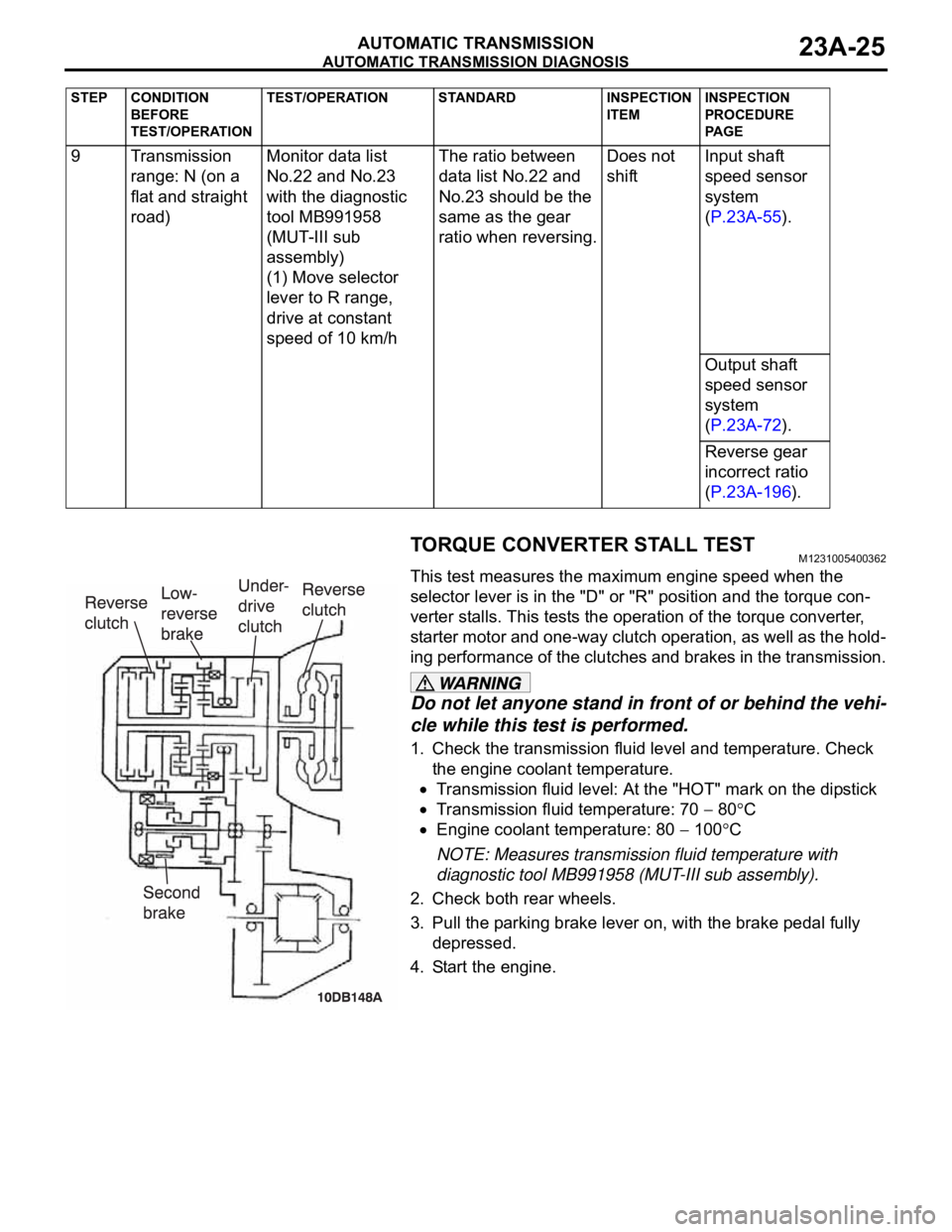
TORQUE CONVERTER STALL TESTM1231005400362
This test measures the maximum engine speed when the
selector lever is in the "D" or "R" position and the torque con-
verter stalls. This tests the operation of the torque converter,
starter motor and one-way clutch operation, as well as the hold-
ing performance of the clutches and brakes in the transmission.
Do not let anyone stand in front of or behind the vehi-
cle while this test is performed.
1. Check the transmission fluid level and temperature. Check
the engine coolant temperature.
Transmission fluid level: At the "HOT" mark on the dipstick
Transmission fluid temperature: 70 80C
Engine coolant temperature: 80 100C
NOTE: Measures transmission fluid temperature with
diagnostic tool MB991958 (MUT-III sub assembly).
2. Check both rear wheels.
3. Pull the parking brake lever on, with the brake pedal fully
depressed.
4. Start the engine. 9 Transmission
range: N (on a
flat and straight
road)Monitor data list
No.22 and No.23
with the diagnostic
tool MB991958
(MUT-III sub
assembly)
(1) Move selector
lever to R range,
drive at constant
speed of 10 km/hThe ratio between
data list No.22 and
No.23 should be the
same as the gear
ratio when reversing.Does not
shiftInput shaft
speed sensor
system
(P.23A-55).
Output shaft
speed sensor
system
(P.23A-72).
Reverse gear
incorrect ratio
(P.23A-196).
STEP CONDITION
BEFORE
TEST/OPERATIONTEST/OPERATION STANDARD INSPECTION
ITEMINSPECTION
PROCEDURE
PA G E
Page 1494 of 1500

AUTOMATIC TRANSMISSION DIAGNOSIS
AUTOMATIC TRANSMISSION23A-35
SYMPTOM CHART M1231008000277
During diagnosis, a DTC code associated with
other system may be set when the ignition switch
is turned on with connector(s) disconnected. On
completion, confirm all systems for DTC code(s).
If DTC code(s) are set, erase them all.
SYMPTOM INSPECTION
PROCEDURE NO.REFERENCE
PA G E
Communication with diagnostic
tool is not possibleCommunication with all systems
is impossible- Group 13B
Symptom
Procedures
13A-539.
Communication with the
A/T-ECU only is impossible- Group 13B
Symptom
Procedures
13A-541.
Driving impossible Engine does not start 1
P.23A-218
Does not move forward 2
P.23A-220
Does not move backward 3
P.23A-223
Does not move (forward and
backward)4
P.23A-226
Malfunction when moving
selector into gearEngine stalls when moving
selector lever from "N" to "D" or
"N" to "R"5
P.23A-227
Shift shock when shifting from
"N" to "D" and long delay6
P.23A-229
Shift shock when shifting from
"N" to "R" and long delay 7
P.23A-232
Shift shock when shifting from
"N" to "D" and "N" to "R" and
long delay 8
P.23A-235
Malfunction when shifting Shift shock and slipping 9
P.23A-236
Does not shift properly Early or late shifting in all gears 10
P.23A-239
Early or late shifting in some
gears11
P.23A-242
Does not shift No diagnostic trouble codes 12
P.23A-244
Malfunction while driving Poor acceleration 13
P.23A-248
Vibration 14
P.23A-250
Shift switch assembly system 15
P.23A-252
Shift position indicator light system
P.23A-269
Page 1495 of 1500

AUTOMATIC TRANSMISSION DIAGNOSIS
AUTOMATIC TRANSMISSION23A-36
DIAGNOSTIC TROUBLE CODE PROCEDURES
(P0713): Transmission Fluid Temperature Sensor System (Open Circuit)
.
CIRCUIT OPERATION
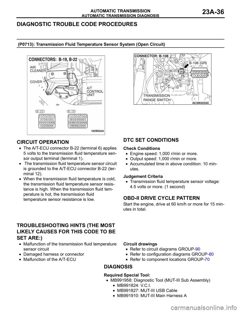
The A/T-ECU connector B-22 (terminal 6) applies
5 volts to the transmission fluid temperature sen-
sor output terminal (terminal 1).
The transmission fluid temperature sensor circuit
is grounded to the A/T-ECU connector B-22 (ter-
minal 12).
When the transmission fluid temperature is cold,
the transmission fluid temperature sensor resis-
tance is high. When the transmission fluid tem-
perature is hot, the transmission fluid
temperature sensor resistance is low.
.
DTC SET CONDITIONS
Check Conditions
Engine speed: 1,000 r/min or more.
Output speed: 1,000 r/min or more.
Accumulated time in above condition: 10 min-
utes.
Judgement Criteria
Transmission fluid temperature sensor voltage:
4.5 volts or more. (1 second)
.
OBD-II DRIVE CYCLE PATTERN
Start the engine, drive at 60 km/h or more for 15 min-
utes in total.
.
TROUBLESHOOTING HINTS (THE MOST
LIKELY CAUSES FOR THIS CODE TO BE
SET ARE:)
Malfunction of the transmission fluid temperature
sensor circuit
Damaged harness or connector
Malfunction of the A/T-ECUCircuit drawings
Refer to circuit diagrams GROUP-90
Refer to configuration diagrams GROUP-80
Refer to component locations GROUP-70
DIAGNOSIS
Required Special Tool:
MB991958: Diagnostic Tool (MUT-III Sub Assembly)
MB991824: V.C.I.
MB991827: MUT-III USB Cable
MB991910: MUT-III Main Harness A