Start system MITSUBISHI 380 2005 Service Manual
[x] Cancel search | Manufacturer: MITSUBISHI, Model Year: 2005, Model line: 380, Model: MITSUBISHI 380 2005Pages: 1500, PDF Size: 47.87 MB
Page 1173 of 1500
BASIC BRAKE SYSTEM DIAGNOSIS
BASIC BRAKE SYSTEM35A-8
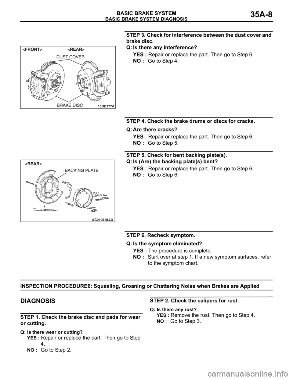
STEP 3. Check for interference between the dust cover and
brake disc.
Q: Is there any interference?
YES : Repair or replace the part. Then go to Step 6.
NO : Go to Step 4.
STEP 4. Check the brake drums or discs for cracks.
Q: Are there cracks?
YES : Repair or replace the part. Then go to Step 6.
NO : Go to Step 5.
STEP 5. Check for bent backing plate(s).
Q: Is (Are) the backing plate(s) bent?
YES : Repair or replace the part. Then go to Step 6.
NO : Go to Step 6.
STEP 6. Recheck symptom.
Q: Is the symptom eliminated?
YES : The procedure is complete.
NO : Start over at step 1. If a new symptom surfaces, refer
to the symptom chart.
INSPECTION PROCEDURE6: Squealing, Groaning or Chattering Noise when Brakes are Applied
.
DIAGNOSIS
STEP 1. Check the brake disc and pads for wear
or cutting.
Q: Is there wear or cutting?
YES :
Repair or replace the part. Then go to Step
4.
NO : Go to Step 2.
STEP 2. Check the calipers for rust.
Q: Is there any rust?
YES :
Remove the rust. Then go to Step 4.
NO : Go to Step 3.
Page 1174 of 1500
BASIC BRAKE SYSTEM DIAGNOSIS
BASIC BRAKE SYSTEM35A-9
STEP 3. Adjust the brake pedal or brake booster
pushrod.
Refer to P.35A-13 or P.35A-26.
Q: Are the brake pedal and the brake booster pushrod
adjusted correctly?
YES :
Go to Step 4.
NO : Adjust the brake pedal or the brake booster
pushrod. Then go to Step 4.
STEP 4. Recheck symptom.
Q: Is the symptom eliminated?
YES :
The procedure is complete.
NO : Start over at step 1. If a new symptom
surfaces, refer to the symptom chart.
INSPECTION PROCEDURE 7: Squealing Noise when Brakes are not Applied
DIAGNOSIS
.
STEP 1. Check whether the backing plate is bent or loose
and interfering with the drum.
Q: Is there a fault?
YES : Replace the part. Then go to Step 10.
NO : Go to Step 2.
STEP 2. Check whether the drum is damaged due to
interference with the backing plate or shoe.
Q: Is there any damage?
YES : Replace the part. Then go to Step 10.
NO : Go to Step 3.
STEP 3. Check the brake drum for wear and the shoe
spring for damage.
Q: Is there any wear or damage?
YES : Replace the part. Then go to Step 10.
NO : Go to Step 4.
STEP 4. Check the brake discs for rust.
Q: Are the brake discs rusted?
YES : Remove the rust by using sand paper. If still rusted,
turn the rotors with an on-the-car brake lathe. Then go
to Step 10.
NO : Go to Step 5.
STEP 5. Check the brake pads for correct installation.
Q: Are the pads installed incorrectly?
YES : Repair the pads. Then go to Step 10.
NO : Go to Step 6.
STEP 6. Check the calipers for correct installation.
Q: Are the calipers installed incorrectly?
YES : Repair the calipers. Then go to Step 10.
NO : Go to Step 7.
Page 1175 of 1500
BASIC BRAKE SYSTEM DIAGNOSIS
BASIC BRAKE SYSTEM35A-10
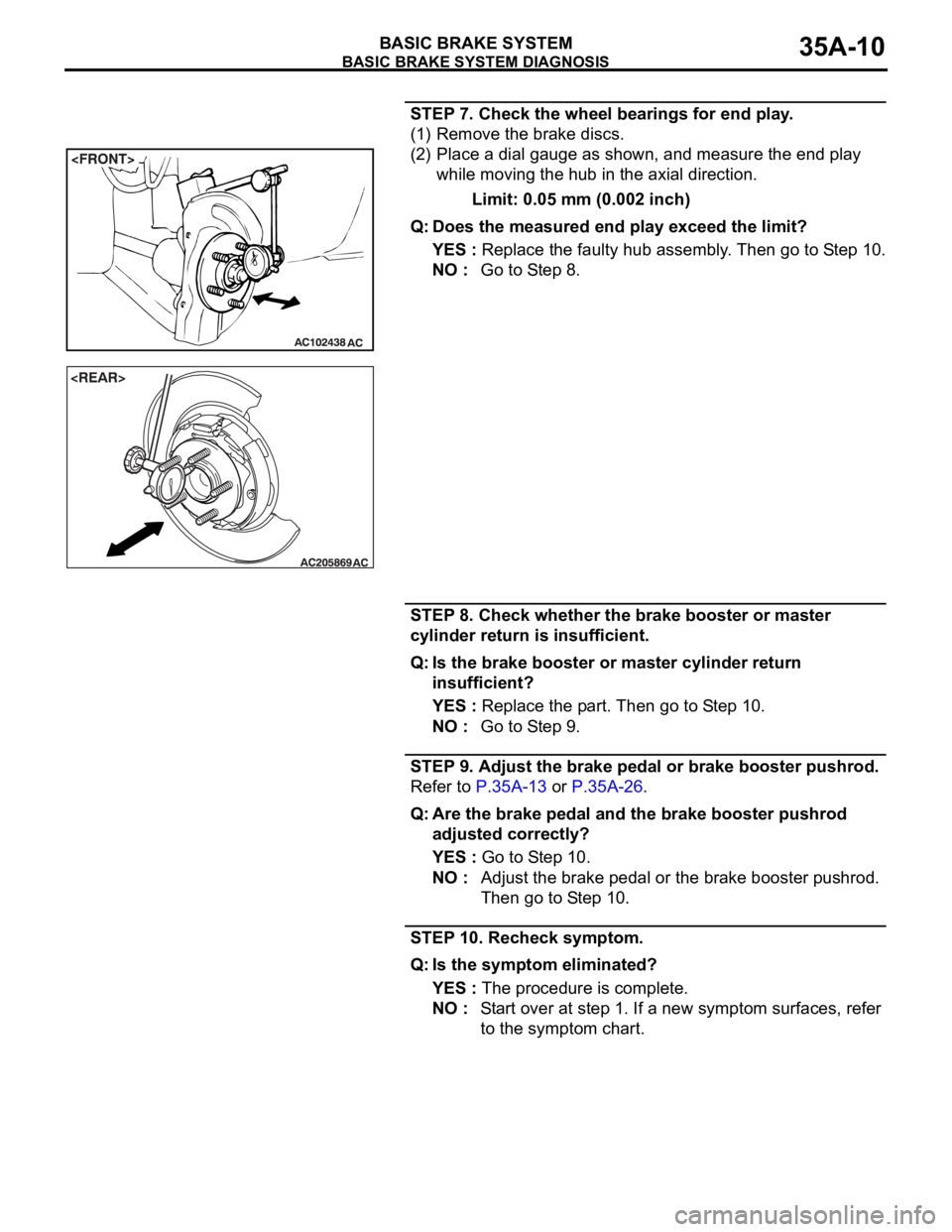
STEP 7. Check the wheel bearings for end play.
(1) Remove the brake discs.
(2) Place a dial gauge as shown, and measure the end play
while moving the hub in the axial direction.
Limit: 0.05 mm (0.002 inch)
Q: Does the measured end play exceed the limit?
YES : Replace the faulty hub assembly. Then go to Step 10.
NO : Go to Step 8.
STEP 8. Check whether the brake booster or master
cylinder return is insufficient.
Q: Is the brake booster or master cylinder return
insufficient?
YES : Replace the part. Then go to Step 10.
NO : Go to Step 9.
STEP 9. Adjust the brake pedal or brake booster pushrod.
Refer to P.35A-13 or P.35A-26.
Q: Are the brake pedal and the brake booster pushrod
adjusted correctly?
YES : Go to Step 10.
NO : Adjust the brake pedal or the brake booster pushrod.
Then go to Step 10.
STEP 10. Recheck symptom.
Q: Is the symptom eliminated?
YES : The procedure is complete.
NO : Start over at step 1. If a new symptom surfaces, refer
to the symptom chart.
Page 1177 of 1500
SPECIAL TOOLS
BASIC BRAKE SYSTEM35A-12
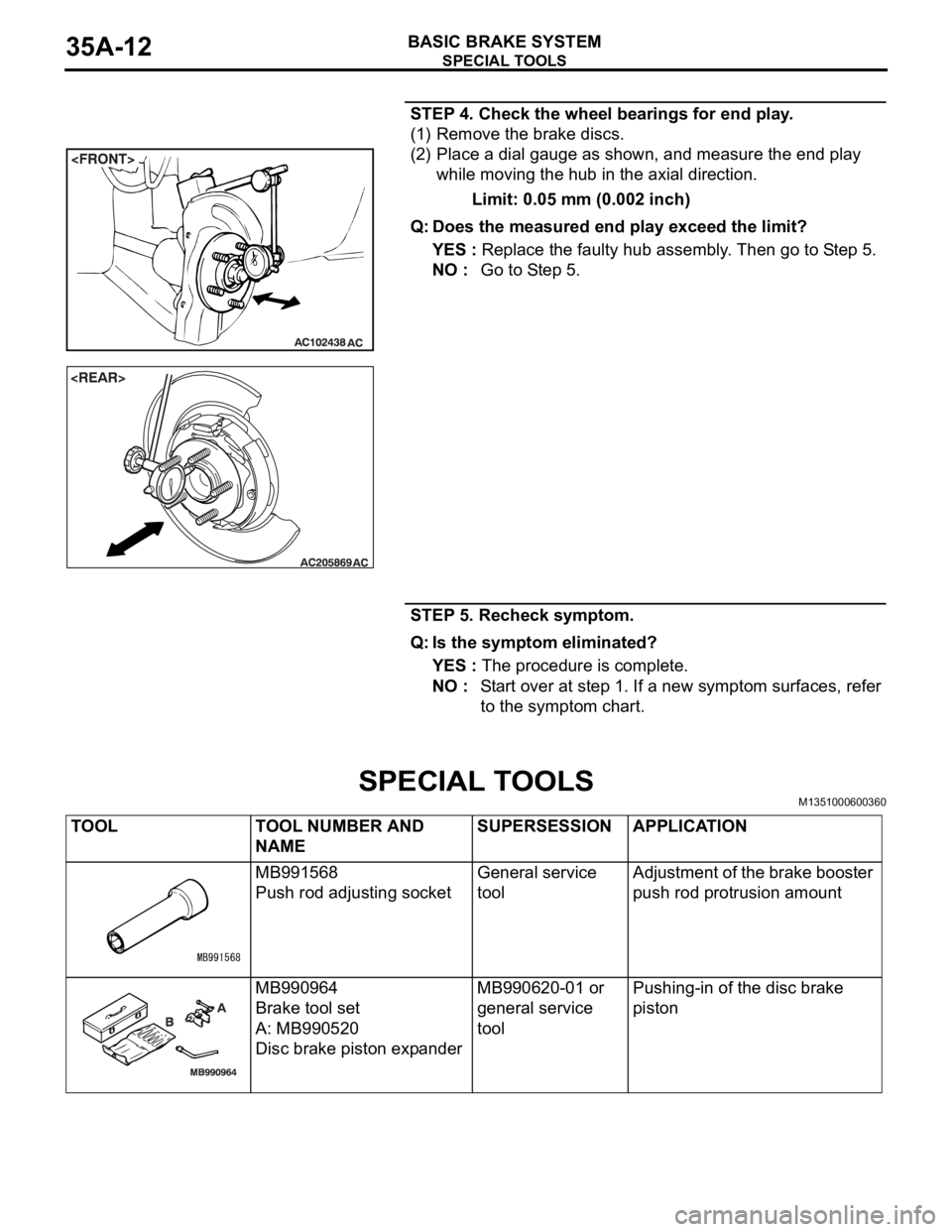
STEP 4. Check the wheel bearings for end play.
(1) Remove the brake discs.
(2) Place a dial gauge as shown, and measure the end play
while moving the hub in the axial direction.
Limit: 0.05 mm (0.002 inch)
Q: Does the measured end play exceed the limit?
YES : Replace the faulty hub assembly. Then go to Step 5.
NO : Go to Step 5.
STEP 5. Recheck symptom.
Q: Is the symptom eliminated?
YES : The procedure is complete.
NO : Start over at step 1. If a new symptom surfaces, refer
to the symptom chart.
SPECIAL TOOLSM1351000600360
TOOL TOOL NUMBER AND
NAMESUPERSESSION APPLICATION
MB991568
Push rod adjusting socketGeneral service
toolAdjustment of the brake booster
push rod protrusion amount
MB990964
Brake tool set
A: MB990520
Disc brake piston expanderMB990620-01 or
general service
toolPushing-in of the disc brake
piston
Page 1179 of 1500
ON-VEHICLE SERVICE
BASIC BRAKE SYSTEM35A-14
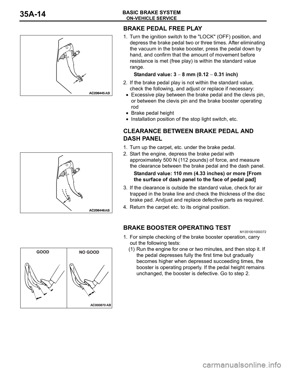
BRAKE PEDAL FREE PLAY
1. Turn the ignition switch to the "LOCK" (OFF) position, and
depress the brake pedal two or three times. After eliminating
the vacuum in the brake booster, press the pedal down by
hand, and confirm that the amount of movement before
resistance is met (free play) is within the standard value
range.
Standard value: 3
8 mm (0.12 0.31 inch)
2. If the brake pedal play is not within the standard value,
check the following, and adjust or replace if necessary:
Excessive play between the brake pedal and the clevis pin,
or between the clevis pin and the brake booster operating
rod
Brake pedal height
Installation position of the stop light switch, etc.
CLEARANCE BETWEEN BRAKE PEDAL AND
DASH PANEL
1. Turn up the carpet, etc. under the brake pedal.
2. Start the engine, depress the brake pedal with
approximately 500 N (112 pounds) of force, and measure
the clearance between the brake pedal and the dash panel.
Standard value: 110 mm (4.33 inches) or more [From
the surface of dash panel to the face of pedal pad]
3. If the clearance is outside the standard value, check for air
trapped in the brake line and check the thickness of the disc
brake pad. Andjust and replace defective parts as required.
4. Return the carpet etc. to its original position.
BRAKE BOOSTER OPERATING TESTM1351001000372
1. For simple checking of the brake booster operation, carry
out the following tests:
(1) Run the engine for one or two minutes, and then stop it. If
the pedal depresses fully the first time but gradually
becomes higher when depressed succeeding times, the
booster is operating properly. If the pedal height remains
unchanged, the booster is defective. Go to step 2.
Page 1180 of 1500
ON-VEHICLE SERVICE
BASIC BRAKE SYSTEM35A-15
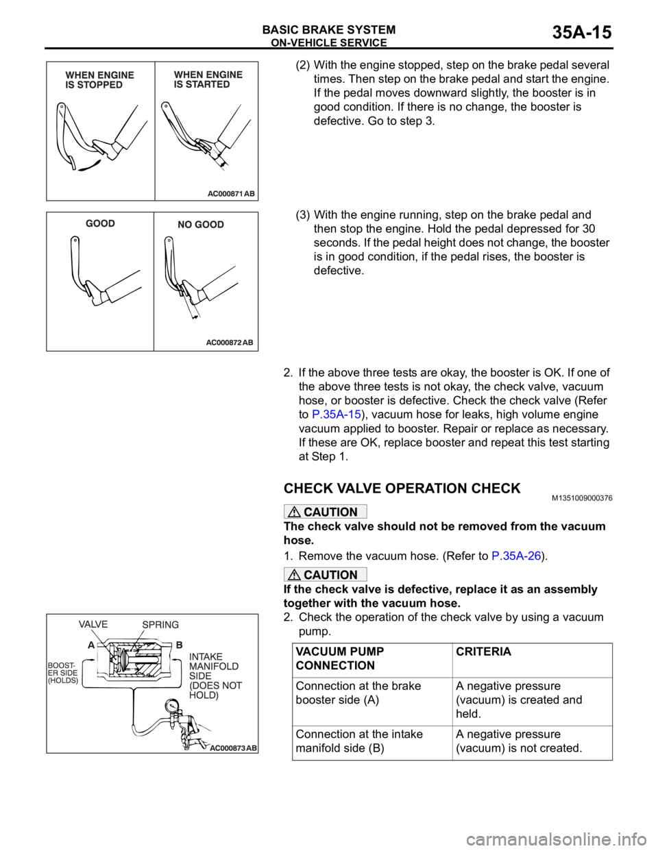
(2) With the engine stopped, step on the brake pedal several
times. Then step on the brake pedal and start the engine.
If the pedal moves downward slightly, the booster is in
good condition. If there is no change, the booster is
defective. Go to step 3.
(3) With the engine running, step on the brake pedal and
then stop the engine. Hold the pedal depressed for 30
seconds. If the pedal height does not change, the booster
is in good condition, if the pedal rises, the booster is
defective.
2. If the above three tests are okay, the booster is OK. If one of
the above three tests is not okay, the check valve, vacuum
hose, or booster is defective. Check the check valve (Refer
to P.35A-15), vacuum hose for leaks, high volume engine
vacuum applied to booster. Repair or replace as necessary.
If these are OK, replace booster and repeat this test starting
at Step 1.
CHECK VALVE OPERATION CHECKM1351009000376
The check valve should not be removed from the vacuum
hose.
1. Remove the vacuum hose. (Refer to P.35A-26).
If the check valve is defective, replace it as an assembly
together with the vacuum hose.
2. Check the operation of the check valve by using a vacuum
pump.
VACUUM PUMP
CONNECTIONCRITERIA
Connection at the brake
booster side (A)A negative pressure
(vacuum) is created and
held.
Connection at the intake
manifold side (B)A negative pressure
(vacuum) is not created.
Page 1181 of 1500
ON-VEHICLE SERVICE
BASIC BRAKE SYSTEM35A-16
BLEEDINGM1351001400455
Use only brake fluid DOT 3 or DOT 4. Never mix the speci-
fied brake fluid with other fluid as it will influence the brak-
ing performance significantly.
.
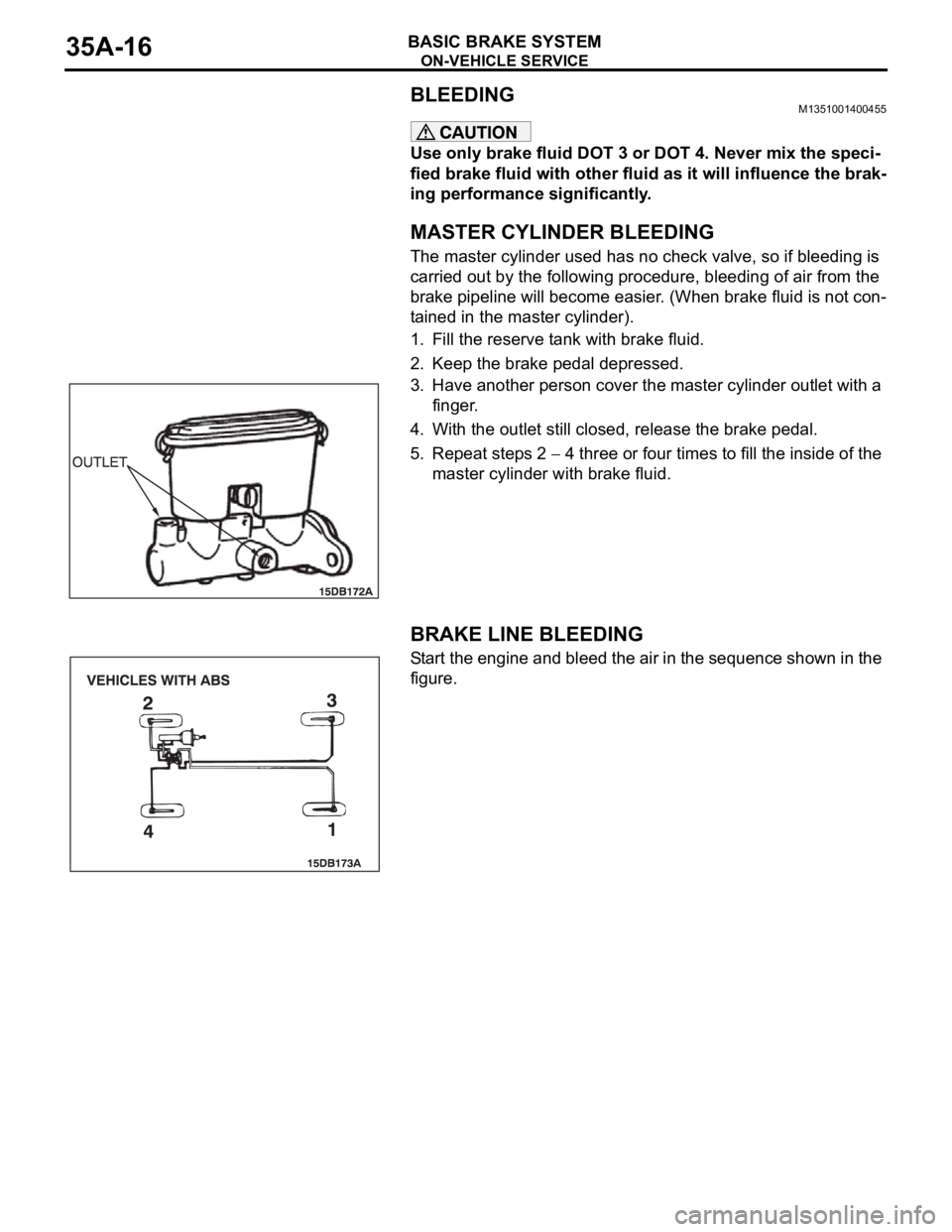
MASTER CYLINDER BLEEDING
The master cylinder used has no check valve, so if bleeding is
carried out by the following procedure, bleeding of air from the
brake pipeline will become easier. (When brake fluid is not con-
tained in the master cylinder).
1. Fill the reserve tank with brake fluid.
2. Keep the brake pedal depressed.
3. Have another person cover the master cylinder outlet with a
finger.
4. With the outlet still closed, release the brake pedal.
5. Repeat steps 2
4 three or four times to fill the inside of the
master cylinder with brake fluid.
.
BRAKE LINE BLEEDING
Start the engine and bleed the air in the sequence shown in the
figure.
Page 1196 of 1500
DISC BRAKE ASSEMBLY
BASIC BRAKE SYSTEM35A-31
INSTALLATION SERVICE POINT
.
>>A<< BRAKE DRAG FORCE CHECK
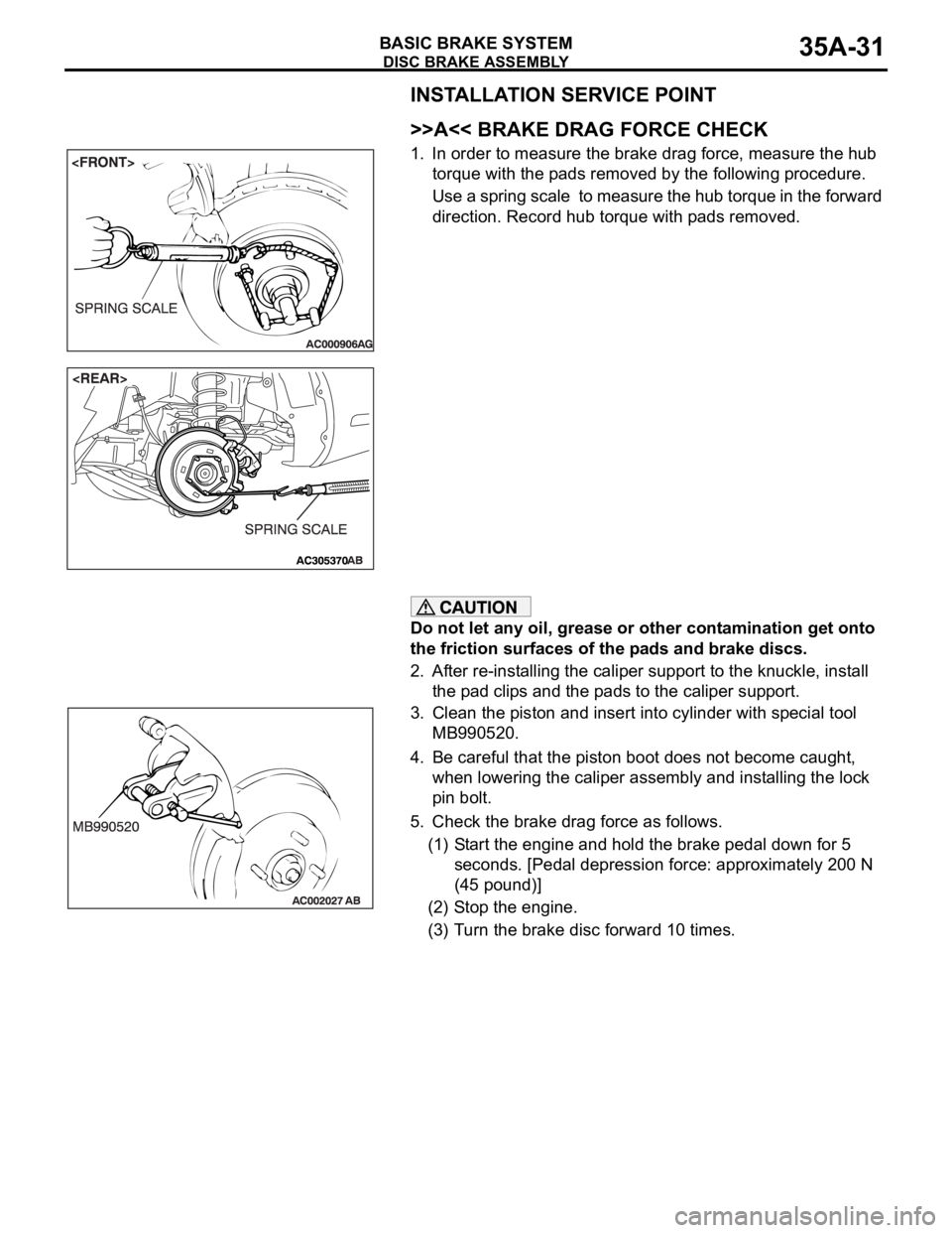
1. In order to measure the brake drag force, measure the hub
torque with the pads removed by the following procedure.
Use a spring scale to measure the hub torque in the forward
direction. Record hub torque with pads removed.
Do not let any oil, grease or other contamination get onto
the friction surfaces of the pads and brake discs.
2. After re-installing the caliper support to the knuckle, install
the pad clips and the pads to the caliper support.
3. Clean the piston and insert into cylinder with special tool
MB990520.
4. Be careful that the piston boot does not become caught,
when lowering the caliper assembly and installing the lock
pin bolt.
5. Check the brake drag force as follows.
(1) Start the engine and hold the brake pedal down for 5
seconds. [Pedal depression force: approximately 200 N
(45 pound)]
(2) Stop the engine.
(3) Turn the brake disc forward 10 times.
Page 1224 of 1500

HOW TO USE THIS MANUAL
GENERAL00-3
HOW TO USE THIS MANUALM1001000100897
MAINTENANCE, REPAIR AND
SERVICING EXPLANATIONS
This manual provides explanations, etc. concerning
procedures for the inspection, maintenance, repair
and servicing of the subject model. Unless otherwise
specified, each service procedure covers all models.
Procedures covering specific models are identified
by the model codes, or similar designation (engine
type, transaxle type, etc). A description of these des-
ignations is covered in this manual under "VEHICLE
IDENTIFICATION."
.
ON-VEHICLE SERVICE
The "ON-VEHICLE SERVICE" section has proce-
dures for performing inspections and adjustments of
particularly important components. These proce-
dures are done with regard to maintenance and ser-
vicing, but other inspections (looseness, play,
cracking, damage, etc.) must also be performed.
.
SERVICE PROCEDURES
The service steps are arranged in numerical order.
Attention to be paid in performing vehicle service are
described in detail in SERVICE POINTS.
DEFINITION OF TERMS
.
STANDARD VALUE
Indicates the value used as the standard for judging
whether or not a part or adjustment is correct.
.
LIMIT
Shows the maximum or minimum value for judging
whether or not a part or adjustment is acceptable.
.
REFERENCE VALUE
Indicates the adjustment value prior to starting the
work (presented in order to facilitate assembly and
adjustment procedures, and so they can be com-
pleted in a shorter time).
.
DANGER, WARNING, AND CAUTION
DANGER, WARNING, and CAUTION call special
attention to a necessary action or to an action that
must be avoided. The differences among DANGER,
WARNING, and CAUTION are as follows:
If a DANGER is not followed, the result is severe
bodily harm or even death.
If a WARNING is not followed, the result could be
bodily injury.
If a CAUTION is not followed, the result could be
damage to the vehicle, vehicle components or
service equipment.
TIGHTENING TORQUE INDICATION
The tightening torque indicates a median and its tol-
erance by a unit of N
m (in-lb.) or Nm (ft.-lb.). For
fasteners with no assigned torque value, refer to
P.00-32.
SPECIAL TOOL NOTE
Only MMC special tool part numbers are called out in
the repair sections of this manual. Please refer to the
special tool cross-reference chart located at the
beginning of each group, for the special tool number
that is available in your market.
ABBREVIATIONS
The following abbreviations are used in this manual
for classification of model types:
A/T:Automatic transaxle, or models equipped with
automatic transaxle.
MPI: Multipoint fuel injection, or engines equipped
with multiport fuel injection.
A/C: Air conditioning.
3.8L engine: 3.8 litre <6G75> engine, or a model
equipped with such an engine.
ABS: Anti-lock Braking System
TCL: Traction Control System
ECU: Electronic Control Unit
V.C.I.: Vehicle Communication Interface
SWS: Simplified Wiring System
CAN: Controller Area Network
M/T: Manual Transmission
SRS: Supplemental Restraint System
Page 1227 of 1500

TROUBLESHOOTING GUIDELINES
GENERAL00-6
TROUBLESHOOTING GUIDELINESM1001008800340
VERIFY THE COMPLAINT
Make sure the customer's complaint and the ser-
vice writer's work order description are under-
stood before starting work.
Make sure you understand the correct operation
of the system. Read the service manual descrip-
tion to verify normal system operation.
Operate the system to see the symptoms. Look
for other symptoms that were not reported by the
customer, or on the work order, that may be
related to the problem.
DETERMINE POSSIBLE CAUSES
Compare the confirmed symptoms to the diagnostic
symptom indexes to find the right diagnosis proce-
dure.
If the confirmed symptoms cannot be found on any
symptom index, determine other possible causes.
Analyze the system diagrams and list all possible
causes for the problem symptoms.
Rank all these possible causes in order of proba-
bility, based on how much of the system they
cover, how likely they are to be the cause, and
how easy they will be to check. Be sure to take
experience into account. Consider the causes of
similar problems seen in the past. The list of
causes should be ranked in order from general to
specific, from most-likely to least-likely, and from
easy-to-check to hard-to-check.
FIND THE PROBLEM
After the symptoms have been confirmed, and prob-
able causes have been identified, the next step is to
make step-by-step checks of the suspected system
components, junctions, and links in logical order.
Use the diagnostic procedures in the service manual
whenever possible. Follow these procedures care-
fully to avoid missing an important step in the diagno-
sis sequence. It might be the skipped step that leads
to the solution of the problem.
If the service manual doesn't have step-by-step pro-
cedures to help diagnose the problem, make a series
of checks based on the ranked list of probable
causes. Troubleshooting checks should be made in
the order that the list of causes was ranked:
general to specific
most-likely to least-likely
easy-to-check to hard-to-check
REPAIR THE PROBLEM
When the step-by-step troubleshooting checks find a
fault, perform the proper repairs. Make sure to fix the
root cause of the problem, not just the symptom. Just
fixing the symptom, without fixing the root cause, will
cause the symptom to eventually return.
VERIFY THE REPAIR
After repairs are made, recheck the operation of the
system to confirm that the problem is eliminated. Be
sure to check the system thoroughly. Sometimes
new problems are revealed after repairs have been
made.