relay MITSUBISHI 380 2005 Owner's Guide
[x] Cancel search | Manufacturer: MITSUBISHI, Model Year: 2005, Model line: 380, Model: MITSUBISHI 380 2005Pages: 1500, PDF Size: 47.87 MB
Page 199 of 1500
SYMPTOM PROCEDURES
SIMPLIFIED WIRING SYSTEM (SWS)54B-199
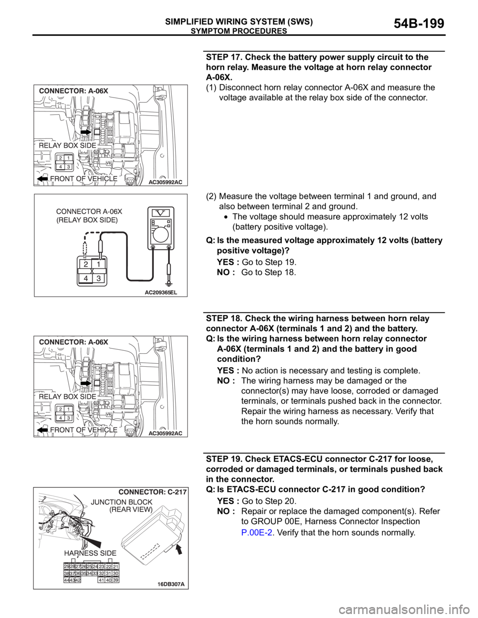
STEP 17. Check the battery power supply circuit to the
horn relay. Measure the voltage at horn relay connector
A-06X.
(1) Disconnect horn relay connector A-06X and measure the
voltage available at the relay box side of the connector.
(2) Measure the voltage between terminal 1 and ground, and
also between terminal 2 and ground.
The voltage should measure approximately 12 volts
(battery positive voltage).
Q: Is the measured voltage approximately 12 volts (battery
positive voltage)?
YES : Go to Step 19.
NO : Go to Step 18.
STEP 18. Check the wiring harness between horn relay
connector A-06X (terminals 1 and 2) and the battery.
Q: Is the wiring harness between horn relay connector
A-06X (terminals 1 and 2) and the battery in good
condition?
YES : No action is necessary and testing is complete.
NO : The wiring harness may be damaged or the
connector(s) may have loose, corroded or damaged
terminals, or terminals pushed back in the connector.
Repair the wiring harness as necessary. Verify that
the horn sounds normally.
STEP 19. Check ETACS-ECU connector C-217 for loose,
corroded or damaged terminals, or terminals pushed back
in the connector.
Q: Is ETACS-ECU connector C-217 in good condition?
YES : Go to Step 20.
NO : Repair or replace the damaged component(s). Refer
to GROUP 00E, Harness Connector Inspection
P.00E-2. Verify that the horn sounds normally.
Page 200 of 1500
SYMPTOM PROCEDURES
SIMPLIFIED WIRING SYSTEM (SWS)54B-200
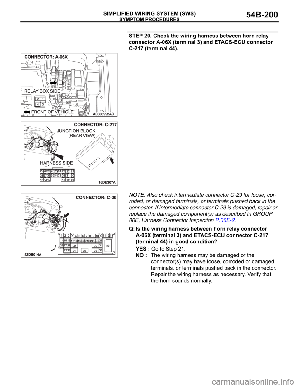
STEP 20. Check the wiring harness between horn relay
connector A-06X (terminal 3) and ETACS-ECU connector
C-217 (terminal 44).
NOTE: Also check intermediate connector C-29 for loose, cor-
roded, or damaged terminals, or terminals pushed back in the
connector. If intermediate connector C-29 is damaged, repair or
replace the damaged component(s) as described in GROUP
00E, Harness Connector Inspection P.00E-2.
Q: Is the wiring harness between horn relay connector
A-06X (terminal 3) and ETACS-ECU connector C-217
(terminal 44) in good condition?
YES : Go to Step 21.
NO : The wiring harness may be damaged or the
connector(s) may have loose, corroded or damaged
terminals, or terminals pushed back in the connector.
Repair the wiring harness as necessary. Verify that
the horn sounds normally.
Page 201 of 1500
SYMPTOM PROCEDURES
SIMPLIFIED WIRING SYSTEM (SWS)54B-201
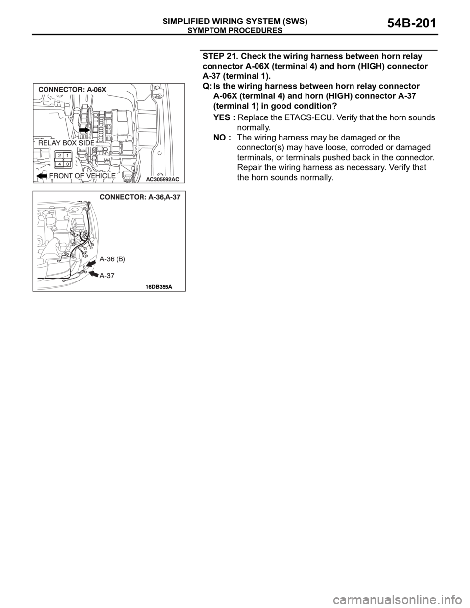
STEP 21. Check the wiring harness between horn relay
connector A-06X (terminal 4) and horn (HIGH) connector
A-37 (terminal 1).
Q: Is the wiring harness between horn relay connector
A-06X (terminal 4) and horn (HIGH) connector A-37
(terminal 1) in good condition?
YES : Replace the ETACS-ECU. Verify that the horn sounds
normally.
NO : The wiring harness may be damaged or the
connector(s) may have loose, corroded or damaged
terminals, or terminals pushed back in the connector.
Repair the wiring harness as necessary. Verify that
the horn sounds normally.
Page 224 of 1500
SYMPTOM PROCEDURES
SIMPLIFIED WIRING SYSTEM (SWS)54B-224
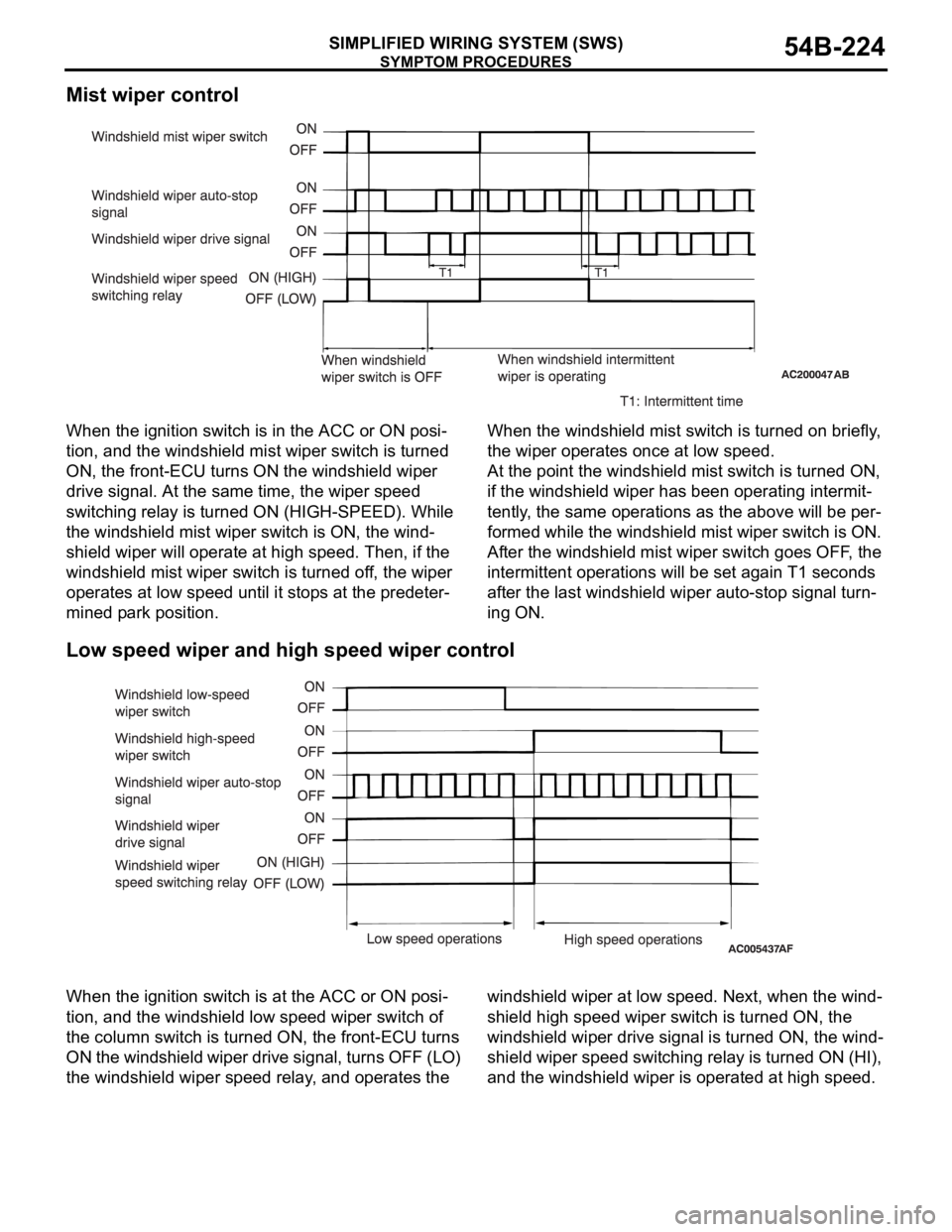
Mist wiper control
When the ignition switch is in the ACC or ON posi-
tion, and the windshield mist wiper switch is turned
ON, the front-ECU turns ON the windshield wiper
drive signal. At the same time, the wiper speed
switching relay is turned ON (HIGH-SPEED). While
the windshield mist wiper switch is ON, the wind-
shield wiper will operate at high speed. Then, if the
windshield mist wiper switch is turned off, the wiper
operates at low speed until it stops at the predeter-
mined park position.When the windshield mist switch is turned on briefly,
the wiper operates once at low speed.
At the point the windshield mist switch is turned ON,
if the windshield wiper has been operating intermit-
tently, the same operations as the above will be per-
formed while the windshield mist wiper switch is ON.
After the windshield mist wiper switch goes OFF, the
intermittent operations will be set again T1 seconds
after the last windshield wiper auto-stop signal turn-
ing ON.
.
Low speed wiper and high speed wiper control
When the ignition switch is at the ACC or ON posi-
tion, and the windshield low speed wiper switch of
the column switch is turned ON, the front-ECU turns
ON the windshield wiper drive signal, turns OFF (LO)
the windshield wiper speed relay, and operates the windshield wiper at low speed. Next, when the wind-
shield high speed wiper switch is turned ON, the
windshield wiper drive signal is turned ON, the wind-
shield wiper speed switching relay is turned ON (HI),
and the windshield wiper is operated at high speed.
.
Page 225 of 1500
SYMPTOM PROCEDURES
SIMPLIFIED WIRING SYSTEM (SWS)54B-225
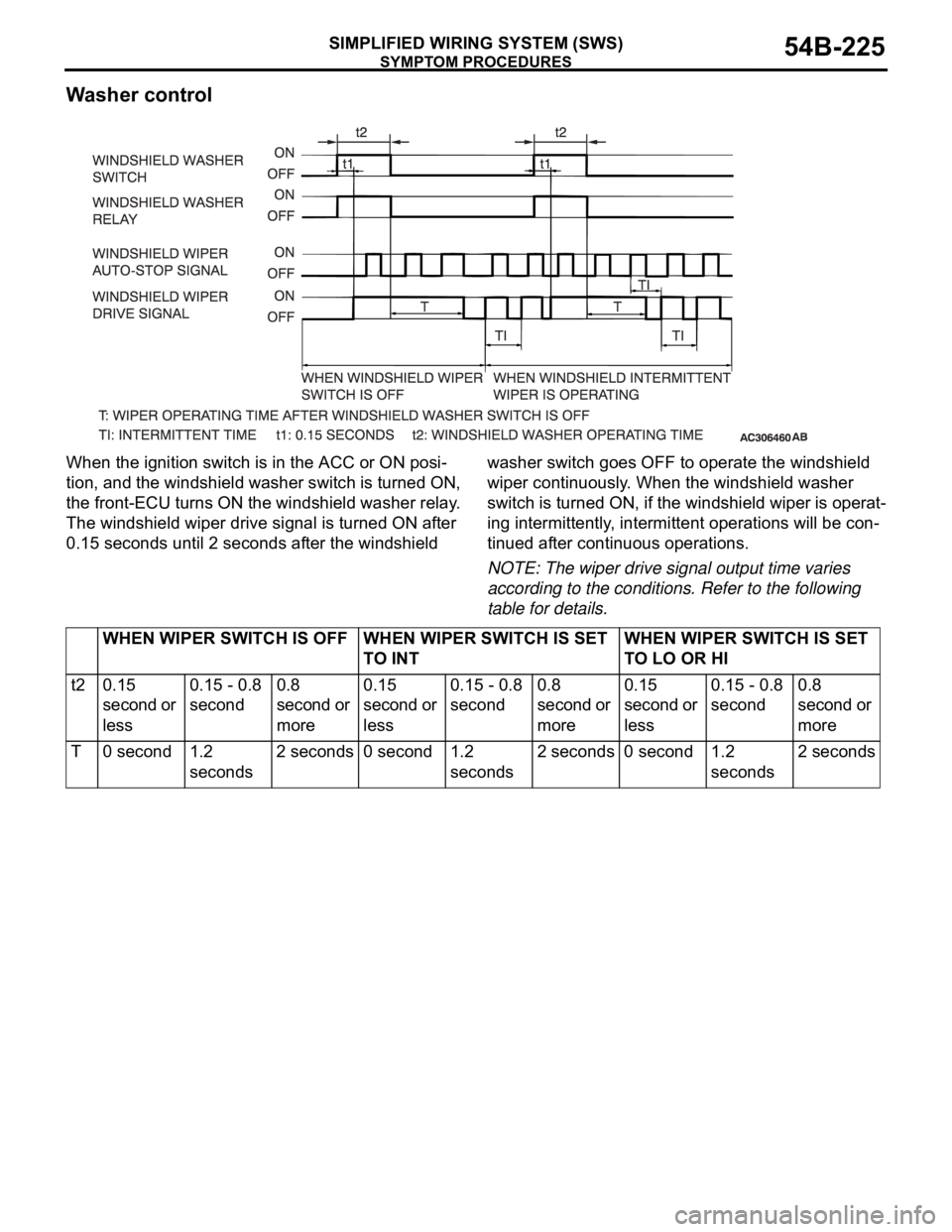
Washer control
When the ignition switch is in the ACC or ON posi-
tion, and the windshield washer switch is turned ON,
the front-ECU turns ON the windshield washer relay.
The windshield wiper drive signal is turned ON after
0.15 seconds until 2 seconds after the windshield washer switch goes OFF to operate the windshield
wiper continuously. When the windshield washer
switch is turned ON, if the windshield wiper is operat-
ing intermittently, intermittent operations will be con-
tinued after continuous operations.
NOTE: The wiper drive signal output time varies
according to the conditions. Refer to the following
table for details.
WHEN WIPER SWITCH IS OFF WHEN WIPER SWITCH IS SET
TO INTWHEN WIPER SWITCH IS SET
TO LO OR HI
t2 0.15
second or
less0.15 - 0.8
second0.8
second or
more0.15
second or
less0.15 - 0.8
second0.8
second or
more0.15
second or
less0.15 - 0.8
second0.8
second or
more
T0 second1.2
seconds2 seconds 0 second 1.2
seconds2 seconds 0 second 1.2
seconds2 seconds
Page 226 of 1500
SYMPTOM PROCEDURES
SIMPLIFIED WIRING SYSTEM (SWS)54B-226
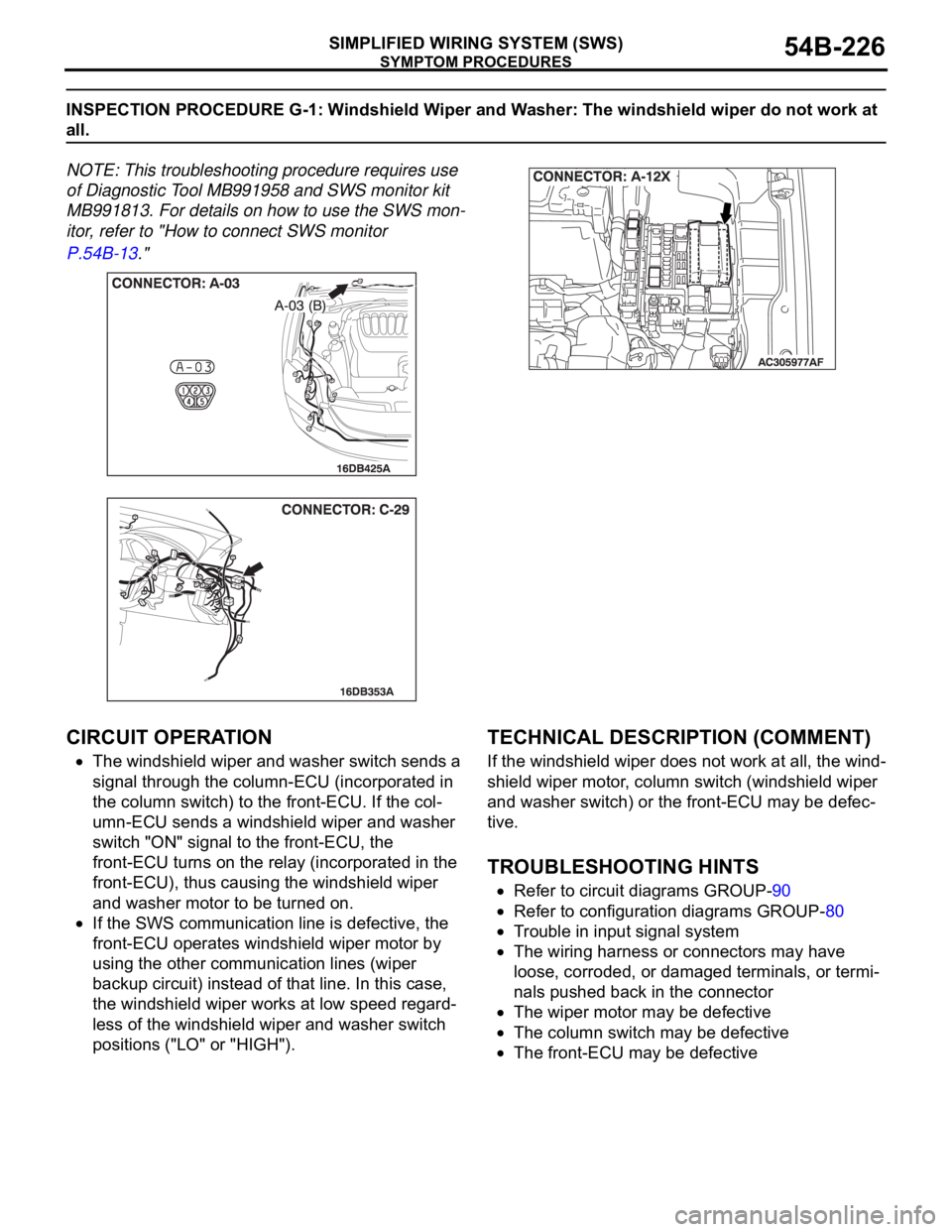
INSPECTION PROCEDURE G-1: Windshield Wiper and Washer: The windshield wiper do not work at
all.
NOTE: This troubleshooting procedure requires use
of Diagnostic Tool MB991958 and SWS monitor kit
MB991813. For details on how to use the SWS mon-
itor, refer to "How to connect SWS monitor
P.54B-13."
.
CIRCUIT OPERATION
The windshield wiper and washer switch sends a
signal through the column-ECU (incorporated in
the column switch) to the front-ECU. If the col-
umn-ECU sends a windshield wiper and washer
switch "ON" signal to the front-ECU, the
front-ECU turns on the relay (incorporated in the
front-ECU), thus causing the windshield wiper
and washer motor to be turned on.
If the SWS communication line is defective, the
front-ECU operates windshield wiper motor by
using the other communication lines (wiper
backup circuit) instead of that line. In this case,
the windshield wiper works at low speed regard-
less of the windshield wiper and washer switch
positions ("LO" or "HIGH").
.
TECHNICAL DESCRIPTION (COMMENT)
If the windshield wiper does not work at all, the wind-
shield wiper motor, column switch (windshield wiper
and washer switch) or the front-ECU may be defec-
tive.
.
TROUBLESHOOTING HINTS
Refer to circuit diagrams GROUP-90
Refer to configuration diagrams GROUP-80
Trouble in input signal system
The wiring harness or connectors may have
loose, corroded, or damaged terminals, or termi-
nals pushed back in the connector
The wiper motor may be defective
The column switch may be defective
The front-ECU may be defective
Page 232 of 1500
SYMPTOM PROCEDURES
SIMPLIFIED WIRING SYSTEM (SWS)54B-232
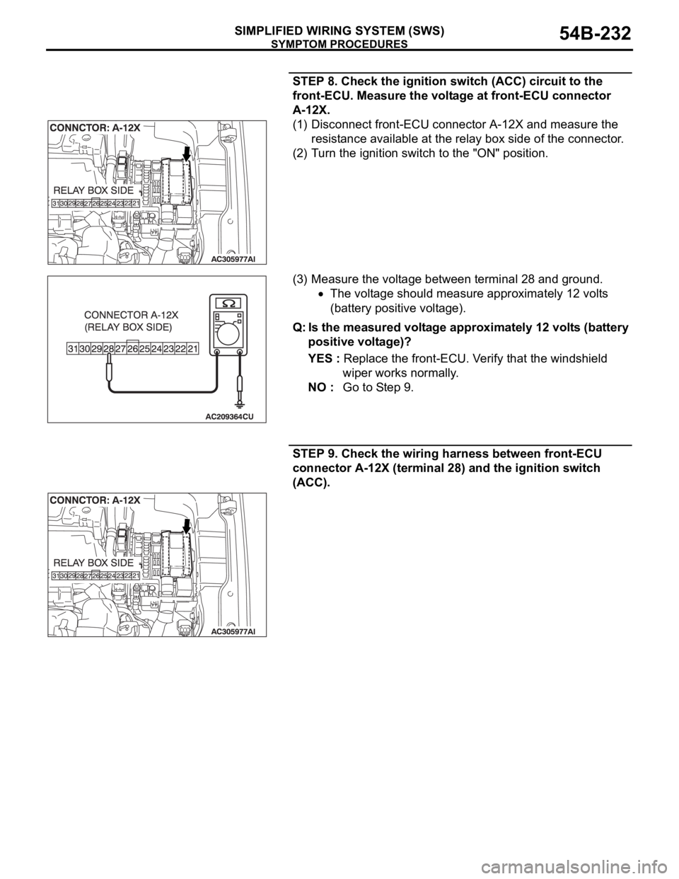
STEP 8. Check the ignition switch (ACC) circuit to the
front-ECU. Measure the voltage at front-ECU connector
A-12X.
(1) Disconnect front-ECU connector A-12X and measure the
resistance available at the relay box side of the connector.
(2) Turn the ignition switch to the "ON" position.
(3) Measure the voltage between terminal 28 and ground.
The voltage should measure approximately 12 volts
(battery positive voltage).
Q: Is the measured voltage approximately 12 volts (battery
positive voltage)?
YES : Replace the front-ECU. Verify that the windshield
wiper works normally.
NO : Go to Step 9.
STEP 9. Check the wiring harness between front-ECU
connector A-12X (terminal 28) and the ignition switch
(ACC).
Page 251 of 1500
SYMPTOM PROCEDURES
SIMPLIFIED WIRING SYSTEM (SWS)54B-251
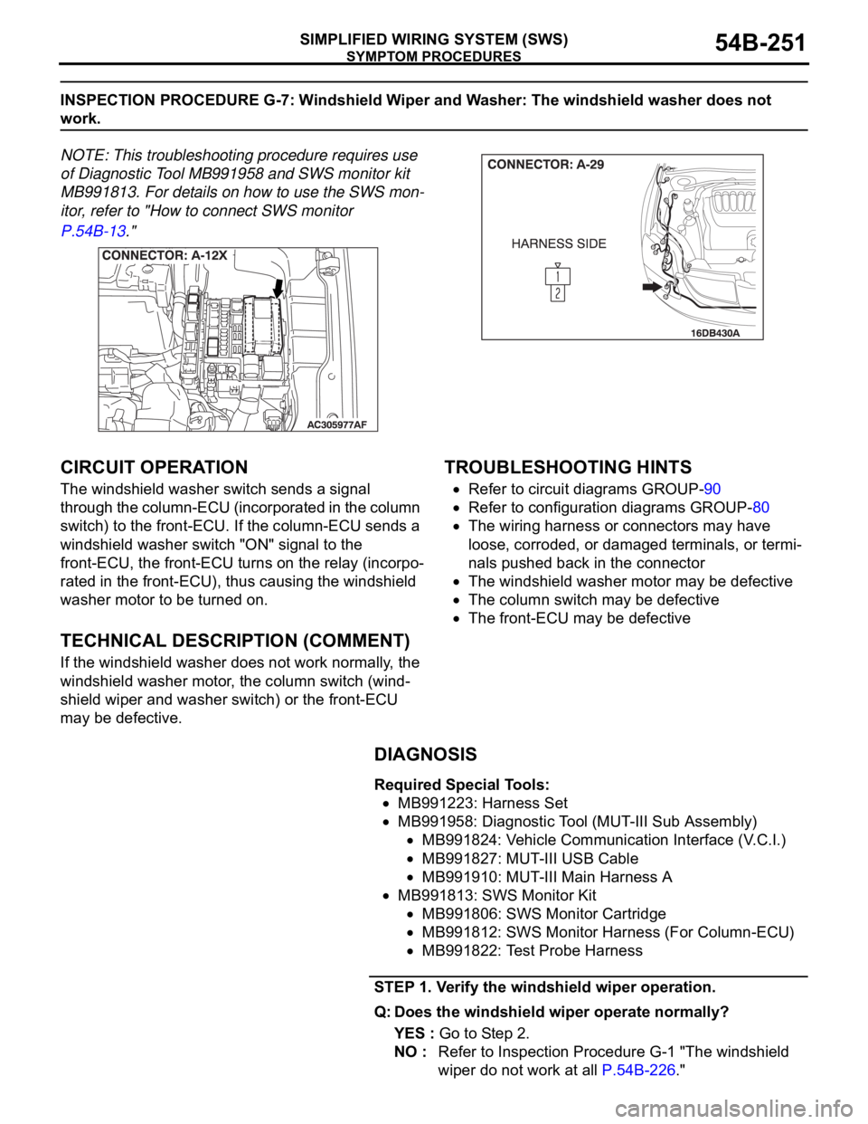
INSPECTION PROCEDURE G-7: Windshield Wiper and Washer: The windshield washer does not
work.
NOTE: This troubleshooting procedure requires use
of Diagnostic Tool MB991958 and SWS monitor kit
MB991813. For details on how to use the SWS mon-
itor, refer to "How to connect SWS monitor
P.54B-13."
.
CIRCUIT OPERATION
The windshield washer switch sends a signal
through the column-ECU (incorporated in the column
switch) to the front-ECU. If the column-ECU sends a
windshield washer switch "ON" signal to the
front-ECU, the front-ECU turns on the relay (incorpo-
rated in the front-ECU), thus causing the windshield
washer motor to be turned on.
.
TECHNICAL DESCRIPTION (COMMENT)
If the windshield washer does not work normally, the
windshield washer motor, the column switch (wind-
shield wiper and washer switch) or the front-ECU
may be defective.
.
TROUBLESHOOTING HINTS
Refer to circuit diagrams GROUP-90
Refer to configuration diagrams GROUP-80
The wiring harness or connectors may have
loose, corroded, or damaged terminals, or termi-
nals pushed back in the connector
The windshield washer motor may be defective
The column switch may be defective
The front-ECU may be defective
DIAGNOSIS
Required Special Tools:
MB991223: Harness Set
MB991958: Diagnostic Tool (MUT-III Sub Assembly)
MB991824: Vehicle Communication Interface (V.C.I.)
MB991827: MUT-III USB Cable
MB991910: MUT-III Main Harness A
MB991813: SWS Monitor Kit
MB991806: SWS Monitor Cartridge
MB991812: SWS Monitor Harness (For Column-ECU)
MB991822: Test Probe Harness
STEP 1. Verify the windshield wiper operation.
Q: Does the windshield wiper operate normally?
YES : Go to Step 2.
NO : Refer to Inspection Procedure G-1 "The windshield
wiper do not work at all P.54B-226."
Page 258 of 1500
SYMPTOM PROCEDURES
SIMPLIFIED WIRING SYSTEM (SWS)54B-258
Taillamps and headlamps illumination
.
Taillamps
If the column switch sends a taillamp switch "ON" signal to the
front-ECU, the front-ECU turns on its taillamp relay, causing the
taillamps to illuminate.
NOTE: This description covers the taillamps only. In actual driv-
ing, the taillamps may be turned off due to the headlamp auto-
matic shut-off function. For the details of the headlamp
automatic shut-off function, refer to .
.
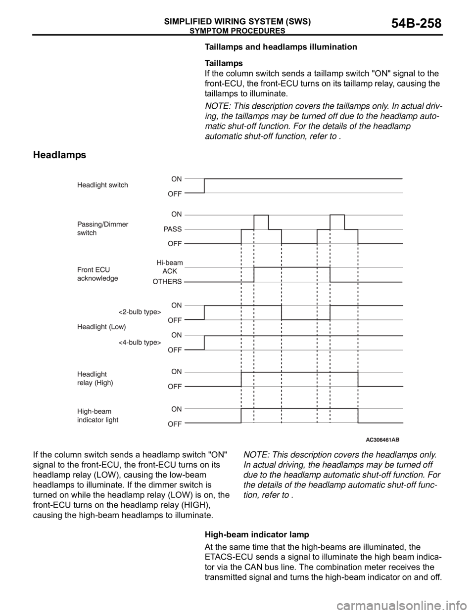
Headlamps
If the column switch sends a headlamp switch "ON"
signal to the front-ECU, the front-ECU turns on its
headlamp relay (LOW), causing the low-beam
headlamps to illuminate. If the dimmer switch is
turned on while the headlamp relay (LOW) is on, the
front-ECU turns on the headlamp relay (HIGH),
causing the high-beam headlamps to illuminate.NOTE: This description covers the headlamps only.
In actual driving, the headlamps may be turned off
due to the headlamp automatic shut-off function. For
the details of the headlamp automatic shut-off func-
tion, refer to .
High-beam indicator lamp
At the same time that the high-beams are illuminated, the
ETACS-ECU sends a signal to illuminate the high beam indica-
tor via the CAN bus line. The combination meter receives the
transmitted signal and turns the high-beam indicator on and off.
Page 260 of 1500
SYMPTOM PROCEDURES
SIMPLIFIED WIRING SYSTEM (SWS)54B-260
INSPECTION PROCEDURE H-1: Headlamp and Taillamp: The taillamps do not illuminate normally.
NOTE: This troubleshooting procedure requires the
use of Diagnostic Tool MB991958 and SWS monitor
kit MB991813. For details on how to connect the
SWS monitor, refer to "How to connect SWS monitor
P.54B-13."
.
CIRCUIT OPERATION
When the lighting switch is set to "TAIL" position, the
"TAIL" signal is sent through the column-ECU (incor-
porated in the column switch) to the front-ECU. If the
front-ECU receives the "TAIL" signal through the col-
umn-ECU, the front-ECU turns on the taillamp relay
(incorporated in the front-ECU), thus causing the
taillamps to illuminate.
.
TECHNICAL DESCRIPTION (COMMENT)
If the taillamps do not illuminate normally, the column
switch or the front-ECU may be defective.
.
TROUBLESHOOTING HINTS
Refer to circuit diagrams GROUP-90
Refer to configuration diagrams GROUP-80
Trouble in input signal system
The wiring harness or connectors may have
loose, corroded, or damaged terminals, or termi-
nals pushed back in the connector
The front-ECU may be defective
DIAGNOSIS
Required Special Tools:
MB991223: Harness Set
MB991958: Diagnostic Tool (MUT-III Sub Assembly)
MB991824: Vehicle Communication Interface (V.C.I.)
MB991827: MUT-III USB Cable
MB991910: MUT-III Main Harness A
MB991813: SWS Monitor Kit
MB991806: SWS Monitor Cartridge
MB991812: SWS Monitor Harness (For Column-ECU)
MB991822: Test Probe Harness