Cruis control MITSUBISHI 380 2005 Repair Manual
[x] Cancel search | Manufacturer: MITSUBISHI, Model Year: 2005, Model line: 380, Model: MITSUBISHI 380 2005Pages: 1500, PDF Size: 47.87 MB
Page 1394 of 1500
AUTO-CRUISE CONTROL
ENGINE AND EMISSION CONTROL17-63
CIRCUIT OPERATION
The Engine ECU detects "CRUISE" (MAIN) switch
"ON" signal to illuminate the "CRUISE" indicator
lamp on the combination meter.
.
COMMENT
Connector(s), wiring harness in the CAN bus line
between the Engine ECU and the combination
meter, power supply to the Engine ECU, the combi-
nation meter, the Engine ECU may be defective.
.
TROUBLESHOOTING HINTS
Malfunction of the combination meter.
Damaged harness or connector.
Malfunction of the Engine ECU.
Circuit drawings
Refer to circuit diagrams GROUP-90
Refer to configuration diagrams GROUP-80
Refer to component locations GROUP-70
DIAGNOSIS
Required Special Tools:
MB991958: Diagnostic Tool (MUT-III Sub Assembly)
MB991824: V.C.I.
MB991827: MUT-III USB Cable
MB991910: MUT-III Main Harness A
STEP 1. Using Diagnostic Tool MB991958, diagnose the
CAN bus line.
To prevent damage to Diagnostic Tool MB991958, always
turn the ignition switch to the "LOCK" (OFF) position
before connecting or disconnecting Diagnostic Tool
MB991958.
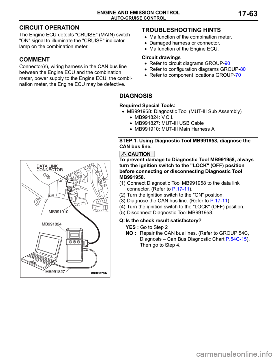
(1) Connect Diagnostic Tool MB991958 to the data link
connector. (Refer to P.17-11).
(2) Turn the ignition switch to the "ON" position.
(3) Diagnose the CAN bus line. (Refer to P.17-11).
(4) Turn the ignition switch to the "LOCK" (OFF) position.
(5) Disconnect Diagnostic Tool MB991958.
Q: Is the check result satisfactory?
YES : Go to Step 2
NO : Repair the CAN bus lines. (Refer to GROUP 54C,
Diagnosis
Can Bus Diagnostic Chart P.54C-15).
Then go to Step 4.
Page 1395 of 1500
AUTO-CRUISE CONTROL
ENGINE AND EMISSION CONTROL17-64
STEP 2. Using Diagnostic Tool MB991958, read the MPI
diagnostic trouble code.
To prevent damage to Diagnostic Tool MB991958, always
turn the ignition switch to the "LOCK" (OFF) position
before connecting or disconnecting Diagnostic Tool
MB991958.
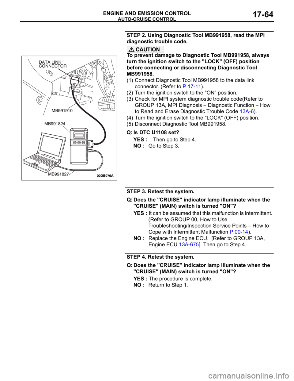
(1) Connect Diagnostic Tool MB991958 to the data link
connector. (Refer to P.17-11).
(2) Turn the ignition switch to the "ON" position.
(3) Check for MPI system diagnostic trouble code(Refer to
GROUP 13A, MPI Diagnosis
Diagnostic Function How
to Read and Erase Diagnostic Trouble Code 13A-6).
(4) Turn the ignition switch to the "LOCK" (OFF) position.
(5) Disconnect Diagnostic Tool MB991958.
Q: Is DTC U1108 set?
YES : . Then go to Step 4.
NO : Go to Step 3.
STEP 3. Retest the system.
Q: Does the "CRUISE" indicator lamp illuminate when the
"CRUISE" (MAIN) switch is turned "ON"?
YES : It can be assumed that this malfunction is intermittent.
(Refer to GROUP 00, How to Use
Troubleshooting/Inspection Service Points
How to
Cope with Intermittent Malfunction P.00-14).
NO : Replace the Engine ECU. [Refer to GROUP 13A,
Engine ECU 13A-675]. Then go to Step 4.
STEP 4. Retest the system.
Q: Does the "CRUISE" indicator lamp illuminate when the
"CRUISE" (MAIN) switch is turned "ON"?
YES : The procedure is complete.
NO : Return to Step 1.
Page 1396 of 1500

AUTO-CRUISE CONTROL
ENGINE AND EMISSION CONTROL17-65
DATA LIST REFERENCE TABLE - Auto Cruise ControlM1172002400471
When shifting the selector lever to "D" range, apply the brakes so that the vehicle does not move
forward.
Driving tests always need two persons: one driver and one observer.
NOTE: *:After the inspection is completed, disconnect the throttle position sensor connector, and then delete
the diagnostic trouble code using use of Diagnostic Tool MB991958. (Refer to P.17-11).
MUT-III
Diagnostic
To o l
DISPLAYITEM
NO.INSPECTION ITEM INSPECTION REQUIREMENT NORMAL
CONDITION
APS
SNS(MAIN)11 A c c e l e r a t o r p e d a l
position sensor (main)Ignition
switch:
"ON"Accelerator pedal: Released
435
1,035 mV
Accelerator pedal: Gradually
depressedIncreases in
response to the
pedal depression
stroke
Accelerator pedal: Fully
depressed4,000 mV or more
BRAKE SW 89 Stoplamp switch Brake pedal: Depressed ON
Brake pedal: Released OFF
CANCEL
CODE57 Cancel code Ignition switch: "ON" The cancel code,
which set when the
auto-cruise control
system was
cancelled at the
last time, is set
again.
CANCEL
SWITCH75 Auto-cruise
control
switchCANCEL "CANCEL" switch: ON ON
"CANCEL" switch: OFF OFF
CLUTCH SW 78 Transmission inhibitor
switchTransmission inhibitor switch: "P" or
"N"ON
Transmission inhibitor switch: Other
than aboveOFF
CRUISE 81 Auto-cruise control
system operationAuto-cruise control system: active ON
Auto-cruise control system: Inactive OFF
MAIN SW 86 Auto-cruise
control
switchCRUISE
(MAIN)"CRUISE" (MAIN) switch: "ON" ON
"CRUISE" (MAIN) switch: "OFF" OFF
RESUME
SWITCH91 Auto-cruise
control
switchACC/RES "ACC/RES" switch: ON ON
"ACC/RES" switch: OFF OFF
SET SWITCH 92 Auto-cruise
control
switchCOAST/S
ET"COAST/SET" switch: ON ON
"COAST/SET" switch: OFF OFF
STOPLIGHT
SW74 Stoplamp switch Brake pedal: Depressed ON
Brake pedal: Released OFF
Page 1397 of 1500

AUTO-CRUISE CONTROL
ENGINE AND EMISSION CONTROL17-66
If the air intake duct is removed from the throttle body take great care to keep fingers away
from the throttle plate. The drive motor has very high torque and is capable of random move-
ment at any time. Do not under any circumstances activate the throttle plate by hand.
When removing the throttle body from the intake manifold disconnect the wiring first. During
replacement connect the wiring last.
Do not activate the throttle body using a DC suppy to test the motor,as permanent damage to
the throttle body will result.
TP
SNSR(MAIN)13 Throttle position sensor
(main)*(1) Accelerator pedal:
Released
(2) Accelerator pedal:
Depressed(1) Throttle
valve fully
closed1035 1250 mV
(2) Throttle
valve fully
open4,000 mV or more
A/C switch: "OFF" to "ON" Voltage rises
Selector lever: "N" to "D" Voltage rises
VSS 04 Vehicle speed signal Road test the vehicle The speedometer
and Diagnostic
Tool MB991958
display the same
value. MUT-III
Diagnostic
To o l
DISPLAYITEM
NO.INSPECTION ITEM INSPECTION REQUIREMENT NORMAL
CONDITION
Page 1398 of 1500
AUTO-CRUISE CONTROL
ENGINE AND EMISSION CONTROL17-67
ENGINE ECU TERMINAL VOLTAGE REFERENCE CHART FOR AUTO-CRUISE
CONTROL SYSTEM OPERATION
M1172004800055
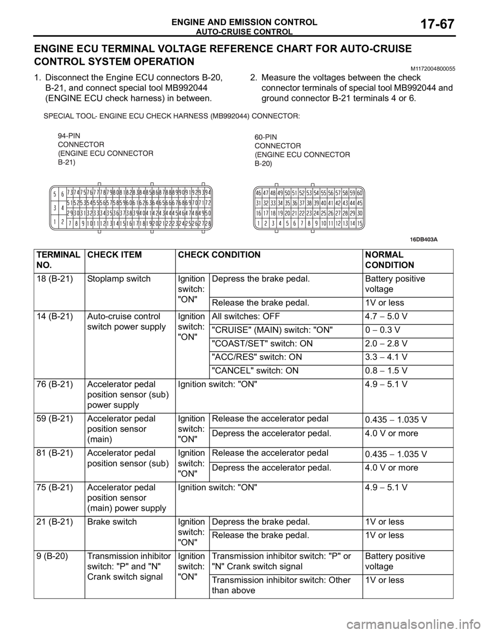
1. Disconnect the Engine ECU connectors B-20,
B-21, and connect special tool MB992044
(ENGINE ECU check harness) in between.2. Measure the voltages between the check
connector terminals of special tool MB992044 and
ground connector B-21 terminals 4 or 6.
TERMINAL
NO.CHECK ITEM CHECK CONDITION NORMAL
CONDITION
18 (B-21) Stoplamp switch Ignition
switch:
"ON"Depress the brake pedal. Battery positive
voltage
Release the brake pedal. 1V or less
14 (B-21) Auto-cruise control
switch power supplyIgnition
switch:
"ON"All switches: OFF 4.7
5.0 V
"CRUISE" (MAIN) switch: "ON" 0
0.3 V
"COAST/SET" switch: ON 2.0
2.8 V
"ACC/RES" switch: ON 3.3
4.1 V
"CANCEL" switch: ON 0.8
1.5 V
76 (B-21) Accelerator pedal
position sensor (sub)
power supplyIgnition switch: "ON" 4.9
5.1 V
59 (B-21) Accelerator pedal
position sensor
(main)Ignition
switch:
"ON"Release the accelerator pedal
0.435
1.035 V
Depress the accelerator pedal. 4.0 V or more
81 (B-21) Accelerator pedal
position sensor (sub)Ignition
switch:
"ON"Release the accelerator pedal
0.435
1.035 V
Depress the accelerator pedal. 4.0 V or more
75 (B-21) Accelerator pedal
position sensor
(main) power supplyIgnition switch: "ON" 4.9
5.1 V
21 (B-21) Brake switch Ignition
switch:
"ON"Depress the brake pedal. 1V or less
Release the brake pedal. 1V or less
9 (B-20) Transmission inhibitor
switch: "P" and "N"
Crank switch signalIgnition
switch:
"ON"Transmission inhibitor switch: "P" or
"N" Crank switch signalBattery positive
voltage
Transmission inhibitor switch: Other
than above1V or less
Page 1399 of 1500

AUTO-CRUISE CONTROL
ENGINE AND EMISSION CONTROL17-68
If the air intake duct is removed from the throttle body take great care to keep fingers away
from the throttle plate. The drive motor has very high torque and is capable of random move-
ment at any time. Do not under any circumstances activate the throttle plate by hand.
When removing the throttle body from the intake manifold disconnect the wiring first. During
replacement connect the wiring last.
Do not activate the throttle body using a DC suppy to test the motor,as permanent damage to
the throttle body will result.
10 (B-20) Throttle position
sensor power supplyIgnition switch: "ON" 4.9 5.1 V
57 (B-20) Throttle position
sensor (sub)(1) Accelerator pedal:
Released
(2) Accelerator pedal:
Depressed(1) Throttle
valve fully
closed1035
1250 mV
(2) Throttle
valve fully open4000 mV or more
42 (B-20) Throttle position
sensor (main)(1) Accelerator pedal:
Released
(2) Accelerator pedal:
Depressed(1) Throttle
valve fully
closed1035
1250 mV
(2) Throttle
valve fully open4000 mV or more
49 (B-20) Throttle actuator
control motor (
)
Ignition switch: "ON"
Accelerator pedal: fully closed to fully
openedDecreases slightly
(approx. 2 V) from
battery voltage.
50 (B-20) Throttle actuator
control motor (+)
Ignition switch: "ON"
Accelerator pedal: fully opened to fully
closedDecreases slightly
(approx. 2 V) from
battery voltage. TERMINAL
NO.CHECK ITEM CHECK CONDITION NORMAL
CONDITION
Page 1400 of 1500
AUTO-CRUISE CONTROL
ENGINE AND EMISSION CONTROL17-69
SPECIAL TOOLSM1172000600509
TOOL TOOL NUMBER AND
NAMESUPERSESSION APPLICATION
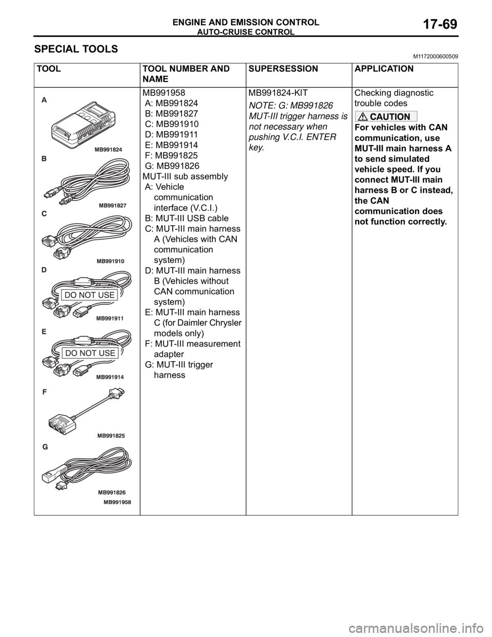
MB991958
A: MB991824
B: MB991827
C: MB991910
D: MB991911
E: MB991914
F: MB991825
G: MB991826
MUT-III sub assembly
A: Vehicle
communication
interface (V.C.I.)
B: MUT-III USB cable
C: MUT-III main harness
A (Vehicles with CAN
communication
system)
D: MUT-III main harness
B (Vehicles without
CAN communication
system)
E: MUT-III main harness
C (for Daimler Chrysler
models only)
F: MUT-III measurement
adapter
G: MUT-III trigger
harnessMB991824-KIT
NOTE: G: MB991826
MUT-III trigger harness is
not necessary when
pushing V.C.I. ENTER
key.Checking diagnostic
trouble codes
For vehicles with CAN
communication, use
MUT-III main harness A
to send simulated
vehicle speed. If you
connect MUT-III main
harness B or C instead,
the CAN
communication does
not function correctly.
Page 1401 of 1500

AUTO-CRUISE CONTROL
ENGINE AND EMISSION CONTROL17-70
MB991223
A: MB991219
B: MB991220
C: MB991221
D: MB991222
Harness set
A: Inspection harness
B: LED harness
C: LED harness adapter
D: ProbeGeneral service tools Checking the continuity
and measuring the
voltage at the harness
connector
MB992044
Engine ECU check
harness
Measuring the terminal
voltage at the Engine
ECU
MB992045
Auto Trans. ECU check
harness
Measuring the terminal
voltage at the Auto Trans.
ECU TOOL TOOL NUMBER AND
NAMESUPERSESSION APPLICATION
Page 1402 of 1500
AUTO-CRUISE CONTROL
ENGINE AND EMISSION CONTROL17-71
ON-VEHICLE SERVICE
AUTO-CRUISE CONTROL SWITCH CHECKM1172001200054
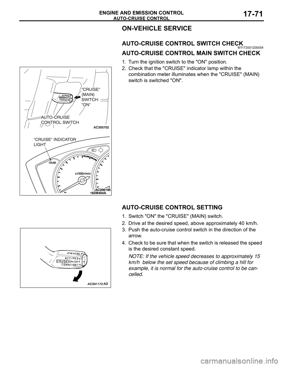
AUTO-CRUISE CONTROL MAIN SWITCH CHECK
1. Turn the ignition switch to the "ON" position.
2. Check that the "CRUISE" indicator lamp within the
combination meter illuminates when the "CRUISE" (MAIN)
switch is switched "ON".
AUTO-CRUISE CONTROL SETTING
1. Switch "ON" the "CRUISE" (MAIN) switch.
2. Drive at the desired speed, above approximately 40 km/h.
3. Push the auto-cruise control switch in the direction of the
arrow.
4. Check to be sure that when the switch is released the speed
is the desired constant speed.
NOTE: If the vehicle speed decreases to approximately 15
km/h below the set speed because of climbing a hill for
example, it is normal for the auto-cruise control to be can-
celled.
Page 1403 of 1500
AUTO-CRUISE CONTROL
ENGINE AND EMISSION CONTROL17-72
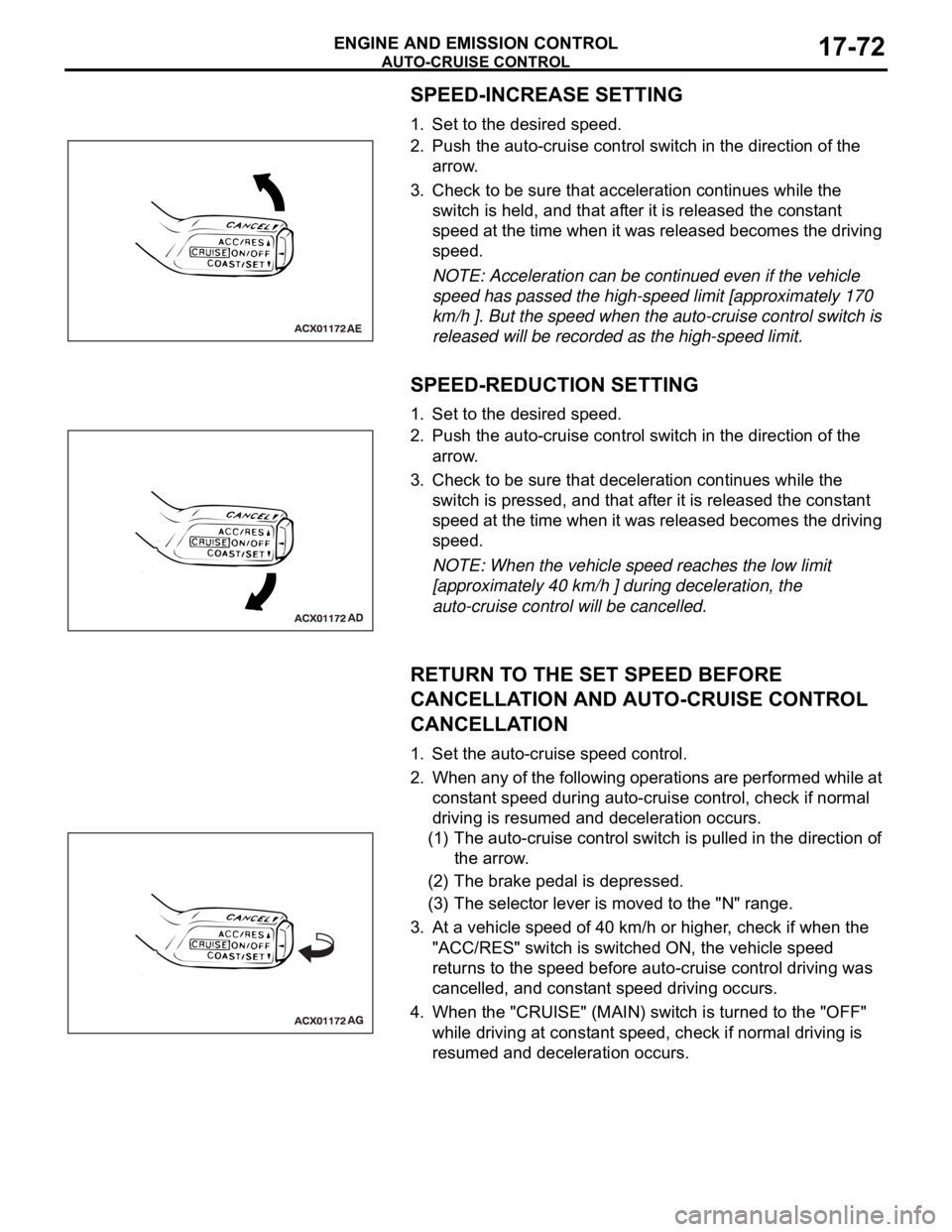
SPEED-INCREASE SETTING
1. Set to the desired speed.
2. Push the auto-cruise control switch in the direction of the
arrow.
3. Check to be sure that acceleration continues while the
switch is held, and that after it is released the constant
speed at the time when it was released becomes the driving
speed.
NOTE: Acceleration can be continued even if the vehicle
speed has passed the high-speed limit [approximately 170
km/h ]. But the speed when the auto-cruise control switch is
released will be recorded as the high-speed limit.
SPEED-REDUCTION SETTING
1. Set to the desired speed.
2. Push the auto-cruise control switch in the direction of the
arrow.
3. Check to be sure that deceleration continues while the
switch is pressed, and that after it is released the constant
speed at the time when it was released becomes the driving
speed.
NOTE: When the vehicle speed reaches the low limit
[approximately 40 km/h ] during deceleration, the
auto-cruise control will be cancelled.
RETURN TO THE SET SPEED BEFORE
CANCELLATION AND AUTO-CRUISE CONTROL
CANCELLATION
1. Set the auto-cruise speed control.
2. When any of the following operations are performed while at
constant speed during auto-cruise control, check if normal
driving is resumed and deceleration occurs.
(1) The auto-cruise control switch is pulled in the direction of
the arrow.
(2) The brake pedal is depressed.
(3) The selector lever is moved to the "N" range.
3. At a vehicle speed of 40 km/h or higher, check if when the
"ACC/RES" switch is switched ON, the vehicle speed
returns to the speed before auto-cruise control driving was
cancelled, and constant speed driving occurs.
4. When the "CRUISE" (MAIN) switch is turned to the "OFF"
while driving at constant speed, check if normal driving is
resumed and deceleration occurs.