AUTO-CRUISE CONTROL
ENGINE AND EMISSION CONTROL17-73
AUTO-CRUISE CONTROL SYSTEM COMPONENT
CHECK
M1172001700316
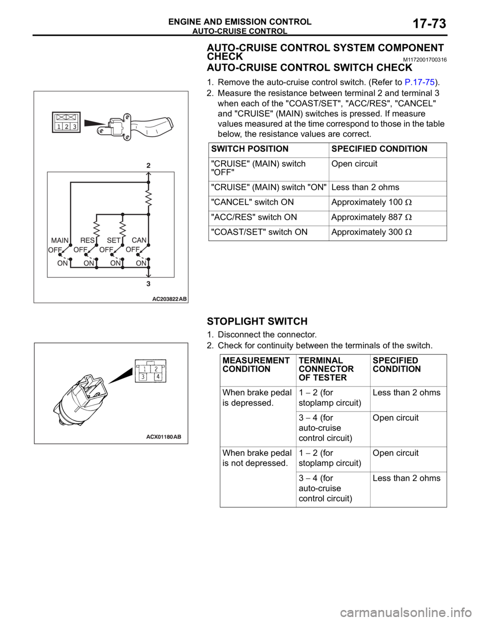
AUTO-CRUISE CONTROL SWITCH CHECK
1. Remove the auto-cruise control switch. (Refer to P.17-75).
2. Measure the resistance between terminal 2 and terminal 3
when each of the "COAST/SET", "ACC/RES", "CANCEL"
and "CRUISE" (MAIN) switches is pressed. If measure
values measured at the time correspond to those in the table
below, the resistance values are correct.
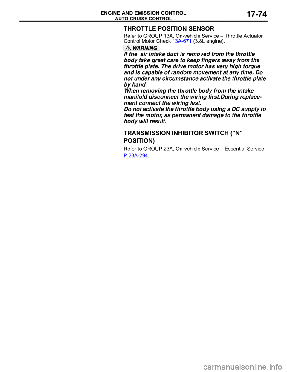
STOPLIGHT SWITCH
1. Disconnect the connector.
2. Check for continuity between the terminals of the switch.SWITCH POSITION SPECIFIED CONDITION
"CRUISE" (MAIN) switch
"OFF"Open circuit
"CRUISE" (MAIN) switch "ON" Less than 2 ohms
"CANCEL" switch ON Approximately 100
"ACC/RES" switch ON Approximately 887
"COAST/SET" switch ON Approximately 300
MEASUREMENT
CONDITIONTERMINAL
CONNECTOR
OF TESTERSPECIFIED
CONDITION
When brake pedal
is depressed.1
2 (for
stoplamp circuit)Less than 2 ohms
3
4 (for
auto-cruise
control circuit)Open circuit
When brake pedal
is not depressed.1
2 (for
stoplamp circuit)Open circuit
3
4 (for
auto-cruise
control circuit)Less than 2 ohms
AUTO-CRUISE CONTROL
ENGINE AND EMISSION CONTROL17-74
THROTTLE POSITION SENSOR
Refer to GROUP 13A, On-vehicle Service Throttle Actuator
Control Motor Check 13A-671 (3.8L engine).
If the air intake duct is removed from the throttle
body take great care to keep fingers away from the
throttle plate. The drive motor has very high torque
and is capable of random movement at any time. Do
not under any circumstance activate the throttle plate
by hand.
When removing the throttle body from the intake
manifold disconnect the wiring first.During replace-
ment connect the wiring last.
Do not activate the throttle body using a DC supply to
test the motor, as permanent damage to the throttle
body will result.
TRANSMISSION INHIBITOR SWITCH ("N"
POSITION)
Refer to GROUP 23A, On-vehicle Service Essential Service
P.23A-294.
AUTO-CRUISE CONTROL
ENGINE AND EMISSION CONTROL17-75
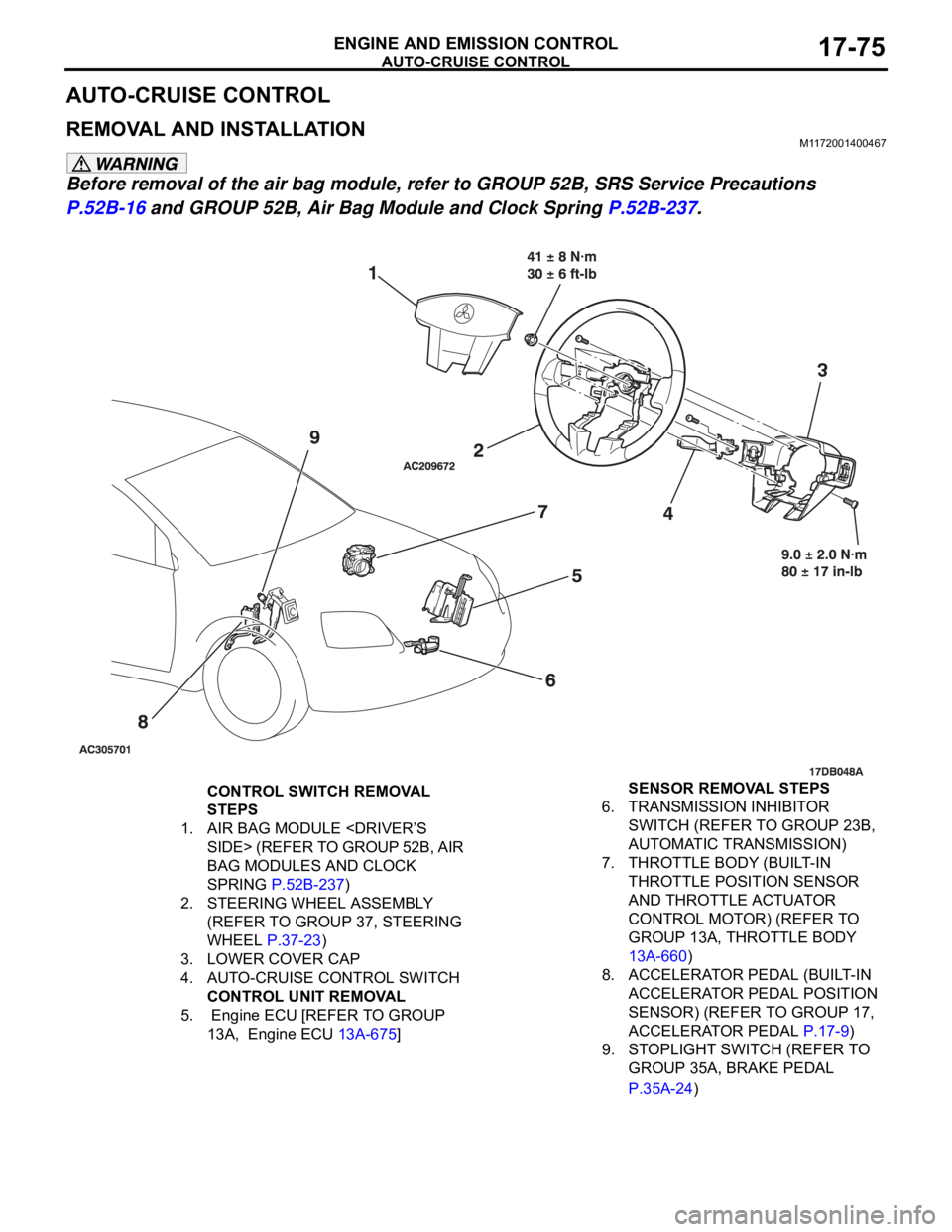
AUTO-CRUISE CONTROL
REMOVAL AND INSTALLATIONM1172001400467
Before removal of the air bag module, refer to GROUP 52B, SRS Service Precautions
P.52B-16 and GROUP 52B, Air Bag Module and Clock Spring P.52B-237.
CONTROL SWITCH REMOVAL
STEPS
1. AIR BAG MODULE
SIDE> (REFER TO GROUP 52B, AIR
BAG MODULES AND CLOCK
SPRING P.52B-237)
2. STEERING WHEEL ASSEMBLY
(REFER TO GROUP 37, STEERING
WHEEL P.37-23)
3. LOWER COVER CAP
4. AUTO-CRUISE CONTROL SWITCH
CONTROL UNIT REMOVAL
5. Engine ECU [REFER TO GROUP
13A, Engine ECU 13A-675] SENSOR REMOVAL STEPS
6. TRANSMISSION INHIBITOR
SWITCH (REFER TO GROUP 23B,
AUTOMATIC TRANSMISSION)
7. THROTTLE BODY (BUILT-IN
THROTTLE POSITION SENSOR
AND THROTTLE ACTUATOR
CONTROL MOTOR) (REFER TO
GROUP 13A, THROTTLE BODY
13A-660)
8. ACCELERATOR PEDAL (BUILT-IN
ACCELERATOR PEDAL POSITION
SENSOR) (REFER TO GROUP 17,
ACCELERATOR PEDAL P.17-9)
9. STOPLIGHT SWITCH (REFER TO
GROUP 35A, BRAKE PEDAL
P.35A-24)
SPECIFICATIONS
ENGINE AND EMISSION CONTROL17-85
SPECIFICATIONS
FASTENER TIGHTENING SPECIFICATIONSM1173006400324
SERVICE SPECIFICATIONSM1173000300545
ITEM SPECIFICATION
Auto-cruise control system
Lower cover cap bolt 9.0
2.0 Nm (80 17 in-lb)
Steering wheel assembly nut 41
8 Nm (30 6 ft-lb)
Engine control system
Accelerator pedal assembly nut 13
2 Nm ( 111 22 in-lb)
ITEMSSTANDARD VALUE
Engine control system
Curb idle speed r/min 3.8L Engine 680
100
Emission control system
Purge flow cm
3/s (SCFH) [at 80 95C (176 205F) with sudden revving]20 (2.5)
Evaporative emission purge solenoid coil resistance [at 20
C)] 16


