MITSUBISHI ASX 2009 1.G Owners Manual
Manufacturer: MITSUBISHI, Model Year: 2009, Model line: ASX, Model: MITSUBISHI ASX 2009 1.GPages: 368, PDF Size: 8.13 MB
Page 271 of 368
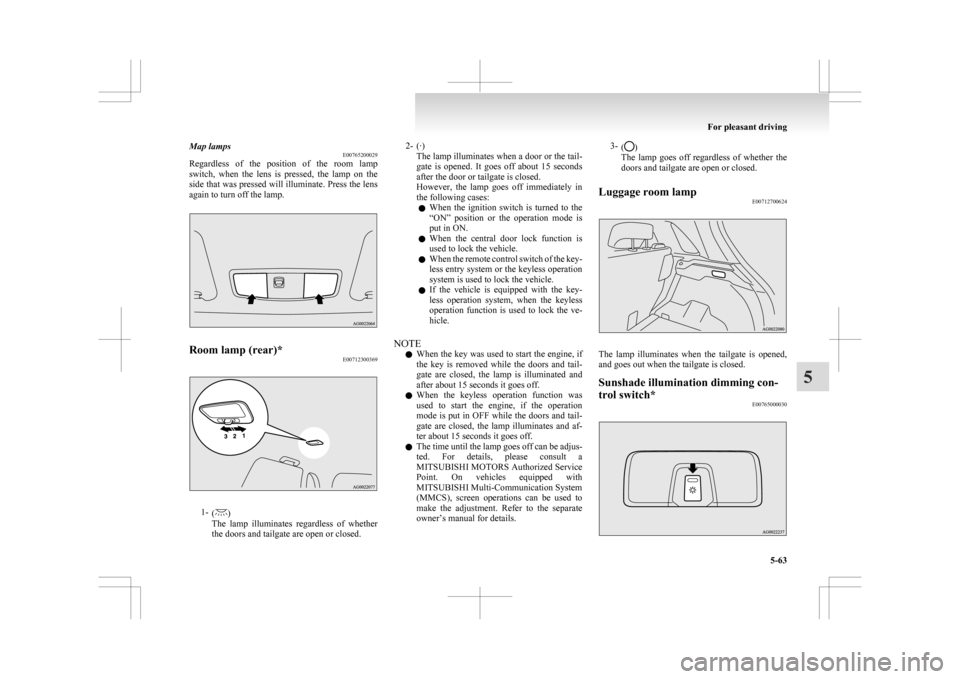
Map lamps
E00765200029
Regardless
of the position of the room lamp
switch, when the lens is pressed, the lamp on the
side that was pressed will illuminate. Press the lens
again to turn off the lamp. Room lamp (rear)*
E007123003691-
( )
The
lamp illuminates regardless of whether
the doors and tailgate are open or closed. 2- (·)
The
lamp illuminates when a door or the tail-
gate is opened. It goes off about 15 seconds
after the door or tailgate is closed.
However, the lamp goes off immediately in
the following cases:
l When the ignition switch is turned to the
“ON” position or the operation mode is
put in ON.
l When the central door lock function is
used to lock the vehicle.
l When the remote control switch of the key-
less entry system or the keyless operation
system is used to lock the vehicle.
l If the vehicle is equipped with the key-
less operation system, when the keyless
operation function is used to lock the ve-
hicle.
NOTE l When the key was used to start the engine, if
the key is removed while the doors and tail-
gate are closed, the lamp is illuminated and
after about 15 seconds it goes off.
l When the keyless operation function was
used to start the engine, if the operation
mode is put in OFF while the doors and tail-
gate are closed, the lamp illuminates and af-
ter about 15 seconds it goes off.
l The time until the lamp goes off can be adjus-
ted. For details, please consult a
MITSUBISHI MOTORS Authorized Service
Point. On vehicles equipped with
MITSUBISHI Multi-Communication System
(MMCS), screen operations can be used to
make the adjustment. Refer to the separate
owner’s manual for details. 3-
( )
The lamp goes off regardless of whether the
doors and tailgate are open or closed.
Luggage room lamp E00712700624 The lamp illuminates when the tailgate is opened,
and goes out when the tailgate is closed.
Sunshade illumination dimming con-
trol switch*
E00765000030 For pleasant driving
5-63 5
Page 272 of 368
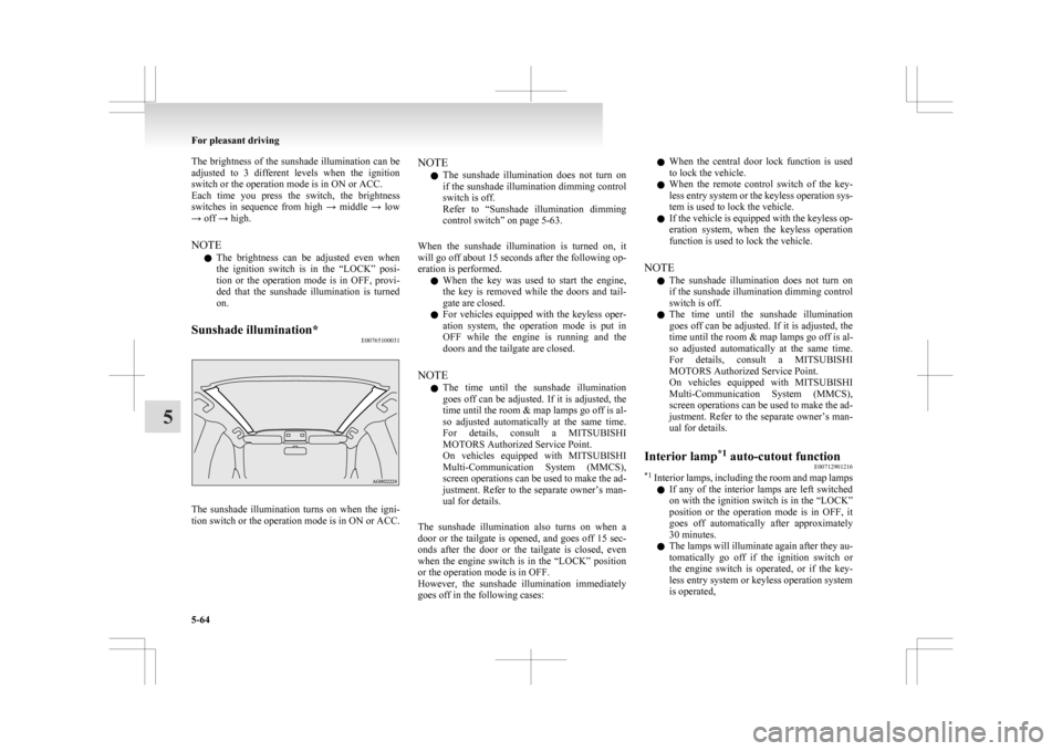
The brightness of the sunshade illumination can be
adjusted
to 3 different levels when the ignition
switch or the operation mode is in ON or ACC.
Each time you press the switch, the brightness
switches in sequence from high → middle → low
→ off → high.
NOTE
l The brightness can be adjusted even when
the ignition switch is in the “LOCK” posi-
tion or the operation mode is in OFF, provi-
ded that the sunshade illumination is turned
on.
Sunshade illumination* E00765100031The sunshade illumination turns on when the igni-
tion
switch or the operation mode is in ON or ACC. NOTE
l The
sunshade illumination does not turn on
if the sunshade illumination dimming control
switch is off.
Refer to “Sunshade illumination dimming
control switch” on page 5-63.
When the sunshade illumination is turned on, it
will go off about 15 seconds after the following op-
eration is performed. l When the key was used to start the engine,
the key is removed while the doors and tail-
gate are closed.
l For vehicles equipped with the keyless oper-
ation system, the operation mode is put in
OFF while the engine is running and the
doors and the tailgate are closed.
NOTE l The time until the sunshade illumination
goes off can be adjusted. If it is adjusted, the
time until the room & map lamps go off is al-
so adjusted automatically at the same time.
For details, consult a MITSUBISHI
MOTORS Authorized Service Point.
On vehicles equipped with MITSUBISHI
Multi-Communication System (MMCS),
screen operations can be used to make the ad-
justment. Refer to the separate owner’s man-
ual for details.
The sunshade illumination also turns on when a
door or the tailgate is opened, and goes off 15 sec-
onds after the door or the tailgate is closed, even
when the engine switch is in the “LOCK” position
or the operation mode is in OFF.
However, the sunshade illumination immediately
goes off in the following cases: l
When the central door lock function is used
to lock the vehicle.
l When the remote control switch of the key-
less entry system or the keyless operation sys-
tem is used to lock the vehicle.
l If the vehicle is equipped with the keyless op-
eration system, when the keyless operation
function is used to lock the vehicle.
NOTE l The sunshade illumination does not turn on
if the sunshade illumination dimming control
switch is off.
l The time until the sunshade illumination
goes off can be adjusted. If it is adjusted, the
time until the room & map lamps go off is al-
so adjusted automatically at the same time.
For details, consult a MITSUBISHI
MOTORS Authorized Service Point.
On vehicles equipped with MITSUBISHI
Multi-Communication System (MMCS),
screen operations can be used to make the ad-
justment. Refer to the separate owner’s man-
ual for details.
Interior lamp *1
auto-cutout function
E00712901216
*1
Interior lamps, including the room and map lamps
l If any of the interior lamps are left switched
on with the ignition switch is in the “LOCK”
position or the operation mode is in OFF, it
goes off automatically after approximately
30 minutes.
l The lamps will illuminate again after they au-
tomatically go off if the ignition switch or
the engine switch is operated, or if the key-
less entry system or keyless operation system
is operated, For pleasant driving
5-64
5
Page 273 of 368
NOTE
l The
interior lamp auto cut-out function can
be deactivated. The time until the lamps auto-
matically go off can be adjusted. For details
and support, consult your nearest
MITSUBISHI MOTORS Authorized Service
Point.
On vehicles equipped with MITSUBISHI
Multi-Communication System (MMCS),
screen operations can be used to make the ad-
justment. Refer to the separate owner’s man-
ual for details. Storage spaces
E00713101664 CAUTION
l
Never
leave lighters, cans of carbonated
drink, and spectacles in the cabin when
parking the vehicle in hot sunshine. The
cabin will become extremely hot, so light-
ers and other flammable items may catch
fire and unopened drink cans (including
soft drink or beer cans) may rupture. Al-
so, spectacles with plastic lenses or mate-
rials could deform or crack.
l Keep the lids of storage spaces closed
while driving the vehicle. A lid or the con-
tents of a storage space could otherwise
cause injuries.
NOTE l When
leaving your vehicle, do not leave val-
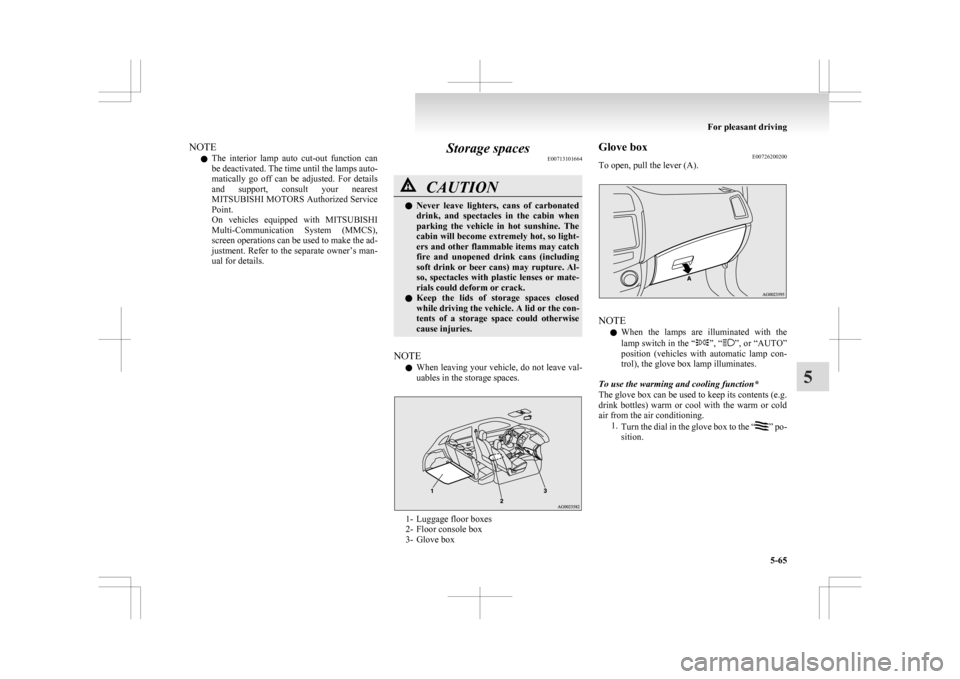
uables in the storage spaces. 1- Luggage floor boxes
2-
Floor console box
3- Glove box Glove box
E00726200200
To open, pull the lever (A). NOTE
l When
the lamps are illuminated with the
lamp switch in the “ ”, “ ”,
or “AUTO”
position (vehicles with automatic lamp con-
trol), the glove box lamp illuminates.
To use the warming and cooling function*
The glove box can be used to keep its contents (e.g.
drink bottles) warm or cool with the warm or cold
air from the air conditioning. 1.Turn the dial in the glove box to the “ ”
po-
sition. For pleasant driving
5-65 5
Page 274 of 368
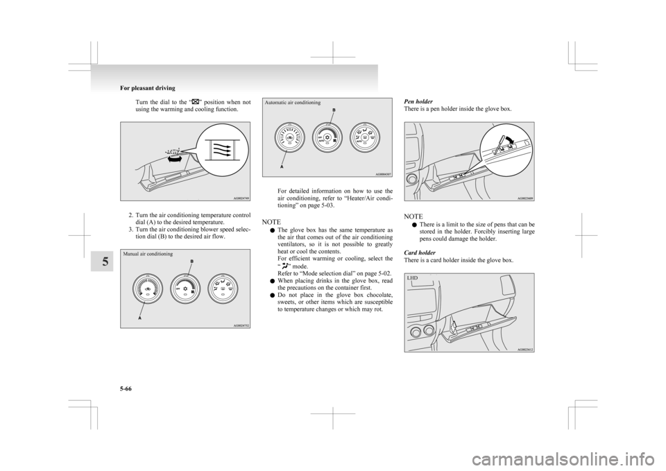
Turn the dial to the “ ” position when not
using the warming and cooling function. 2. Turn
the air conditioning temperature control
dial (A) to the desired temperature.
3. Turn the air conditioning blower speed selec- tion dial (B) to the desired air flow.
Manual air conditioning
Automatic air conditioning For detailed information on how to use the
air
conditioning, refer to “Heater/Air condi-
tioning” on page 5-03.
NOTE l The glove box has the same temperature as
the air that comes out of the air conditioning
ventilators, so it is not possible to greatly
heat or cool the contents.
For efficient warming or cooling, select the
“ ” mode.
Refer to “Mode selection dial” on page
5-02.
l When placing drinks in the glove box, read
the precautions on the container first.
l Do not place in the glove box chocolate,
sweets, or other items which are susceptible
to temperature changes or which may rot. Pen holder
There is a pen holder inside the glove box.
NOTE
l There
is a limit to the size of pens that can be
stored in the holder. Forcibly inserting large
pens could damage the holder.
Card holder
There is a card holder inside the glove box. For pleasant driving
5-66
5 LHD
Page 275 of 368
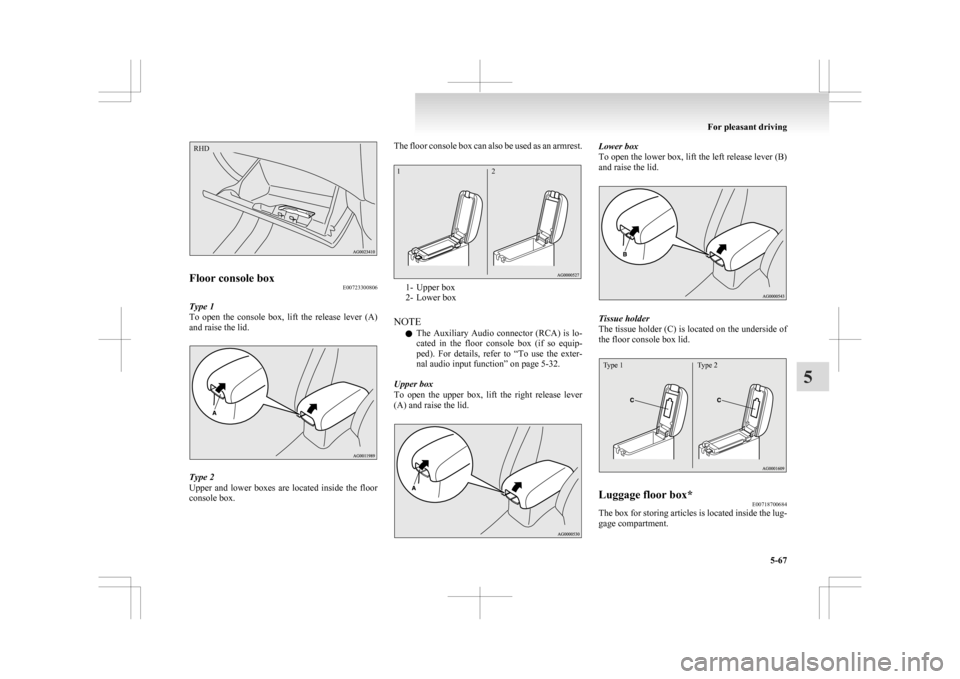
Floor console box
E00723300806
Type 1
To open the console box, lift the release lever (A)
and raise the lid. Type 2
Upper
and lower boxes are located inside the floor
console box. The floor console box can also be used as an armrest.
1- Upper box
2-
Lower box
NOTE l The Auxiliary Audio connector (RCA) is lo-
cated in the floor console box (if so equip-
ped). For details, refer to “To use the exter-
nal audio input function” on page 5-32.
Upper box
To open the upper box, lift the right release lever
(A) and raise the lid. Lower box
To
open the lower box, lift the left release lever (B)
and raise the lid. Tissue holder
The
tissue holder (C) is located on the underside of
the floor console box lid.
Type 1 Type 2 Luggage floor box*
E00718700684
The box for storing articles is located inside the lug-
gage compartment. For pleasant driving
5-67 5RHD 1
2
Page 276 of 368
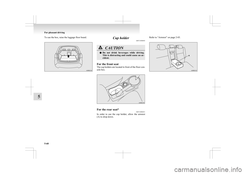
To use the box, raise the luggage floor board.
Cup holder
E00714500945 CAUTION
l
Do not drink beverages while driving.
This is distracting and could cause an ac-
cident.
For the front seat
The
cup holders are located in front of the floor con-
sole box. For the rear seat*
E00716900451
In order to use the cup holder, allow the armrest
(A) to drop down. Refer to “Armrest” on page 2-05.For pleasant driving
5-68
5
Page 277 of 368
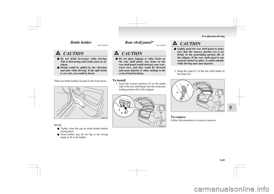
Bottle holder
E00718200328CAUTION
l
Do not drink beverages while driving.
This is distracting and could cause an ac-
cident.
l Drinks could be spilled by the vibration
and jolts while driving. If the spilt drink
is very hot, you could be burnt.
There are bottle holders located on the front doors. NOTE
l Tightly
close the cap on drink bottles before
storing them.
l Some bottles may be too big or the wrong
shape to fit in the holder. Rear shelf panel*
E00715400114 CAUTION
l
Do
not place luggage or other items on
the rear shelf panel. Any items on the
rear shelf panel would obstruct your rear-
ward view, and they could fly forward
and cause injuries or other mishap in the
event of hard braking.
To install 1. Insert
the concave portion (A) on the under-
side of the rear shelf panel into the inside pro-
truding portion (B) of the tailgate. CAUTION
l
Lightly
push the rear shelf panel to make
sure that the concave portion (A) is set
firmly in the protruding portion (B) of
the tailgate. If the rear shelf panel is not
securely locked in place, it could unhook
while driving and cause injuries.
2. Hang
the strap (C) of the rear shelf panel on the hook (D). To remove
Follow this procedure in reverse to remove. For pleasant driving
5-69 5
Page 278 of 368
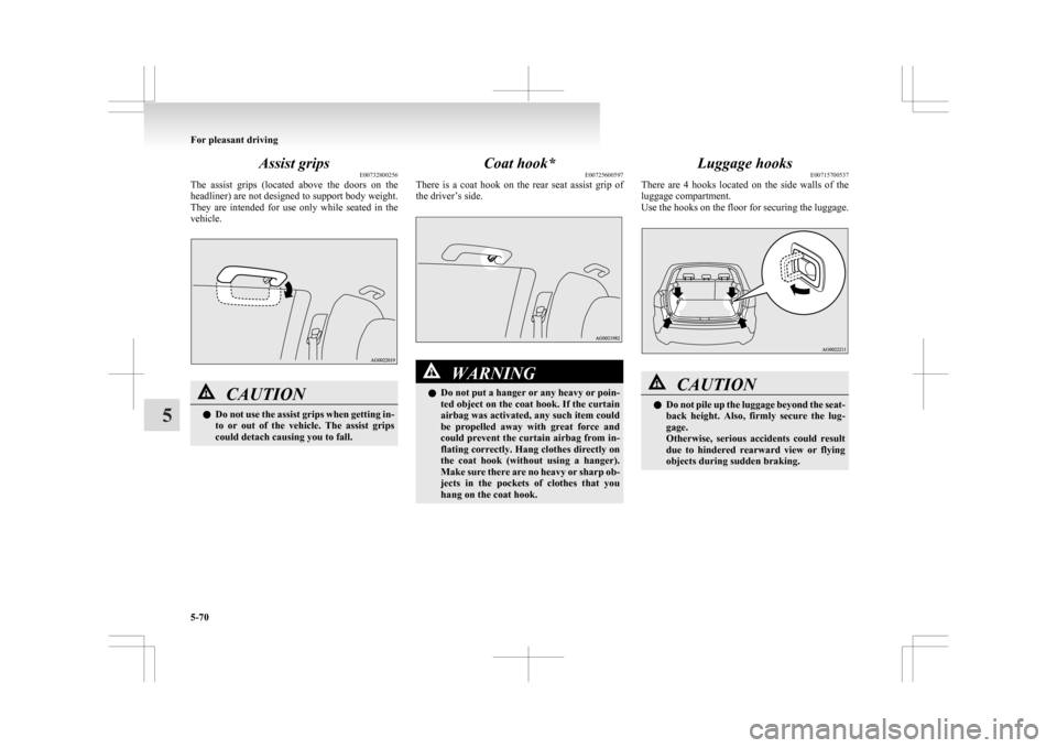
Assist grips
E00732800256
The
assist grips (located above the doors on the
headliner) are not designed to support body weight.
They are intended for use only while seated in the
vehicle. CAUTION
l
Do
not use the assist grips when getting in-
to or out of the vehicle. The assist grips
could detach causing you to fall. Coat hook*
E00725600597
There
is a coat hook on the rear seat assist grip of
the driver’s side. WARNING
l Do
not put a hanger or any heavy or poin-
ted object on the coat hook. If the curtain
airbag was activated, any such item could
be propelled away with great force and
could prevent the curtain airbag from in-
flating correctly. Hang clothes directly on
the coat hook (without using a hanger).
Make sure there are no heavy or sharp ob-
jects in the pockets of clothes that you
hang on the coat hook. Luggage hooks
E00715700537
There
are 4 hooks located on the side walls of the
luggage compartment.
Use the hooks on the floor for securing the luggage. CAUTION
l
Do
not pile up the luggage beyond the seat-
back height. Also, firmly secure the lug-
gage.
Otherwise, serious accidents could result
due to hindered rearward view or flying
objects during sudden braking. For pleasant driving
5-70
5
Page 279 of 368
If the vehicle breaks down
............................................................ 6-02
Emergency starting ....................................................................... 6-02
Engine overheating ....................................................................... 6-04
Tools, jack and tyre repair kit ....................................................... 6-06
How to change a tyre .................................................................... 6-12
Towing.......................................................................................... 6-19
Operation under adverse driving conditions .................................6-22For emergencies
6
Page 280 of 368
If the vehicle breaks down
E00800101108
If
the vehicle breaks down on the road, move it to
the shoulder and turn on the hazard warning flash-
ers and set up a warning triangle, flashing lamp, etc.
Refer to “Hazard warning flasher switch” on page
3-50.
If the engine stops/fails
Vehicle operation and control are affected if the en-
gine stops.
Before moving the vehicle to a safe area, be aware
of the following:
l The brake booster becomes inoperative and
the pedal effort will increase. Press down the
brake pedal harder than usual.
l Since the power steering system is no longer
operative, the steering wheel feels heavy
when turning it. Emergency starting
E00800502503
If
the engine cannot be started because the battery
is weak or dead, the battery from another vehicle
can be used with jumper cables to start the engine. WARNING
l To
start the engine using jumper cables
connected to another vehicle, perform the
correct procedures according to the in-
struction below. Incorrect procedures
could result in a fire or explosion or dam-
age to the vehicles. CAUTION
l
Do
not attempt to start the engine by pull-
ing or pushing the vehicle.
It could damage your vehicle.
l Always wear protective eye goggles when
working near the battery.
l Keep the battery out of the reach of chil-
dren.
1. Get
the vehicles close enough so the jumper cables can reach, but be sure the vehicles
aren’t touching each other. CAUTION
l
Check
the other vehicle. It must have a 12-
volt battery.
If the other system isn’t 12-volt, shorting
can damage both vehicles. 2. Turn
off all lamps, heater and other electrical
loads.
3. Set the parking brake firmly on each vehicle. Put an A/T, CVT in “P” (PARK) or a M/T in
“N” (Neutral).
4. Turn the ignition switch to the “LOCK” posi- tion or put the operation mode in OFF. WARNING
l Perform
step 4 on both vehicles before-
hand.
Make sure that the cables or your clothes
cannot be caught by the fan or drive belt.
Personal injury could result.
5. Make
sure battery electrolyte is at the proper level.
Refer to “Battery” on page 8-08. WARNING
l If
electrolyte fluid is not visible, or ap-
pears to be frozen, Do Not Attempt Jump
Starting!
A battery might rupture or explode if the
temperature is below the freezing point
or if it is not filled to the proper level.
6. Connect
one end of one jumper cable to the positive (+) terminal of the discharged bat-
tery (A), and the other end to the positive (+)
terminal of the booster battery (B).
For emergencies
6-02
6