MITSUBISHI ASX 2009 1.G Owners Manual
Manufacturer: MITSUBISHI, Model Year: 2009, Model line: ASX, Model: MITSUBISHI ASX 2009 1.GPages: 368, PDF Size: 8.13 MB
Page 311 of 368
8. After adding oil, close the cap securely.
9.
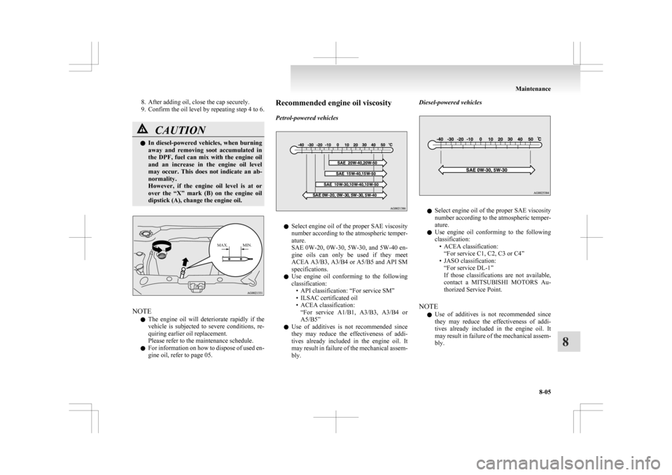
Confirm the oil level by repeating step 4 to 6. CAUTION
l
In
diesel-powered vehicles, when burning
away and removing soot accumulated in
the DPF, fuel can mix with the engine oil
and an increase in the engine oil level
may occur. This does not indicate an ab-
normality.
However, if the engine oil level is at or
over the “X” mark (B) on the engine oil
dipstick (A), change the engine oil.
MAX. MIN. NOTE
l The
engine oil will deteriorate rapidly if the
vehicle is subjected to severe conditions, re-
quiring earlier oil replacement.
Please refer to the maintenance schedule.
l For information on how to dispose of used en-
gine oil, refer to page 05. Recommended engine oil viscosity
Petrol-powered vehicles
l
Select
engine oil of the proper SAE viscosity
number according to the atmospheric temper-
ature.
SAE 0W-20, 0W-30, 5W-30, and 5W-40 en-
gine oils can only be used if they meet
ACEA A3/B3, A3/B4 or A5/B5 and API SM
specifications.
l Use engine oil conforming to the following
classification:
• API classification: “For service SM”
• ILSAC certificated oil
• ACEA classification:“For service A1/B1, A3/B3, A3/B4 or
A5/B5”
l Use of additives is not recommended since
they may reduce the effectiveness of addi-
tives already included in the engine oil. It
may result in failure of the mechanical assem-
bly. Diesel-powered vehicles
l
Select
engine oil of the proper SAE viscosity
number according to the atmospheric temper-
ature.
l Use engine oil conforming to the following
classification:
• ACEA classification:“For service C1, C2, C3 or C4”
• JASO classification: “For service DL-1”
If those classifications are not available,
contact a MITSUBISHI MOTORS Au-
thorized Service Point.
NOTE l Use of additives is not recommended since
they may reduce the effectiveness of addi-
tives already included in the engine oil. It
may result in failure of the mechanical assem-
bly. Maintenance
8-05 8
Page 312 of 368
Engine coolant
E01000501547
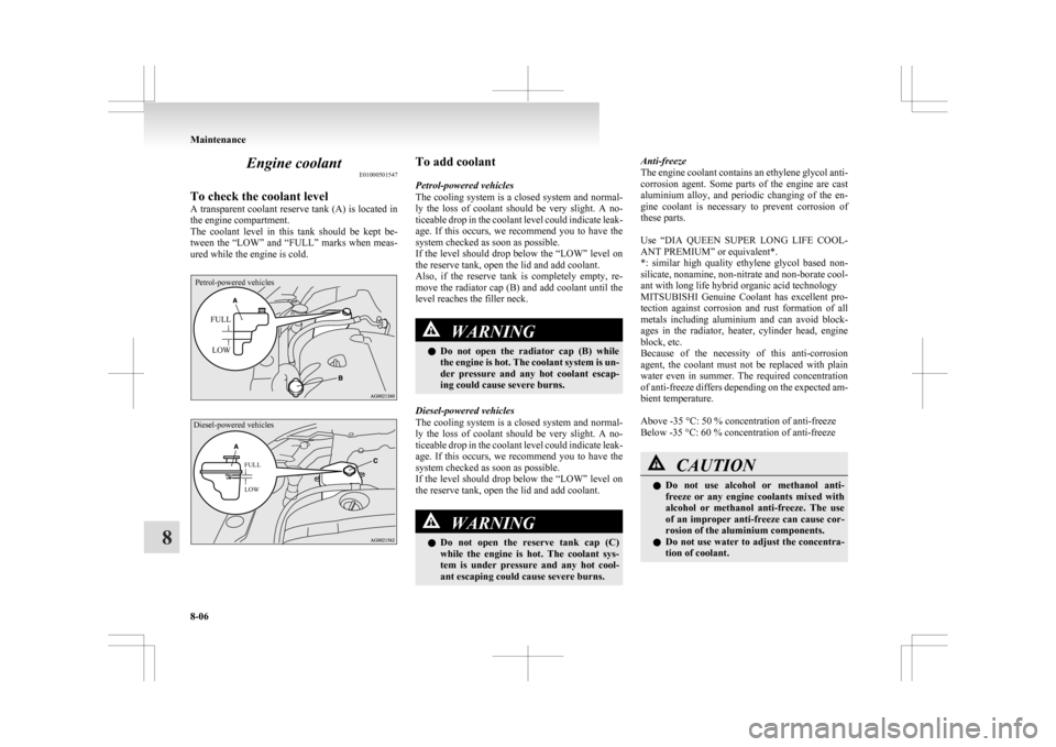
To check the coolant level
A
transparent coolant reserve tank (A) is located in
the engine compartment.
The coolant level in this tank should be kept be-
tween the “LOW” and “FULL” marks when meas-
ured while the engine is cold.
Petrol-powered vehicles
FULLLOW
Diesel-powered vehicles
FULL
LOW To add coolant
Petrol-powered vehicles
The
cooling system is a closed system and normal-
ly the loss of coolant should be very slight. A no-
ticeable drop in the coolant level could indicate leak-
age. If this occurs, we recommend you to have the
system checked as soon as possible.
If the level should drop below the “LOW” level on
the reserve tank, open the lid and add coolant.
Also, if the reserve tank is completely empty, re-
move the radiator cap (B) and add coolant until the
level reaches the filler neck. WARNING
l Do
not open the radiator cap (B) while
the engine is hot. The coolant system is un-
der pressure and any hot coolant escap-
ing could cause severe burns.
Diesel-powered vehicles
The
cooling system is a closed system and normal-
ly the loss of coolant should be very slight. A no-
ticeable drop in the coolant level could indicate leak-
age. If this occurs, we recommend you to have the
system checked as soon as possible.
If the level should drop below the “LOW” level on
the reserve tank, open the lid and add coolant. WARNING
l Do
not open the reserve tank cap (C)
while the engine is hot. The coolant sys-
tem is under pressure and any hot cool-
ant escaping could cause severe burns. Anti-freeze
The
engine coolant contains an ethylene glycol anti-
corrosion agent. Some parts of the engine are cast
aluminium alloy, and periodic changing of the en-
gine coolant is necessary to prevent corrosion of
these parts.
Use “DIA QUEEN SUPER LONG LIFE COOL-
ANT PREMIUM” or equivalent*.
*: similar high quality ethylene glycol based non-
silicate, nonamine, non-nitrate and non-borate cool-
ant with long life hybrid organic acid technology
MITSUBISHI Genuine Coolant has excellent pro-
tection against corrosion and rust formation of all
metals including aluminium and can avoid block-
ages in the radiator, heater, cylinder head, engine
block, etc.
Because of the necessity of this anti-corrosion
agent, the coolant must not be replaced with plain
water even in summer. The required concentration
of anti-freeze differs depending on the expected am-
bient temperature.
Above -35 °C: 50 % concentration of anti-freeze
Below -35 °C: 60 % concentration of anti-freeze CAUTION
l
Do
not use alcohol or methanol anti-
freeze or any engine coolants mixed with
alcohol or methanol anti-freeze. The use
of an improper anti-freeze can cause cor-
rosion of the aluminium components.
l Do not use water to adjust the concentra-
tion of coolant. Maintenance
8-06
8
Page 313 of 368
CAUTION
l
Concentrations exceeding 60 % will re-
sult in a reduction of both the anti-freeze
and cooling performance thus adversely
affecting the engine.
l Do not top up with water only.
Water by itself reduces the rust-protec-
tive and anti-freeze qualities of the cool-
ant and has a lower boiling point. It can
also cause damage to the cooling system if
it should freeze. Do not use tapwater, as it
can cause corrosion and rust formation.
During cold weather
If
the temperatures in your area drop below freez-
ing, there is the danger that the coolant in the en-
gine or radiator could freeze and cause severe dam-
age to the engine and/or radiator. Add a sufficient
amount of anti-freeze to the coolant to prevent it
from freezing.
The concentration should be checked before the
start of cold weather and anti-freeze added to the
system if necessary. Washer fluid
E01000700832
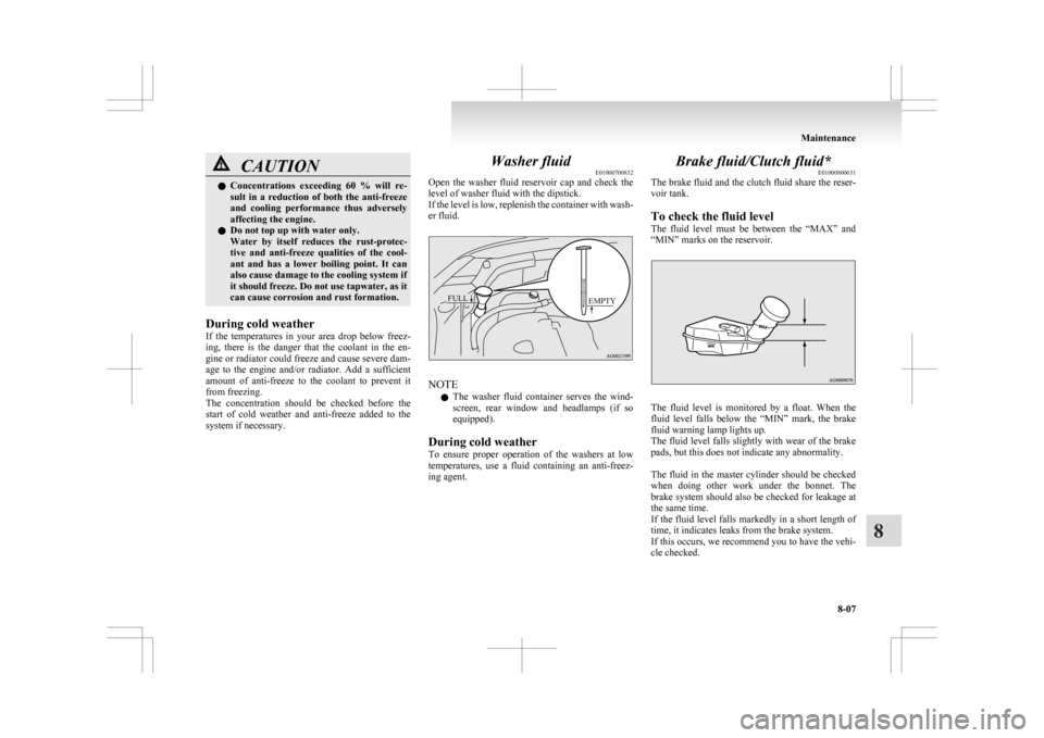
Open
the washer fluid reservoir cap and check the
level of washer fluid with the dipstick.
If the level is low, replenish the container with wash-
er fluid.
EMPTY
FULL NOTE
l The
washer fluid container serves the wind-
screen, rear window and headlamps (if so
equipped).
During cold weather
To ensure proper operation of the washers at low
temperatures, use a fluid containing an anti-freez-
ing agent. Brake fluid/Clutch fluid*
E01000800631
The
brake fluid and the clutch fluid share the reser-
voir tank.
To check the fluid level
The fluid level must be between the “MAX” and
“MIN” marks on the reservoir. The fluid level is monitored by a float. When the
fluid
level falls below the “MIN” mark, the brake
fluid warning lamp lights up.
The fluid level falls slightly with wear of the brake
pads, but this does not indicate any abnormality.
The fluid in the master cylinder should be checked
when doing other work under the bonnet. The
brake system should also be checked for leakage at
the same time.
If the fluid level falls markedly in a short length of
time, it indicates leaks from the brake system.
If this occurs, we recommend you to have the vehi-
cle checked. Maintenance
8-07 8
Page 314 of 368
Fluid type
Use
brake fluid conforming to DOT3 or DOT4
from a sealed container. The brake fluid is hygro-
scopic. Too much moisture in the brake fluid will
adversely affect the brake system, reducing the per-
formance. CAUTION
l
Take
care in handling brake fluid as it is
harmful to the eyes, may irritate your
skin and also damage painted surfaces.
l Use only the specified brake fluid.
Do not mix or add different brands of
brake fluid to prevent chemical reactions.
Do not let any petroleum-based fluid
touch, mix with, or get into the brake fluid.
This will damage the seals.
l Keep the reservoir tank cap closed to pre-
vent the brake fluid from deteriorating ex-
cept maintenance.
l Clean the filler cap before removing and
close the cap securely after maintenance. Battery
E01001202131
The
condition of the battery is very important for
quick starting and to keep the vehicle’s electrical
system working properly. Regular inspection and
care are especially important in cold weather.
NOTE
l After replacing the battery, the electronic con-
trol system data for the automatic transmis-
sion, etc., will be erased. As a result, shift
shocks may occur.
Shift shocks will become smoother after sev-
eral changes in speed.
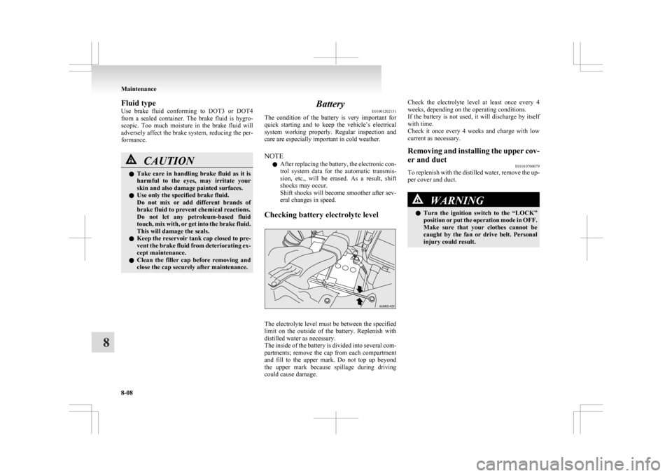
Checking battery electrolyte level The electrolyte level must be between the specified
limit
on the outside of the battery. Replenish with
distilled water as necessary.
The inside of the battery is divided into several com-
partments; remove the cap from each compartment
and fill to the upper mark. Do not top up beyond
the upper mark because spillage during driving
could cause damage. Check the electrolyte level at least once every 4
weeks, depending on the operating conditions.
If
the battery is not used, it will discharge by itself
with time.
Check it once every 4 weeks and charge with low
current as necessary.
Removing and installing the upper cov-
er and duct E01010700079
To replenish with the distilled water, remove the up-
per cover and duct. WARNING
l Turn
the ignition switch to the “LOCK”
position or put the operation mode in OFF.
Make sure that your clothes cannot be
caught by the fan or drive belt. Personal
injury could result. Maintenance
8-08
8
Page 315 of 368
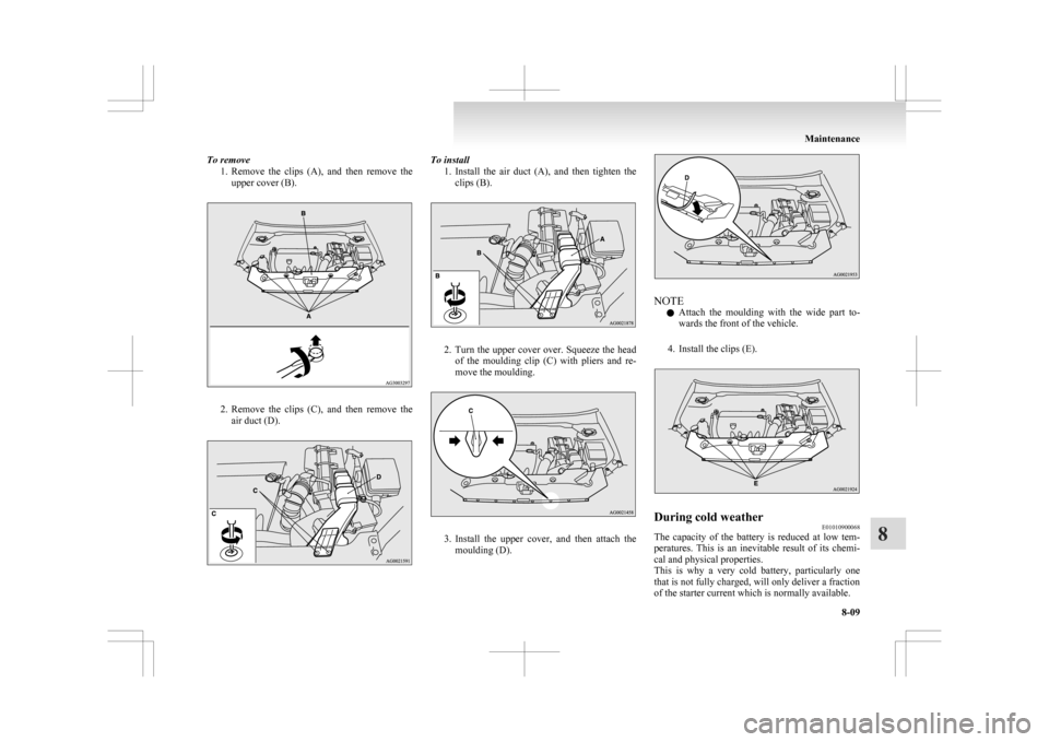
To remove
1. Remove the clips (A), and then remove the
upper cover (B). 2. Remove
the clips (C), and then remove the
air duct (D). To install
1. Install
the air duct (A), and then tighten the
clips (B). 2. Turn
the upper cover over. Squeeze the head
of the moulding clip (C) with pliers and re-
move the moulding. 3. Install
the upper cover, and then attach the
moulding (D). NOTE
l Attach
the moulding with the wide part to-
wards the front of the vehicle.
4. Install the clips (E). During cold weather
E01010900068
The capacity of the battery is reduced at low tem-
peratures.
This is an inevitable result of its chemi-
cal and physical properties.
This is why a very cold battery, particularly one
that is not fully charged, will only deliver a fraction
of the starter current which is normally available. Maintenance
8-09 8
Page 316 of 368
We recommend you to have the battery checked be-
fore
the start of cold weather and, if necessary,
have it charged or replaced.
This does not only ensure reliable starting, but a bat-
tery which is kept fully charged also has a longer life.
Disconnection and connection E01011000079
To disconnect the battery cable, stop the engine,
first
disconnect the negative (-) terminal and then
the positive (+) terminal.
When connecting the battery, first connect the posi-
tive (+) terminal and then the negative (-) terminal.
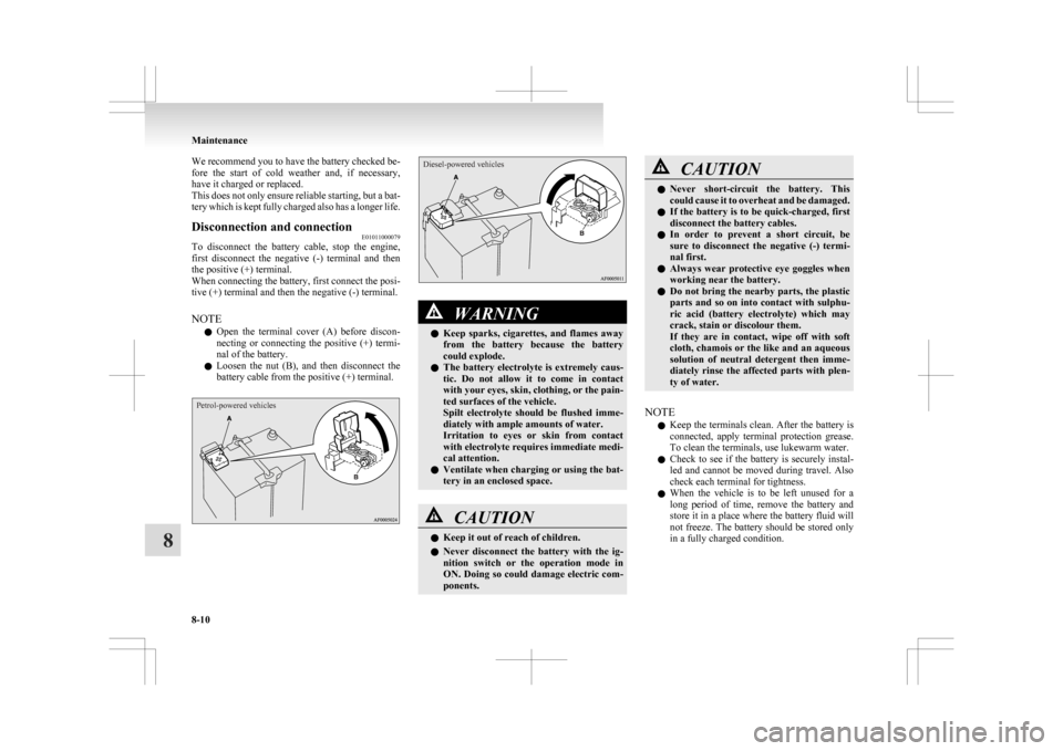
NOTE
l Open the terminal cover (A) before discon-
necting or connecting the positive (+) termi-
nal of the battery.
l Loosen the nut (B), and then disconnect the
battery cable from the positive (+) terminal.
Petrol-powered vehicles
Diesel-powered vehicles WARNING
l Keep
sparks, cigarettes, and flames away
from the battery because the battery
could explode.
l The battery electrolyte is extremely caus-
tic. Do not allow it to come in contact
with your eyes, skin, clothing, or the pain-
ted surfaces of the vehicle.
Spilt electrolyte should be flushed imme-
diately with ample amounts of water.
Irritation to eyes or skin from contact
with electrolyte requires immediate medi-
cal attention.
l Ventilate when charging or using the bat-
tery in an enclosed space. CAUTION
l
Keep it out of reach of children.
l Never
disconnect the battery with the ig-
nition switch or the operation mode in
ON. Doing so could damage electric com-
ponents. CAUTION
l
Never
short-circuit the battery. This
could cause it to overheat and be damaged.
l If the battery is to be quick-charged, first
disconnect the battery cables.
l In order to prevent a short circuit, be
sure to disconnect the negative (-) termi-
nal first.
l Always wear protective eye goggles when
working near the battery.
l Do not bring the nearby parts, the plastic
parts and so on into contact with sulphu-
ric acid (battery electrolyte) which may
crack, stain or discolour them.
If they are in contact, wipe off with soft
cloth, chamois or the like and an aqueous
solution of neutral detergent then imme-
diately rinse the affected parts with plen-
ty of water.
NOTE l Keep
the terminals clean. After the battery is
connected, apply terminal protection grease.
To clean the terminals, use lukewarm water.
l Check to see if the battery is securely instal-
led and cannot be moved during travel. Also
check each terminal for tightness.
l When the vehicle is to be left unused for a
long period of time, remove the battery and
store it in a place where the battery fluid will
not freeze. The battery should be stored only
in a fully charged condition. Maintenance
8-10
8
Page 317 of 368
Tyres
E01001300255 WARNING
l Driving with tyres that are worn, dam-
aged or improperly inflated can lead to a
loss of control or blow out of the tyres
which can result in a collision with seri-
ous or fatal injury. Maintenance
8-11 8
Page 318 of 368
![MITSUBISHI ASX 2009 1.G Owners Manual Tyre inflation pressures
E01001402380Item Tyre size Front Rear At trailer towing
Front Rear
Normal tyre 215/65R16 98H
2.4 bar (35 psi) [240 kPa] 2.4 bar (35 psi) [240 kPa]
215/60R17 96H 2.2 bar (32 ps MITSUBISHI ASX 2009 1.G Owners Manual Tyre inflation pressures
E01001402380Item Tyre size Front Rear At trailer towing
Front Rear
Normal tyre 215/65R16 98H
2.4 bar (35 psi) [240 kPa] 2.4 bar (35 psi) [240 kPa]
215/60R17 96H 2.2 bar (32 ps](/img/19/7566/w960_7566-317.png)
Tyre inflation pressures
E01001402380Item Tyre size Front Rear At trailer towing
Front Rear
Normal tyre 215/65R16 98H
2.4 bar (35 psi) [240 kPa] 2.4 bar (35 psi) [240 kPa]
215/60R17 96H 2.2 bar (32 psi) [220 kPa] 2.2 bar (32 psi) [220 kPa]
Temporary spare tyre T125/90D16
T155/90D16
4.2 bar (60 psi) [420 kPa]
—
215/65R16 2.4 bar (35 psi) [240 kPa] —Check the tyre inflation pressure of all the tyres while they are cold; if insufficient or excessive, adjust to the specified value.
After the tyre inflation pressure has been adjusted, check the tyres for damage and air leaks. Be sure to put caps on the valves.Maintenance
8-12
8
Page 319 of 368
Wheel condition
E010018008851- Location of the tread wear indicator
2-
Tread wear indicator
Check the tyres for cuts, cracks and other damage.
Replace the tyres if there are deep cuts or cracks.
Also check each tyre for pieces of metal or pebbles.
The use of worn tyres can be very dangerous be-
cause of the greater chance of skidding or hydro-
planing. The tread depth of the tyres must exceed
1.6 mm in order for the tyres to meet the minimum
requirement for use.
Tread wear indicators will appear on the surface of
the tyre as the tyre wears, thereby indicating that
the tyre no longer meets the minimum requirement
for use. When these wear indicators appear, the
tyres must be replaced with new ones.
On 4-wheel drive vehicles, when replacement of
any of the tyres is necessary, replace all of them. CAUTION
l
Always
use tyres of the same size, same
type, and same brand, and which have no
wear differences.
Using tyres of different size, type, brands
or degree of wear, will increase the differ-
ential oil temperature, resulting in possi-
ble damage to the driving system. Fur-
ther, the drive train will be subjected to
excessive loading, possibly leading to oil
leakage, component seizure, or other seri-
ous faults.
Replacing tyres and wheels E01007200243 CAUTION
l
Avoid
using different size tyres from the
one listed and the combined use of differ-
ent types of tyres, as this can affect driv-
ing safety.
Refer to “Tyres and wheels” on page
9-12.
l Even if a wheel has the same rim size and
offset as the specified type of wheel, its
shape may prevent it from being fitted cor-
rectly. We recommend you to consult a
specialist before using wheels that you
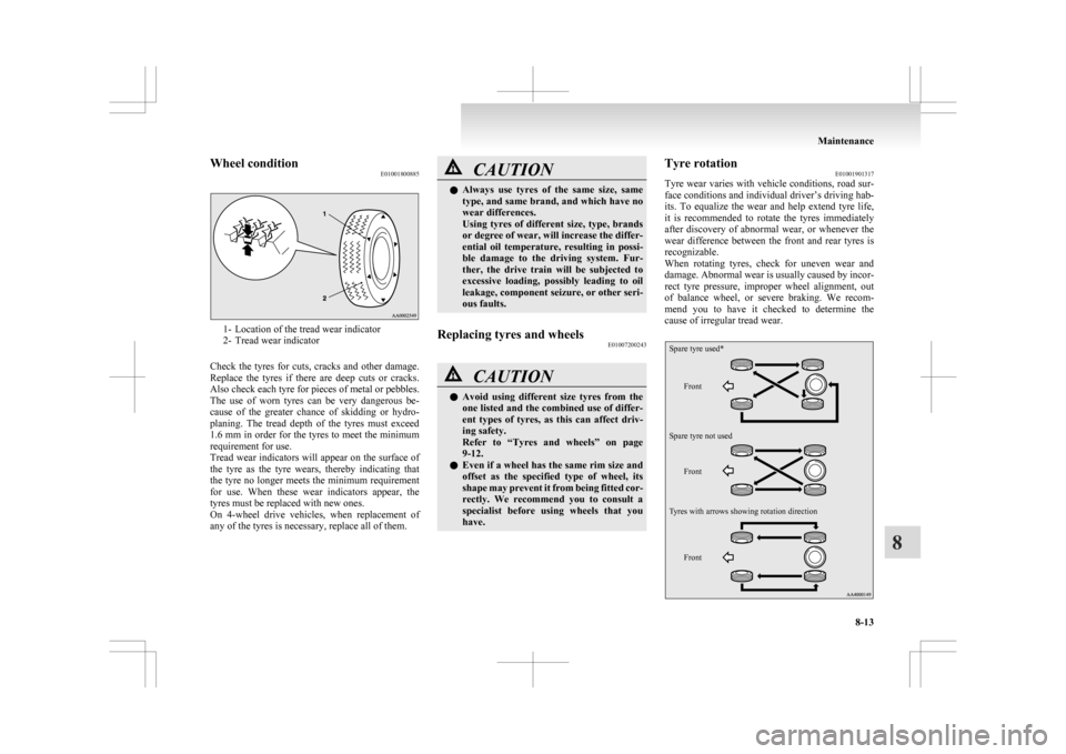
have. Tyre rotation
E01001901317
Tyre
wear varies with vehicle conditions, road sur-
face conditions and individual driver’s driving hab-
its. To equalize the wear and help extend tyre life,
it is recommended to rotate the tyres immediately
after discovery of abnormal wear, or whenever the
wear difference between the front and rear tyres is
recognizable.
When rotating tyres, check for uneven wear and
damage. Abnormal wear is usually caused by incor-
rect tyre pressure, improper wheel alignment, out
of balance wheel, or severe braking. We recom-
mend you to have it checked to determine the
cause of irregular tread wear.
Front Front Front
Spare tyre used*
Spare tyre not used
Tyres with arrows showing rotation direction Maintenance
8-13 8
Page 320 of 368
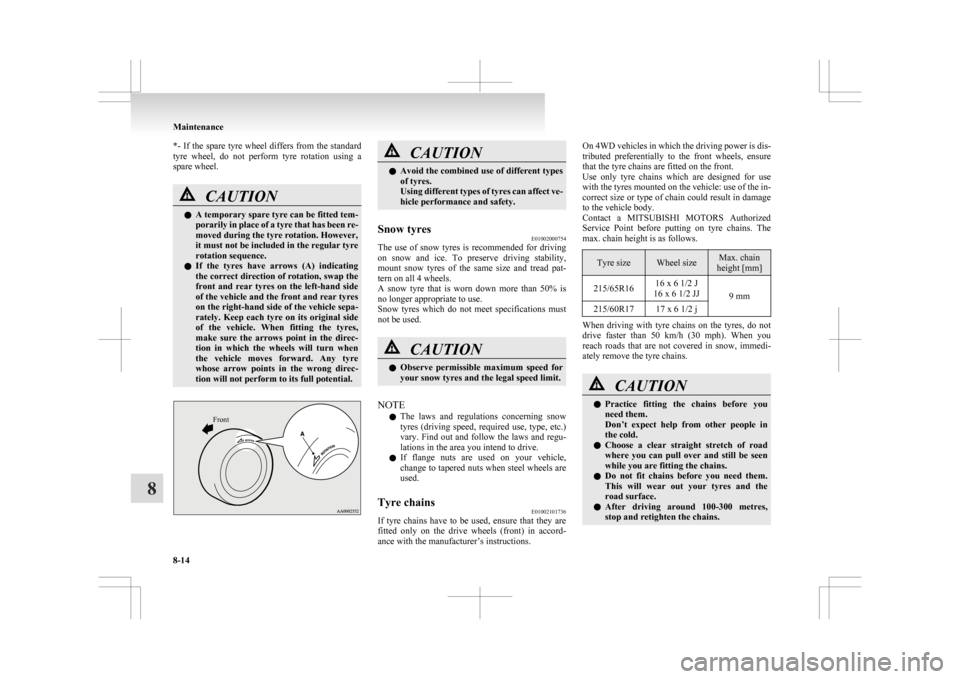
*- If the spare tyre wheel differs from the standard
tyre
wheel, do not perform tyre rotation using a
spare wheel. CAUTION
l
A
temporary spare tyre can be fitted tem-
porarily in place of a tyre that has been re-
moved during the tyre rotation. However,
it must not be included in the regular tyre
rotation sequence.
l If the tyres have arrows (A) indicating
the correct direction of rotation, swap the
front and rear tyres on the left-hand side
of the vehicle and the front and rear tyres
on the right-hand side of the vehicle sepa-
rately. Keep each tyre on its original side
of the vehicle. When fitting the tyres,
make sure the arrows point in the direc-
tion in which the wheels will turn when
the vehicle moves forward. Any tyre
whose arrow points in the wrong direc-
tion will not perform to its full potential.
Front CAUTION
l
Avoid
the combined use of different types
of tyres.
Using different types of tyres can affect ve-
hicle performance and safety.
Snow tyres E01002000754
The use of snow tyres is recommended for driving
on
snow and ice. To preserve driving stability,
mount snow tyres of the same size and tread pat-
tern on all 4 wheels.
A snow tyre that is worn down more than 50% is
no longer appropriate to use.
Snow tyres which do not meet specifications must
not be used. CAUTION
l
Observe
permissible maximum speed for
your snow tyres and the legal speed limit.
NOTE l The
laws and regulations concerning snow
tyres (driving speed, required use, type, etc.)
vary. Find out and follow the laws and regu-
lations in the area you intend to drive.
l If flange nuts are used on your vehicle,
change to tapered nuts when steel wheels are
used.
Tyre chains E01002101736
If tyre chains have to be used, ensure that they are
fitted
only on the drive wheels (front) in accord-
ance with the manufacturer’s instructions. On 4WD vehicles in which the driving power is dis-
tributed
preferentially to the front wheels, ensure
that the tyre chains are fitted on the front.
Use only tyre chains which are designed for use
with the tyres mounted on the vehicle: use of the in-
correct size or type of chain could result in damage
to the vehicle body.
Contact a MITSUBISHI MOTORS Authorized
Service Point before putting on tyre chains. The
max. chain height is as follows. Tyre size Wheel size Max. chain
height [mm]
215/65R16 16 x 6 1/2 J
16 x 6 1/2 JJ 9 mm
215/60R17 17 x 6 1/2 j When driving with tyre chains on the tyres, do not
drive
faster than 50 km/h (30 mph). When you
reach roads that are not covered in snow, immedi-
ately remove the tyre chains. CAUTION
l
Practice
fitting the chains before you
need them.
Don’t expect help from other people in
the cold.
l Choose a clear straight stretch of road
where you can pull over and still be seen
while you are fitting the chains.
l Do not fit chains before you need them.
This will wear out your tyres and the
road surface.
l After driving around 100-300 metres,
stop and retighten the chains. Maintenance
8-14
8