MITSUBISHI COLT 2006 Service Owners Manual
Manufacturer: MITSUBISHI, Model Year: 2006, Model line: COLT, Model: MITSUBISHI COLT 2006Pages: 364, PDF Size: 11.65 MB
Page 91 of 364
OIL PUMP<4A9>
ENGINE LUBRICATION12-4
OIL PUMP<4A9>
M2120002000044
AK305367AB
Timing chain caseOil pump
inner rotor
Oil pump
outer rotor Oil seal
Cover
Machine screw
A
A-A
A
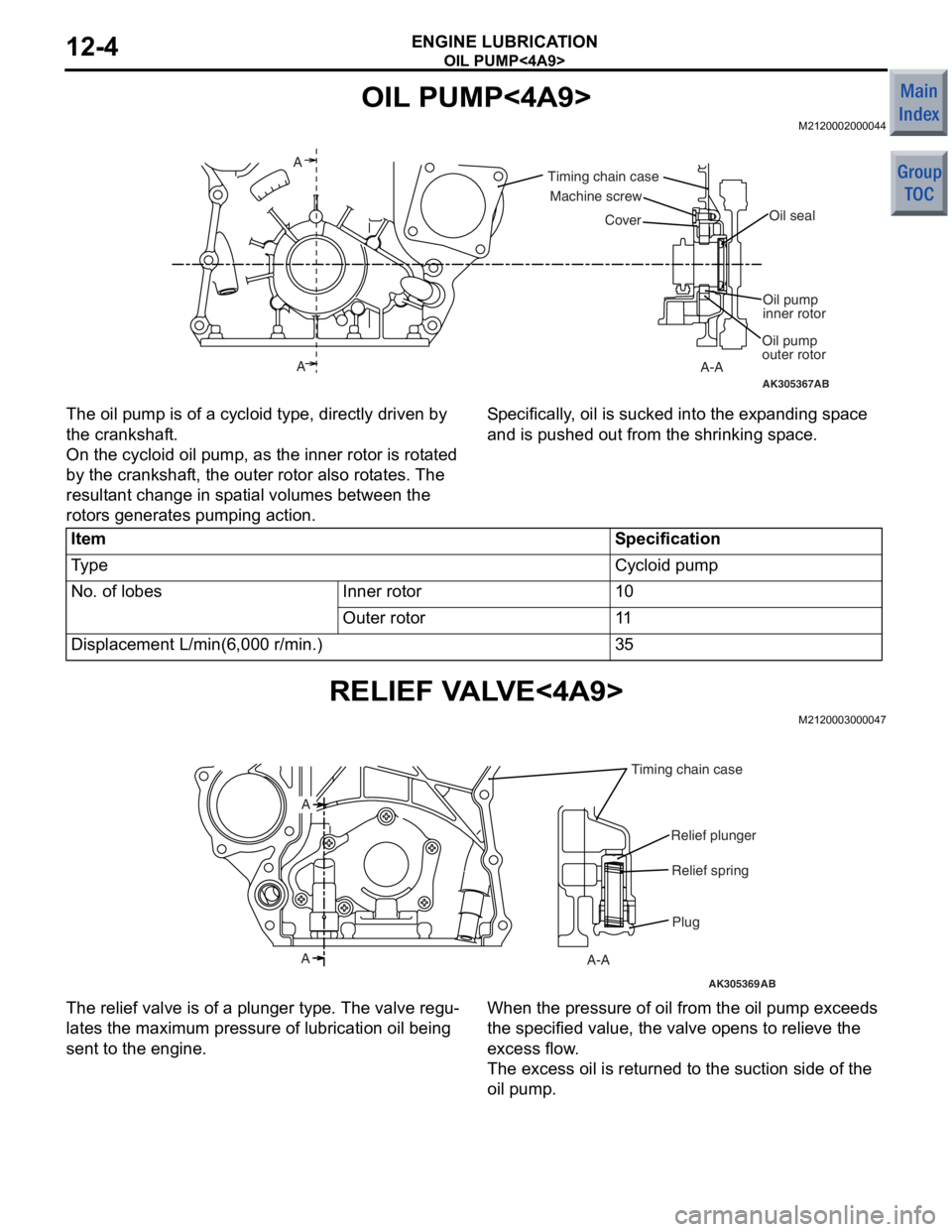
The oil pump is of a
cyclo i d type, d i rectly driven by
the crankshaf
t.
On the cycloid o il p u mp, as th e inn e r rotor is ro t a ted
by th
e cran kshaf t, the o u ter rot o r also rot a tes. The
result
a n t ch ange in sp at ial volu mes betwee n the
rotors
genera t es p u mping action .
Sp e c ifically , o il is sucked into the exp and ing sp ace
and is pushed
out from the shrinking sp ace.
ItemSpecification
Ty p eCycloid pump
No. of lobesInner rotor10
Outer rotor11
Displacement L/min(6,000 r/min.)35
RELIEF V A L V E<4A9>
M21200030 0004 7
AK305369AB
Plug
A-A
A A
Relief spring
Relief plunger
Timing chain case
The relief valve is of a
plun ger type. The valve re gu-
lates the maximum pre ssu re of lubricatio n oil being
sent
to the e ngin e .
When the pressure of oil from the oil p u mp exceeds
the specified
value, the valve o pens to relieve the
excess flow
.
The excess o il is ret u rned t o the suct ion side of the
oil pump
.
Page 92 of 364
OIL SCREEN<4A9>
ENGINE LUBRICATION12-5
OIL SCREEN<4A9>
M2120004000039
AK305372AB
Timing chain case
Oil pan
Oil screen
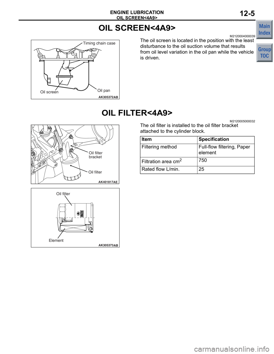
The oil screen is located in the po sition with the lea s t
disturbance to
the oil suction vo lume that result s
from oil
level variat ion in the oil p an while the vehicle
is d
r ive n .
OIL FIL T ER<4A9>
M21200050 0003 2
AK401817AE
Oil filterOil filter
bracket
AK305373
AB
Element
Oil filter
The oil filter is inst alled to the oil filter b r acket
att
a che d to the cylin der block.
ItemSpecification
Filtering methodFull-flow filtering, Paper
element
Filtration area cm2750
Rated flow L/min.25
Page 93 of 364
OIL PAN<4A9>
ENGINE LUBRICATION12-6
OIL PAN<4A9>
M2120006000035
AK305374AB
Oil drain plug
installation side
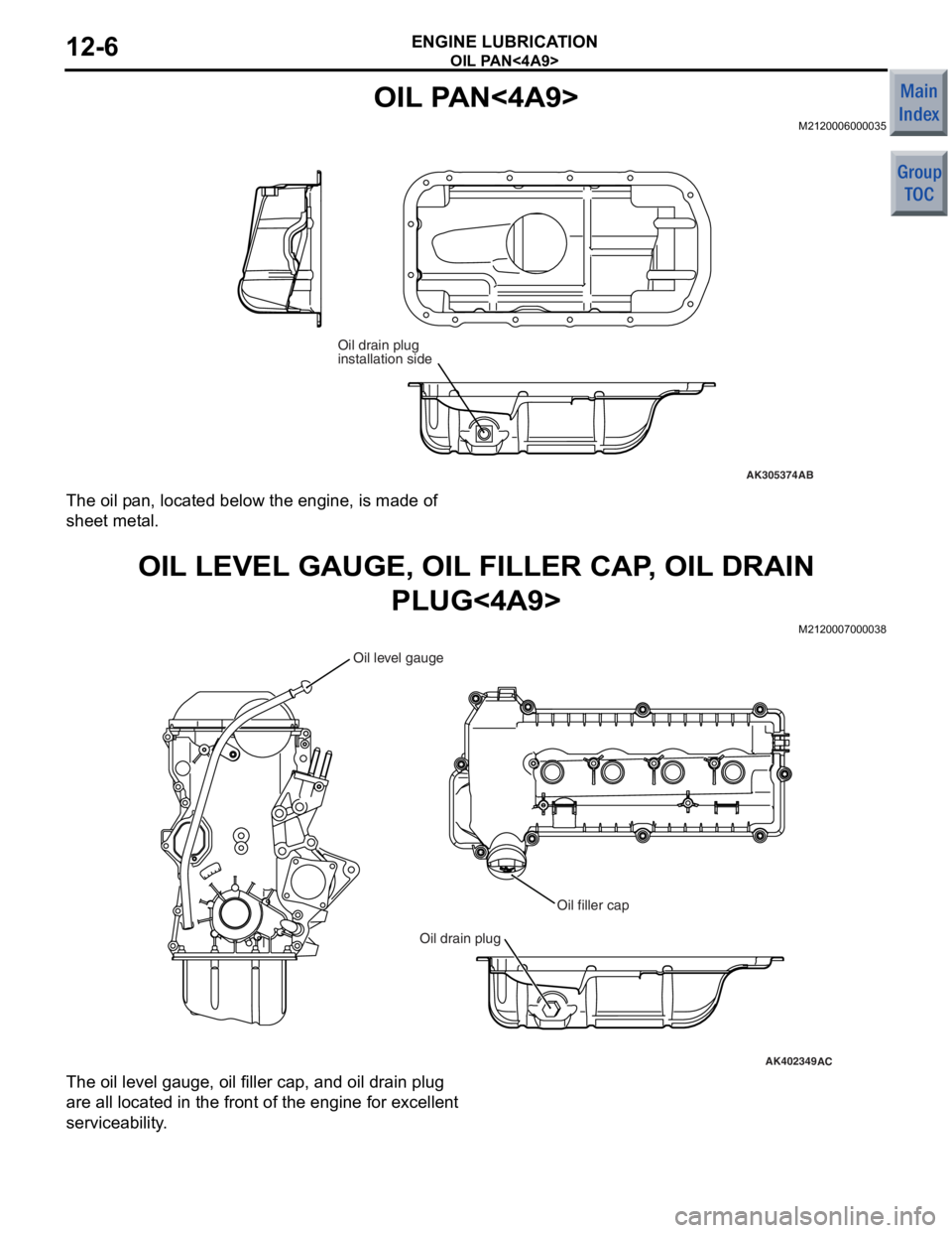
The oil pan, loca ted be low the engin e , is ma de of
shee
t met a l.
OIL LEVEL GAUGE, OIL FILLER CAP , OIL DRAI N
PLUG<4A9>
M21200070 0003 8
AK402349AC
Oil drain plug
Oil filler cap
Oil level gauge
The oil level gauge , oil filler cap, an d oil drain plu g
are all lo
cated in th e front of the engin e for e xce lle nt
service
ability .
Page 94 of 364
OIL COOLER<4G1>
ENGINE LUBRICATION12-7
OIL COOLER<4G1>
M2120008000020
AK402142
Oil outletOil inlet
To cylinder block
From oil filter
Coolant inlet
(from throttle body)
Coolant outlet
(to water inlet pipe)
Oil cooler boltOil cooler
AC
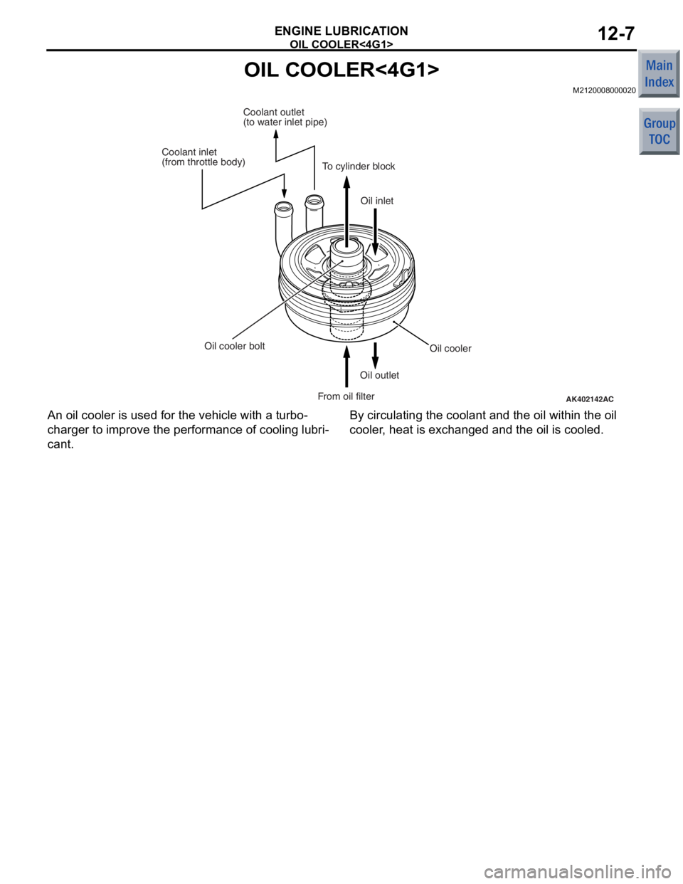
An
oil cooler is used for the vehicle wit h a turb o-
charge r to improve the per formance of cooling lubri-
cant.
By circulating the coolant an d the o il within t he oil
cooler
, he at is exchang ed an d the o il is coole d .
Page 95 of 364
GROUP 13A
MULTIPOINT FUEL INJECTION (MPI)
<4A9>
CONTENTS
GENERAL INFORMATIO N . . . . . . . .13A-2
FUEL INJECTION CONTROL . . . . . .13A-9
THROTTLE VALVE OPENING
ANGLE CONTROL AND IDLE
SPEED CONTROL . . . . . . . . . . . . . . .13A-10
IGNITION TIMING AND
DISTRIBUTION CONTROL . . . . . . . .13A-11
OTHER CONTROL FUNCTIONS . . . .13A-11
FAN RELAY CONTROL . . . . . . . . . . .13A-12
CONTROLLER AREA NETWORK
(CAN) . . . . . . . . . . . . . . . . . . . . . . . . .13A-13
DIAGNOSIS SYSTEM. . . . . . . . . . . . .13A-14
Page 96 of 364

GENERAL INFORMATION
MULTIPOINT FUEL INJECTION (MPI) <4A9>13A-2
GENERAL INFORMATION
M2132000100990
Although the control systems are basically the same
as those of the 4G1-Non-Turbo engine used in the
COLT, the following improvements have been added.
ImprovementRemark
Dual oxygen sensor is used Higher reliability of air-fuel ratio control
Fan relay control is changedAbolish the two stage control of the fan rotating speed.
Page 97 of 364
GENERAL INFORMATION
MULTIPOINT FUEL INJECTION (MPI) <4A9>13A-3
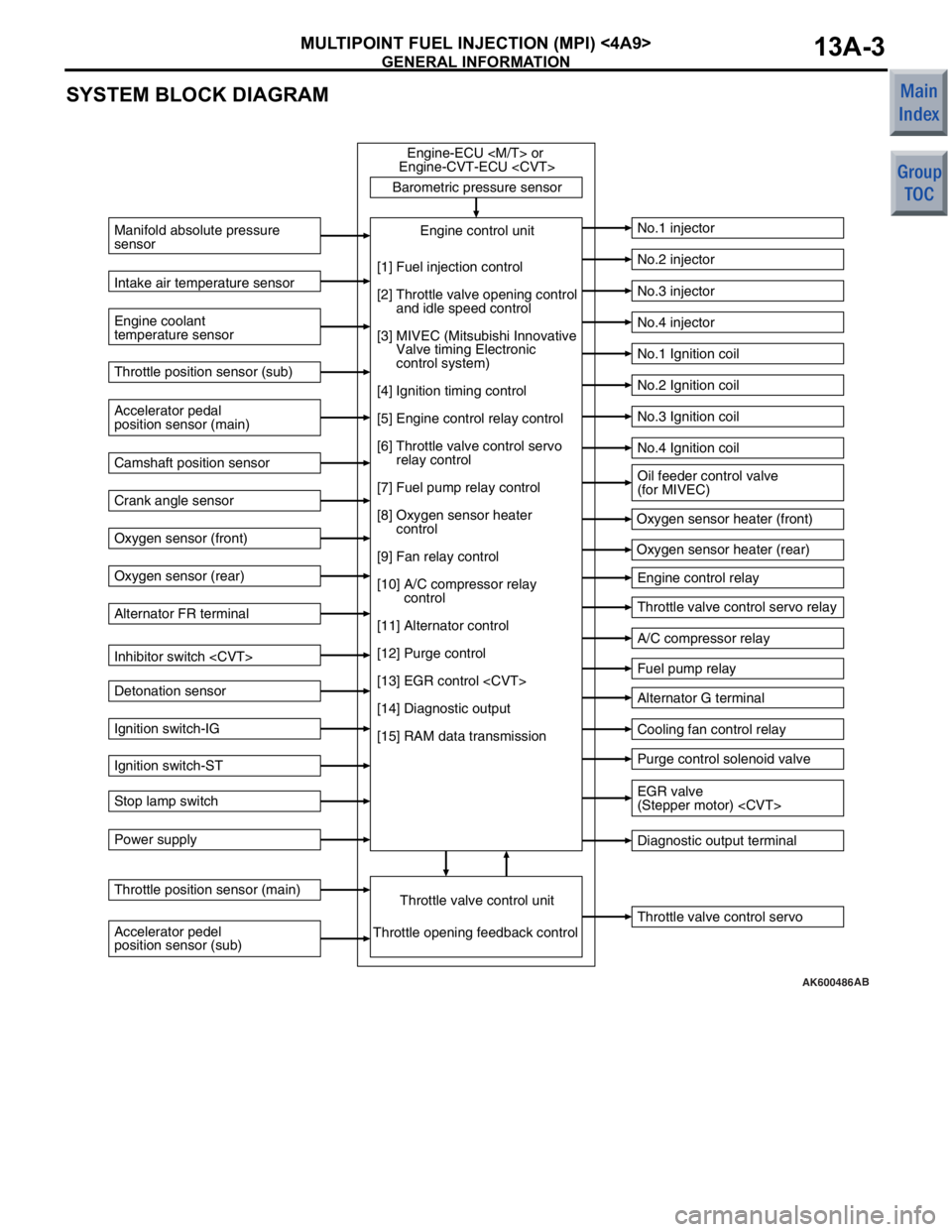
SYSTEM BLOCK DIAGRAM
AK600486
Barometric pressure sensorThrottle valve control servo
Manifold absolute pressure
sensor
Engine coolant
temperature sensor
No.1 injector
No.2 injector
No.3 injector
No.4 injector
No.1 Ignition coil
No.2 Ignition coil
No.3 Ignition coil
No.4 Ignition coil
Engine control relay
Throttle valve control servo relay
A/C compressor relay
Fuel pump relay
Alternator G terminal
Cooling fan control relay
Purge control solenoid valve
Diagnostic output terminal
Intake air temperature sensor
Accelerator pedal
position sensor (main) Throttle position sensor (sub)
Camshaft position sensor
Crank angle sensor
Oxygen sensor (front)
Oxygen sensor (rear)
Alternator FR terminal
Inhibitor switch
Detonation sensor
Ignition switch-IG
Ignition switch-ST
Stop lamp switch
Power supply
Accelerator pedel
position sensor (sub) Throttle position sensor (main)
Throttle valve control unitEngine control unit
Engine-ECU
Engine-CVT-ECU
Throttle opening feedback control Oxygen sensor heater (front)
Oxygen sensor heater (rear)
[1] Fuel injection control
[2] Throttle valve opening control
and idle speed control
[3] MIVEC (Mitsubishi Innovative
Valve timing Electronic
control system)
[4] Ignition timing control
[5] Engine control relay control
[6] Throttle valve control servo
relay control
[7] Fuel pump relay control
[8] Oxygen sensor heater
control
[9] Fan relay control
[10] A/C compressor relay
control
[11] Alternator control
[12] Purge control
[13] EGR control
[14] Diagnostic output
[15] RAM data transmission
Oil feeder control valve
(for MIVEC)
EGR valve
(Stepper motor)
AB
Page 98 of 364
GENERAL INFORMATION
MULTIPOINT FUEL INJECTION (MPI) <4A9>13A-4
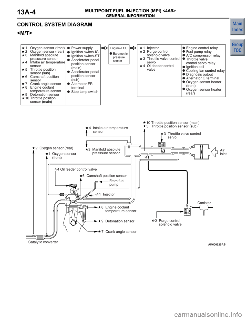
CONTROL SYSTEM DIAGRAM
AK600525
1 Oxygen sensor
(front)4 Intake air temperature
sensor
3 Manifold absolute
presssure sensor
2 Oxygen sensor (rear) 3 Throttle valve control
servo
10 Throttle position sensor
(main)
2 Purge control
solenoid valve
8 Engine coolant
temperature sensor
9 Detonation sensor
7 Crank angle sensor
6 Camshaft position sensor
4 Oil feeder control valve
1 Injector
AB
M
1 Oxygen sensor (front)
2 Oxygen sensor (rear)
3 Manifold absolute
presssure sensor
4 Intake air temperature
sensor
5 Throttle position
sensor
(sub)
6 Camshaft position
sensor
7 Crank angle sensor
8 Engine coolant
temperature sensor
9 Detonation sensor
10 Throttle position
sensor (main) 1 Injector
2 Purge control
solenoid valve
3 Throttle valve control
servo
4 Oil feeder control
valve
Power supply
Ignition switch-IG
Ignition switch-ST
Accelerator pedal
position sensor
(main)
Accelerator pedal
position sensor
(sub)
Alternator FR
terminal
Stop lamp switchEngine-ECUEngine control relay
Fuel pump relay
A/C compressor relay
Throttle valve
control servo relay
Ignition coil
Cooling fan
control relay
Diagnosis output
Alternator G terminal
Oxygen sensor heater
(front)
Oxygen sensor heater
(rear)
Canister Air
inlet
Catalytic converter From fuel
pump
5 Throttle position sensor
(sub)
Barometric
pressure
sensor
Page 99 of 364
GENERAL INFORMATION
MULTIPOINT FUEL INJECTION (MPI) <4A9>13A-5
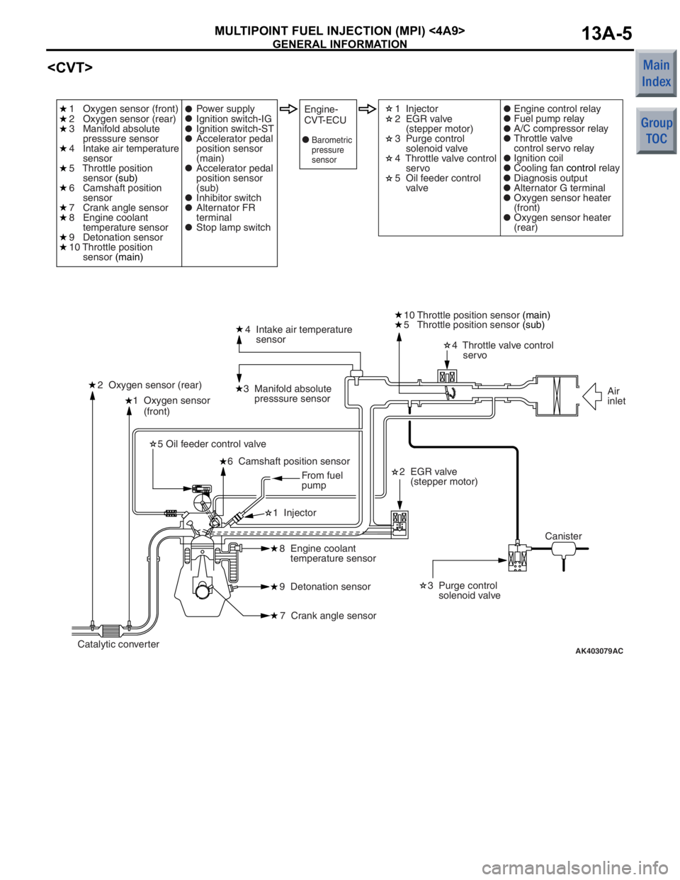
AK403079
1 Oxygen sensor
(front)4 Intake air temperature
sensor
3 Manifold absolute
presssure sensor
2 Oxygen sensor (rear) 4 Throttle valve control
servo
10 Throttle position sensor
(main)
2 EGR valve
(stepper motor) 3 Purge control
solenoid valve
8 Engine coolant
temperature sensor
9 Detonation sensor
7 Crank angle sensor
6 Camshaft position sensor
5 Oil feeder control valve
1 Injector
AC
1 Oxygen sensor (front)
2 Oxygen sensor (rear)
3 Manifold absolute
presssure sensor
4 Intake air temperature
sensor
5 Throttle position
sensor (sub)
6 Camshaft position
sensor
7 Crank angle sensor
8 Engine coolant
temperature sensor
9 Detonation sensor
10 Throttle position
sensor (main) 1 Injector
2 EGR valve
(stepper motor)
3 Purge control
solenoid valve
4 Throttle valve control
servo
5 Oil feeder control
valve
Power supply
Ignition switch-IG
Ignition switch-ST
Accelerator pedal
position sensor
(main)
Accelerator pedal
position sensor
(sub)
Inhibitor switch
Alternator FR
terminal
Stop lamp switchEngine-
CVT-ECUEngine control relay
Fuel pump relay
A/C compressor relay
Throttle valve
control servo relay
Ignition coil
Cooling fan
control relay
Diagnosis output
Alternator G terminal
Oxygen sensor heater
(front)
Oxygen sensor heater
(rear)
Canister Air
inlet
Catalytic converter From fuel
pump
5 Throttle position sensor
(sub)
Barometric
pressure
sensor
Page 100 of 364

GENERAL INFORMATION
MULTIPOINT FUEL INJECTION (MPI) <4A9>13A-6
List of Component Functions
NameFunction
ECU
Engine-ECU
actuators to be controlled in accordance with the
driving conditions.
Sensors
Ignition switch-IGThis signal indicates the ON/OFF condition of the
ignition switch. When this signal is input, the
engine-ECU
supplies power to the crank angle sensor, camshaft
position sensor, etc.
Ignition switch-STThis signal indicates that the engine is cranking.
Based on this signal, the engine-ECU
engine-CVT-ECU
throttle valve position, and the injection timing that
are suited for starting the engine.
Manifold absolute pressure sensor Uses a pressure conversion element to detect the
pressure in the intake manifold, converts it into a
voltage signal, and outputs it to the
engine-ECU
engine-ECU
optimally corrects the fuel injection amount and the
like based on this signal.
Oxygen sensor
electrodes, detects the level of oxygen concentration
in the exhaust gases. The engine-ECU
engine-CVT-ECU
air-fuel ratio is at the optimal stoichiometric ratio in
accordance with this oxygen concentration level.
Barometric pressure sensorThis sensor detects the altitude of the vehicle. It
enables the engine-ECU
order to achieve an appropriate air-fuel ratio.
Intake air temperature sensorThis sensor, which contains a thermistor, detects the
temperature of the intake air. The engine-ECU
or engine-CVT-ECU
volume corrections that suit the intake air
temperature, in accordance with the voltage that is
output by this sensor.
Engine coolant temperature sensorThis sensor, which contains a thermistor, detects the
temperature of the engine coolant. The engine-ECU
warm-up condition of the engine in accordance with
the voltage that is output by this sensor, in order to
control the fuel injection volume, idle speed, and
ignition timing.