MITSUBISHI COLT 2006 Service Repair Manual
Manufacturer: MITSUBISHI, Model Year: 2006, Model line: COLT, Model: MITSUBISHI COLT 2006Pages: 364, PDF Size: 11.65 MB
Page 151 of 364
MAIN BODY
BODY42-8
AB600121
AB400213
AD
1
2
Rear pillar inner reinforcementRear wheel house inner gusset
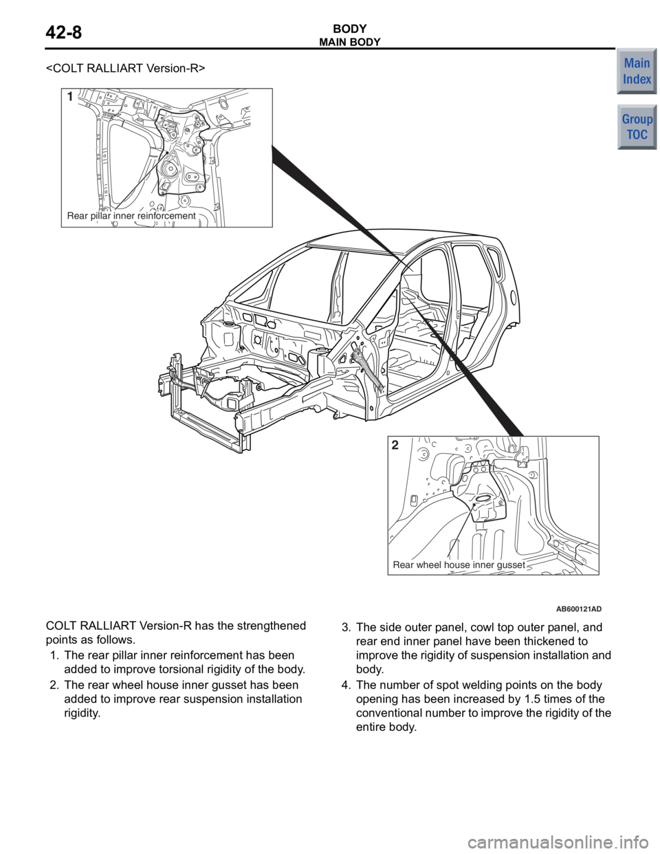
COLT RAL L IAR T V e rsion-R h a s th e stre ngthen ed
point
s as fo llo ws.
1.The rear pilla r inne r reinf o rcement h a s b een
add ed to impro v e to rsional rigid i ty of the body .
2.The rear whee l hou se inner gu sset has been
add ed to impro v e re ar su spen sio n inst a lla tion
rigidity .
3.The sid e oute r p a nel, cowl t op oute r p anel, and
rear end inner p ane l have be en thickened to
imp r ove the rigidity of suspe n sion inst allat i o n a n d
bod y .
4.The number of spot welding poin t s on th e body
ope ning has been incre a sed by 1 . 5 times of the
co nve n t i on al n u mb er t o imp r o v e th e ri gid i t y o f th e
ent ire bo dy .
Page 152 of 364
MAIN BODY
BODY42-9
QUIETNESS
M2420004000416
AB201000
AB400213
12
3
2
AB
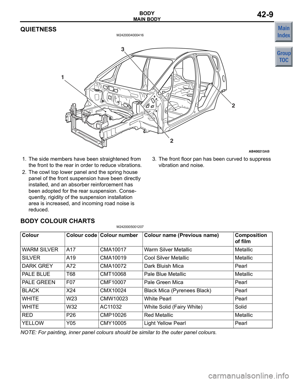
1.The sid e me mbers have bee n stra ighte ned fro m
the front to the rea r in o r der to r educe vibratio ns.
2.The cowl t op lo we r p a nel a nd the spring ho use
p anel of the front suspension h a ve b een direct ly
in st alled, an d an ab sorbe r rein forcement has
bee n adop ted for the rea r suspension . Conse
-
quently , rigid i ty of the suspension inst allation
area
is increase d , and incoming roa d noise is
redu
ced.
3.The front floor p an has b een curve d to suppress
vibration an d noise.
BODY COLOUR CHARTS
M24200050 0120 7
ColourColour codeColour numberColour name (Previous name)Composition
of film
WARM SILVERA17CMA10017Warm Silver MetallicMetallic
SILVERA19CMA10019Cool Silver MetallicMetallic
DARK GREYA72CMA10072Dark Bluish MicaPearl
PA L E B L U ET68CMT10068Pale Blue MetallicMetallic
PALE GREENF07CMF10007Pale Green MicaPearl
BLACKX24CMX10024Black Mica (Pyrenees Black)Pearl
WHITEW23CMW10023White PearlPearl
WHITEW32AC11032White Solid (Fairy White)Solid
REDP26CMP10026Red MetallicMetallic
YELLOWY05CMY10005Light Yellow PearlPearl
NOTE: For p a intin g , in ner p anel colours sho u ld b e similar to t he oute r p anel colours.
Page 153 of 364
HOOD <4G1>
BODY42-10
HOOD <4G1>
M2420023000404
AC601510 AB
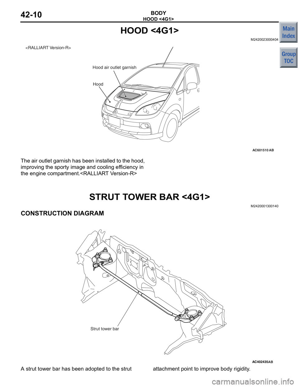
Hood air outlet garnish
The air ou
tlet ga rnish has be en inst alle d to the hoo d,
imp
r oving the sport y image and cooling ef ficiency in
the eng
ine comp a r tment .
STRUT TO WER BAR <4G1>
M24200013 0014 0
CONSTRUCTION DIAGRAM
AC402435AB
Strut tower bar
A strut to we r bar ha s be en ado pted to the strut att a chment p o int t o improve body rigidity .
Page 154 of 364
DOOR
BODY42-11
DOOR
DOOR LOCKM2420009000499
CENTRAL DOOR LOCKING
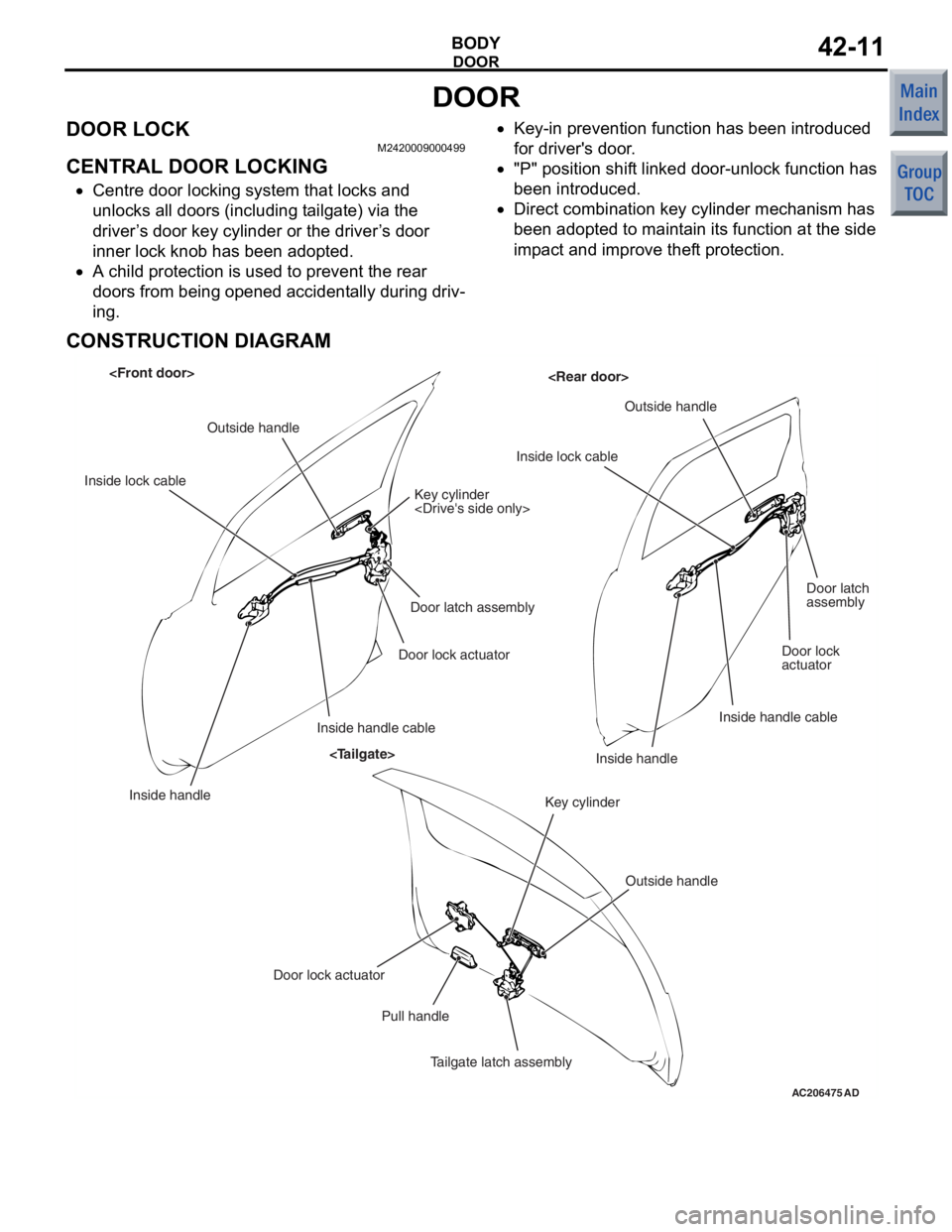
•Centre door locking system that locks and
unlocks all doors (including tailgate) via the
driver’s door key cylinder or the driver’s door
inner lock knob has been adopted.
•A child protection is used to prevent the rear
doors from being opened accidentally during driv
-
ing.
•Key-in prevention function has been introduced
for driver's door.
•"P" position shift linked door-unlock function has
been introduced.
•Direct combination key cylinder mechanism has
been adopted to maintain its function at the side
impact and improve theft protection.
CONSTRUCTION DIAGRAM
AC206475 AD
Outside handle
Inside lock cable Key cylinder
Door latch assembly
Door lock actuator
Inside handle cable
Inside handle Inside lock cable
Outside handle
Door latch
assembly
Door lock
actuator
Inside handle cable
Inside handle
Door lock actuator Pull handle
Tailgate latch assembly Key cylinder
Outside handle
Page 155 of 364
DOOR
BODY42-12
DESCRIPTION OF STRUCTURE AND
OPERATION
CENTRAL DOOR LOCKING
•When the driver's door inner lock knob is oper-
ated to the lock position with all doors closed, all
the doors (including tailgate) will lock.
•The driver’s door can be opened by pulling the
driver’s door inner handle even when the driver’s
door inner lock knob is in the lock position. This
function is called "Override function". All doors
and tailgate can be unlocked at the same time
that the driver's door is opened.
KEY-IN PREVENTION FUNCTION
If the driver’s door remained open, it cannot be
locked even though the driver’s door key cylinder or
driver’s side inside lock knob is pushed. This pre
-
vents the ignition key from being left in the passenger
compartment.
"P" POSITION SHIFT LINKED
DOOR-UNLOCK FUNCTION
When the selector lever is shifted to the "P" (parking)
position, all the doors (including tailgate) will unlock,
improving passengers' conv enience during alighting.
Using an adjustment function*, "P" position shift
linked door-unlock function can be changed to
"Active", or "Inactive". The initial setting at factory is
"Inactive".
NOTE: *: "P" position shift linked door-unlock func-
tion can be changed as a customise function. Refer
to GROUP 54B, Customise Function
P.54B-25.
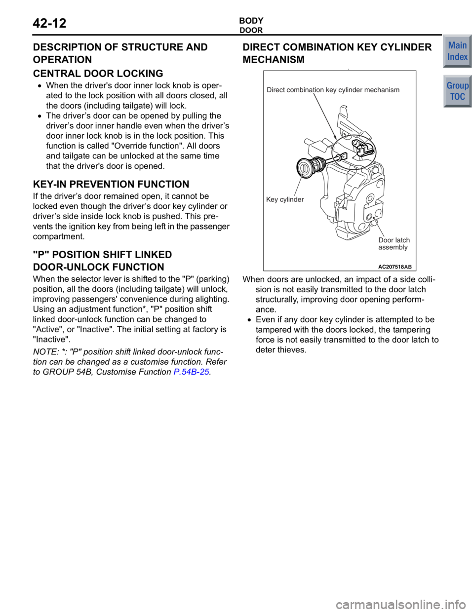
DIRECT COMBINATION KEY CYLINDER
MECHANISM
•
AC207518AB
Door latch
assembly
Key cylinder Direct combination key cylinder mechanism
When d
oors a r e unlocked, a n imp a ct of a side colli-
sion is not easily transmitted to the do or lat c h
structu
r ally , imp r oving do or open ing p e rform
-
ance.
•Even if a n y d oor ke y cylinder is a ttemp ted to b e
t
a mp ered wit h the d oors locked, t he t a mp ering
force is not
easily transmitt ed to t he doo r latch to
det
er thie ves.
Page 156 of 364
DOOR
BODY42-13
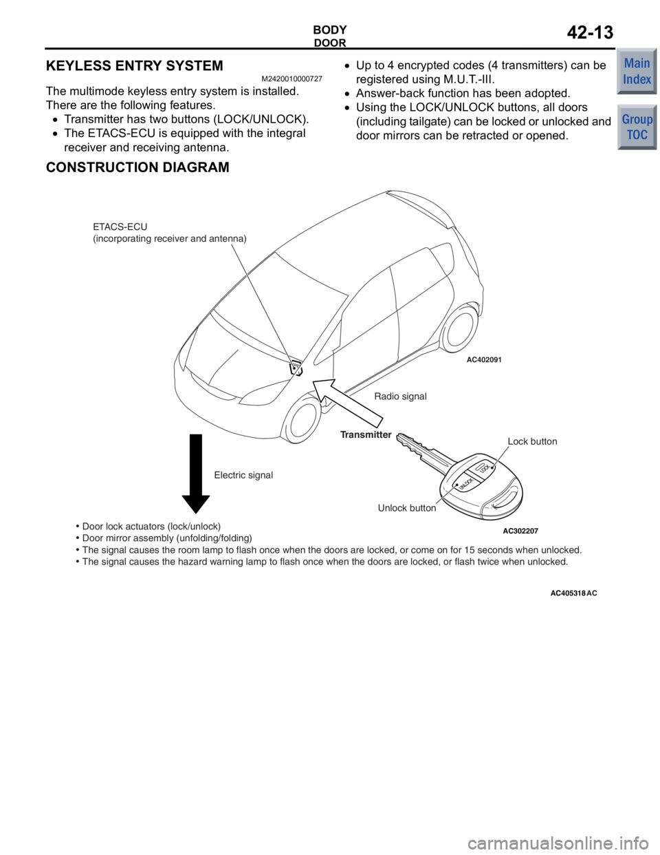
KEYLESS ENTRY SYSTEM
M2420010000727
The multimode keyless entry system is installed.
There are the following features.
•Transmitter has two buttons (LOCK/UNLOCK).
•The ETACS-ECU is equipped with the integral
receiver and receiving antenna.
•Up to 4 encrypted codes (4 transmitters) can be
registered using M.U.T.-III.
•Answer-back function has been adopted.
•Using the LOCK/UNLOCK buttons, all doors
(including tailgate) can be locked or unlocked and
door mirrors can be retracted or opened.
CONSTRUCTION DIAGRAM
AC405318
AC206461
AC302207
AC402091
AC
ETACS-ECU
(incorporating receiver and antenna)
Electric signal Radio signal
Lock button
Unlock button
Transmitter
• Door lock actuators (lock/unlock)
• Door mirror assembly (unfolding/folding)
• The signal causes the room lamp to flash once when the doors are locked\
, or come on for 15 seconds when unlocked.
• The signal causes the hazard warning lamp to flash once when the doors \
are locked, or flash twice when unlocked.
Page 157 of 364
DOOR
BODY42-14
DESCRIPTION OF STRUCTURE AND
OPERATION
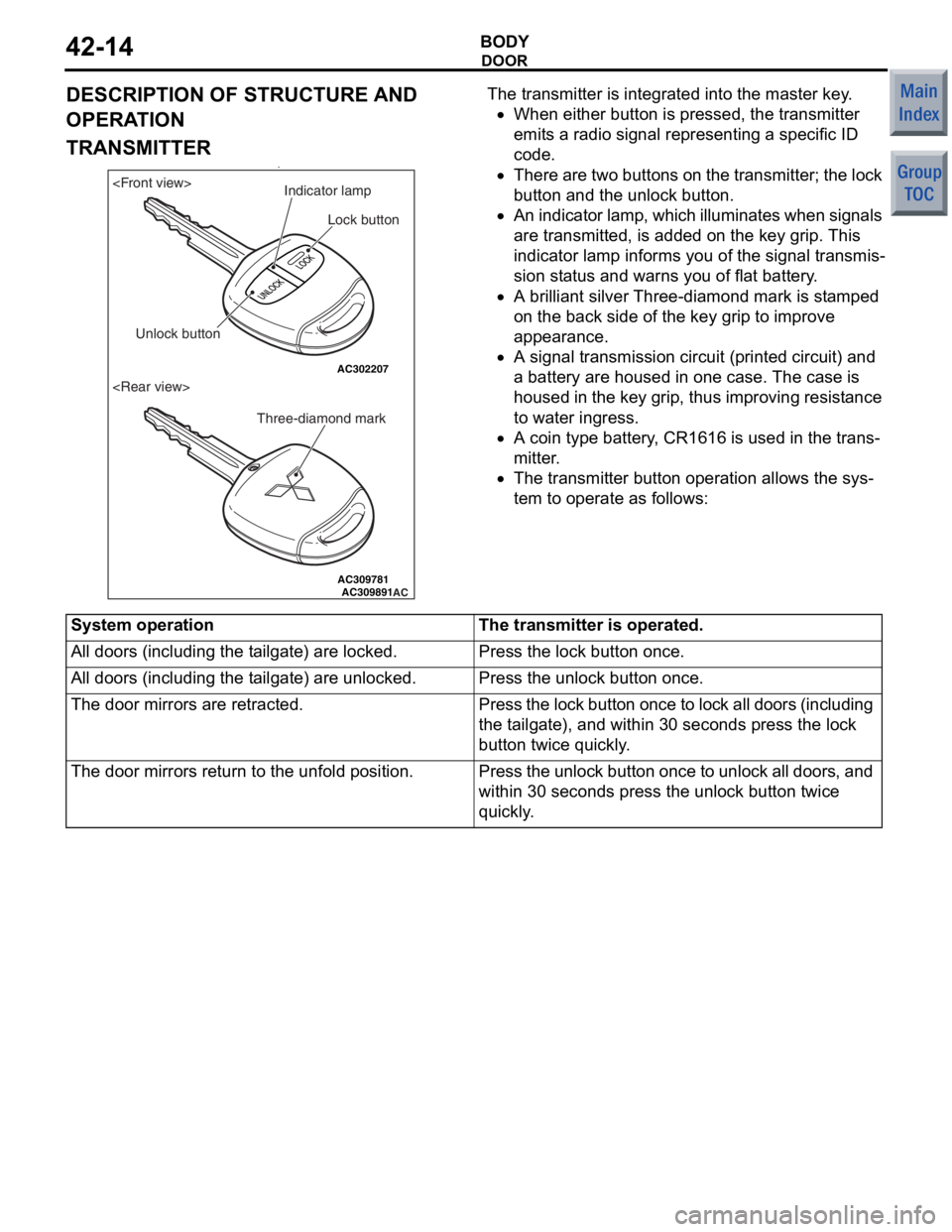
TRANSMITTER•
AC309781 AC309891
AC302207AC
Lock button
Unlock button Three-diamond markIndicator lamp
The tran
smitter is integra t ed in to the master key .
•When eit her butt on is pressed , the tra n smitter
emit
s a radio sig nal re prese n ting a sp ecific ID
code.
•There a r e two butto ns o n th e tra n smitte r; th e lo ck
but
ton and the u n lock bu tton.
•An indicator lamp, which illumina tes when signals
are
transmitt ed, is add ed on t he ke y grip. This
in
dicator lamp informs you of the signa l transmis
-
sion sta t us a nd warns you of flat batt e ry .
•A brilliant silver Three -d ia mond mark is st amped
on
the back side of the key grip to improve
app
earance.
•A signal transmissi on circuit (p rinted circuit ) and
a b
a ttery are ho used in on e ca se. T he ca se is
hou
sed in the key grip, thus improving re sist ance
to wat
e r ing r ess.
•A coin type b a ttery , CR1616 is used in th e trans-
mitter.
•The transmit t er butto n ope ration allows the sys-
tem to operate a s follows:
System operationThe transmitter is operated.
All doors (including the tailgate) are locked.Press the lock button once.
All doors (including the tailgate) are unlocked.Press the unlock button once.
The door mirrors are retracted.Press the lock button once to lock all doors (including
the tailgate), and within 30 seconds press the lock
button twice quickly.
The door mirrors return to the unfold position.Press the unlock button once to unlock all doors, and
within 30 seconds press the unlock button twice
quickly.
Page 158 of 364
DOOR
BODY42-15
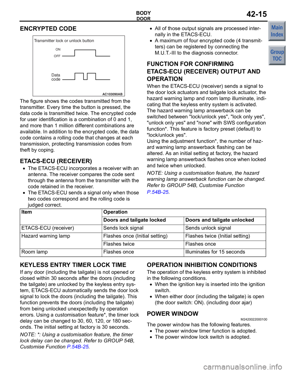
ENCRYPTED CODE
AC103090AB
ON
OFF
Transmitter lock or unlock button
Data
code
The figure shows th e co des transmitte d from the
transmitte
r . Every time the butto n is pressed, the
dat
a cod e is transmitted tw ice. Th e encrypte d co de
for user ide
n tification is a comb ination o f 0 and 1,
and more tha
n 1 million dif f erent comb inations are
available. In a
ddition to t he encrypt ed co de, the dat a
code
cont ains a rolling code t hat change s at e a ch
transmission, prot
ecting tran smission code s from
thef
t by coping.
ETACS-ECU (RECEIVER)
•The ET ACS-ECU incorp orates a receiver with a n
ant
enna. T he receiver co mp ares the code sent
thro
ugh t he an tenna from the transmit t er with the
co
de ret a ined in the re ceiver .
•The ET ACS-ECU send s a si gnal only whe n t hose
two codes corre
spon d and the rollin g co de is
ju
dged correct.
•All of tho s e o u tput sign als are processed inter-
nally in the ETACS-ECU.
•A maximum of fou r encr y pted cod e (4 tran smit-
ters) can be re gistered by co nnecting the
M.U.
T . -III t o the d i agn osis co nnector .
FUNCTION FOR CONFIRMING
ET
ACS-ECU (RECEIVER) OUT P UT AND
OPERA
T ION
When the ET ACS-ECU (receiver) send s a sign al to
the
do or lock actua t o r s an d t a ilga te lo ck actua t or , t h e
haza
r d warnin g lamp an d room lamp illumina te, in di
-
cating that the keyless ent ry syste m is activated.
The hazard warn ing lamp answe rback ca n be
switched b
e tween "lock/unlock yes", "lock o n ly yes",
"unlock o
n ly yes" and "non e" with SW S co nfigurat ion
funct
i on*. Th is f eature is fa ctory preset (de f ault ) to
"lock/unlock ye
s".
Using the ad justment function*, th e number of haz-
ard warning lamp a n swerba ck flashing can be
altere
d. As a n initial set t ing a t factory , the haza r d
wa
rnin g lamp an swerb a ck flashes once wh en locked
and twice when
unlo cke d.
NOTE: Using a cust omisation fea t ure, th e hazard
wa
rning lamp answe rback fun c tio n ca n be change d.
Re
fer to GROUP 54B, Customise Function
P.54B-25.
ItemOperation
Doors and tailgate lockedDoors and tailgate unlocked
ETACS-ECU (receiver)Sends lock signalSends unlock signal
Hazard warning lampFlashes once (I nitial setting)Flashes twice (Initial setting)
Flashes twiceFlashes once
Room lampFlashes onceIlluminates for 15 seconds
KEYLESS ENTR Y TIMER LOCK TIME
If any door (includin g the t a ilgat e) is not op ened or
closed within 3
0 se cond s af ter th e doo rs (in c lu ding
the t
a ilgate) a r e unlocked by the keyless ent ry sys
-
tem, ETACS-ECU aut omatically sen d s th e door lock
sign
al to lock the doors (includ i ng t he t a ilgate). T h is
funct
i on p r even t s the d oors (including the t a ilga te)
from b
e ing unlocke d unex pectedly by opera t ion
errors.
Using a customisa t ion fea t ure*, the timer lock
delay ca
n be chang ed to 3 0 , 60, 120, or 180 sec
-
onds. The initial setting at fa ctory is 30 secon d s.
NOTE: *: Using a custo m isation fea t ure, the timer
lock delay can b e ch anged. Re fer to GROUP 54B,
Customise Function
P.54B-25.
OPERA T ION INHIBITION CONDITIONS
The operation of t he keyless entry system is inhibited
in the
following cond itio ns.
•When the ignition key is inse rted into the ignition
sw
itc h .
•When eit her doo r (including th e t a ilg ate) is ope n
(the
door switch : ON). (includin g doo r ajar)
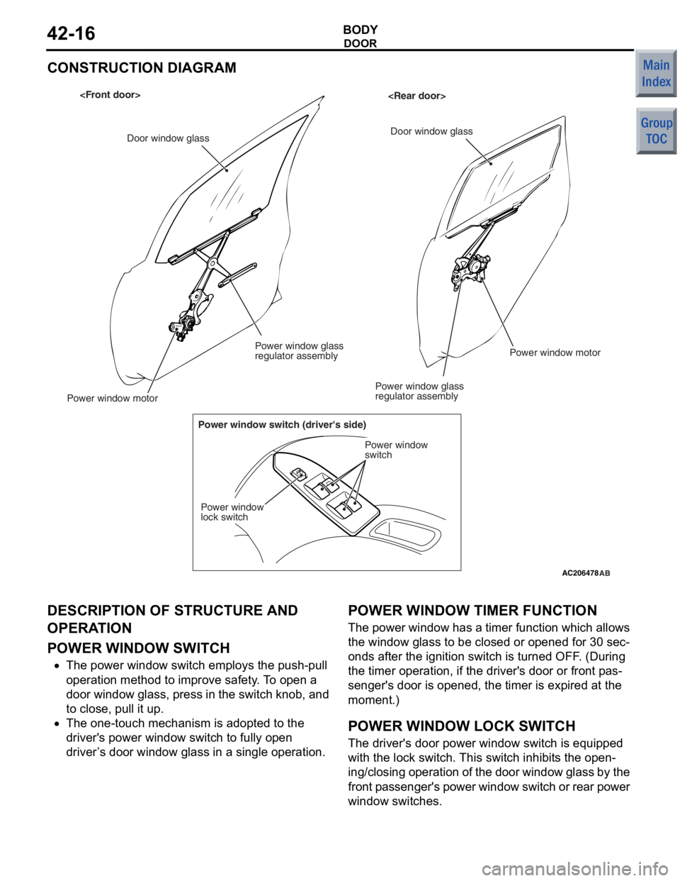
POWER WI NDOW
M24200220 0010 0
The powe r window ha s the following f eatures.
•The power wind ow timer functio n is adopt ed.
•The power wind ow lock switch is adopte d .
Page 159 of 364
DOOR
BODY42-16
CONSTRUCTION DIAGRAM
AC206478AB
Door window glass Door window glass
Power window motor
Power window glass
regulator assembly
Power window glass
regulator assembly
Power window motor
Power window switch (driver's side) Power window
switch
Power window
lock switch
DESCRIPTION OF STRUCTURE AND
OPERA
T ION
POWE R W I NDOW SWITCH
•The power wind ow switch employs t he push-pull
ope
ration meth od to imp r ove safety . T o o pen a
doo
r windo w glass, p r ess in the switch kno b , and
to close, pu
ll it up.
•The one-to uch mechanism is a dopted to the
driver's power win
dow swit ch to fully op en
driver
’ s door win dow gla s s in a sin g le o peration.
POWER WI NDOW TIMER FUNCTION
The po wer wind ow has a t i me r function which allows
the wind
ow glass t o be closed or o pened for 30 sec
-
onds after the ignition switch is turned OFF . (Durin g
the timer o
peration, if the driver's doo r or fron t p a s
-
senger's d oor is open ed, th e timer is expired at the
moment.)
POWER WI NDOW LOCK SWITCH
The driver's door power wind ow switch is equ ipped
with the
lock switch. This swit ch inhib i t s the open
-
ing/ clos ing ope ra tio n o f t h e do or wind ow gl ass b y t he
f
r ont p a ssenger's power window switch or rear power
window switche
s .
Page 160 of 364
PROTECTOR FILM
BODY42-17
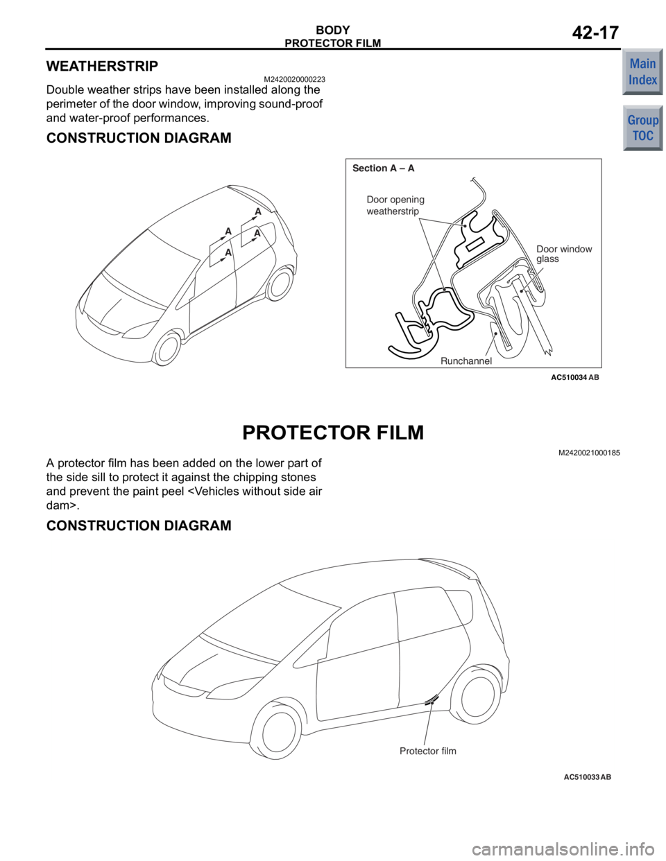
WEATHERSTRIP
M2420020000223
Double weather strips have been installed along the
perimeter of the door window, improving sound-proof
and water-proof performances.
CONSTRUCTION DIAGRAM
AC510034AB
AA A
A
Door opening
weatherstrip
Door window
glass
Runchannel
Section A – A
PROTECT
O R FILM
M24200210 0018 5
A pr otector film h a s be en ad ded on the lower p a rt of
the side sill to pr
otect it ag ainst the chip ping ston es
and p
r even t the p a int peel
CONSTRUCTION DIAGRAM
AC510033AB
Protector film