ECO mode MITSUBISHI DIAMANTE 1900 User Guide
[x] Cancel search | Manufacturer: MITSUBISHI, Model Year: 1900, Model line: DIAMANTE, Model: MITSUBISHI DIAMANTE 1900Pages: 408, PDF Size: 71.03 MB
Page 45 of 408
.
I-46 GENERALINFORMATIONAND MAINTENANCE
2. Pull the jumping vehicle (with the good bat-
tery) into a position so the jumper cables can reach
the dead battery and that vehicle’s engine. Make sure
that the vehicles do NOT touch.
3. Place the transmissions/transaxles of both ve-
hicles in Neutral (MT) or P (AT), as applicable, then
firmly set their parking brakes.
*ff necessary for safety reasons, the hazard
lights on both vehicles may be operated
throughout the entire procedure without sig-
nificantiy increasing the diff icuity of jumping
the dead battery.
4. Turn all lights and accessories OFF on both
vehicles. Make sure the ignition switches on both ve-
hicles are turned to the OFF position.
5. Cover the battery cell caps with a rag, but do
not cover the terminals.
6. Make sure the terminals on both batteries are
clean and free of corrosion or proper electrical con-
nection will be impeded. If necessary, clean the bat-
tery terminals before proceeding.
7. Identify the positive (+) and negative (-) termi-
nals on both batteries.
8. Connect the first jumper cable to the positive
(t) terminal of the dead battery, then connect the
other end of that cable to the positive (t) terminal of
the booster (good) battery.
9. Connect one end of the other jumper cable to
the negative (−) terminal on the booster bat-
tery and the final cable clamp to an engine bolt head,
alternator bracket or other solid, metallic point on the
engine with the dead battery. Try to pick a ground on
the engine that is positioned away from the battery in
order to minimize the possibility of the 2 clamps
touching should one loosen during the procedure.
DO NOT connect this clamp to the negative (-) termi-
nal of the bad battery. cable on the donor battery. Disconnect the positive
cable from the donor battery and finally, disconnect
the positive cable from the formerly dead battery. Be
careful when disconnecting the cables from the posi-
tive terminals not to allow the alligator clips to touch
any metal on either vehicle or a short and sparks will
occur.
I
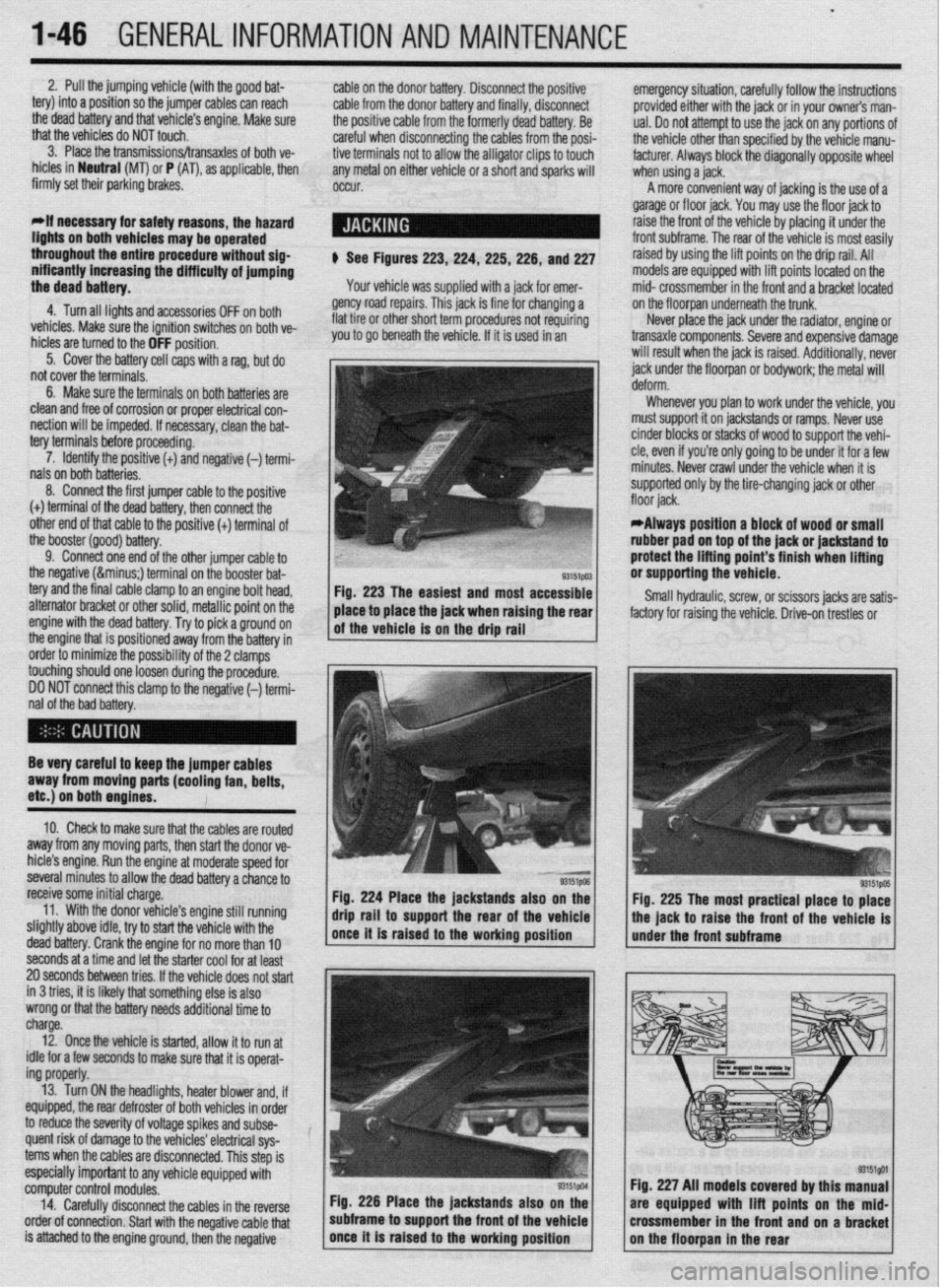
$ See Figures 223,224, 225,226, and 227
Your vehicle was supplied with a jack for emer-
gency road repairs. This jack is fine for changing a
flat tire or other short term procedures not requiring
you to go beneath the vehicle. If it is used in an emergency situation, carefully follow the instructions
provided either with the jack or in your owners man-
ual. Do not attempt to use the jack on any portions of
the vehicle other than specified by the vehicle manu-
facturer. Always block the diagonally opposite wheel
when using a jack.
A more convenient way of jacking is the use of a
garage or floor jack. You may use the floor jack to
raise the front of the vehicle by placing it under the
front subframe. The rear of the vehicle is most easily
raised by using the lift points on the drip rail. All
models are equipped with lift points located on the
mid- crossmember in the front and a bracket located
on the floorpan underneath the trunk.
Never place the jack under the radiator, engine or
transaxle components. Severe and expensive damage
will result when the jack is raised. Additionally, never
jack under the floorpan or
bodywork; the
metal will
Whenever you plan to work under the vehicle, you
must support it on jackstands or ramps. Never use
cinder blocks or stacks of wood to support the vehi-
cle, even if you’re only going to be under it for a few
minutes. Never crawl under the vehicle when it is
supported only by the tire-changing jack or other
*Always position a block of wood or small
rubber pad on top of the jack or jackstand to
protect the lifting point’s finish when lifting
or supporting the vehicle.
Small hydraulic, screw, or scissors jacks are satis-
factory for raising the vehicle. Drive-on trestles or
Be very careful to keep the jumper cables
away from moving parts (cooling fan, belts,
etc.) on both engines.
10. Check to make sure that the cables are routed
away from any moving parts, then start the donor ve-
hicle’s engine. Run the engine at moderate speed for
several minutes to allow the dead battery a chance to
receive some initial charge.
11. With the donor vehicle’s engine still running
slightly above idle, try to start the vehicle with the
dead battery. Crank the engine for no more than 10 &stands also on the
Fig. 225 The most practical place to place
front of the vehicle is
seconds at a time and let the starter cool for at least
20 seconds between tries. If the vehicle does not start
in 3 tries, it is likely thatsomething else is also
wrong or that the battery needs additional time to
charge.
12. Once the vehicle is started, allow it to run at
idle for a few seconds to make sure that it is operat-
ing properly.
13. Turn ON the headlights, heater blower and, if
equipped, the rear defroster of both vehicles in order
to reduce the severity of voltage spikes and subse-
quent risk of damage to the vehicles’ electrical sys-
tems when the cables are disconnected. This step is
especially important to any vehicle equipped with
computer control modules.
14. Carefully disconnect the cables in the’reverse
order of connection. Start with the negative cable that
is attached to the engine ground, then the negative Fig. 226 Place the jackstands also
subframe to support the front of the Fig. 227 All models covered by this
are equipped with lift points on t
crossmember in the front and on a
Page 56 of 408
ENGlNEELECTRldAL 2-9
TESTING
Voltage Test able for use by customers. An alternator
bench test is the most definitive way to de-
termine the condition of your alternator.
REMOVAL&INSTALLATION
1. Make sure the engine is OFF, and turn the 1.51,1.61, 1.6L, 2.OL and 2.4L Engines
headlights on for 15-20 seconds to remove any sur-
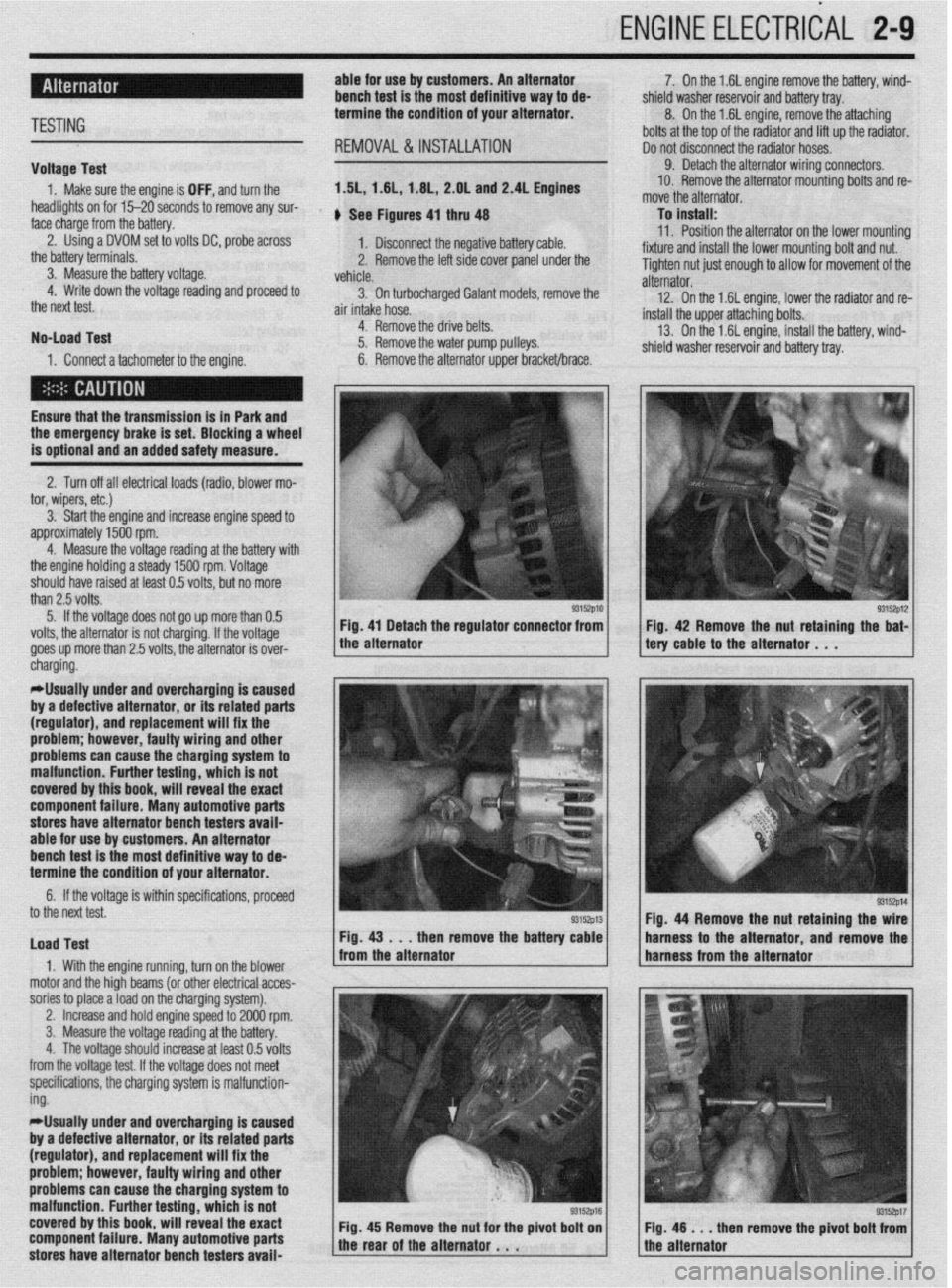
face charge from the battery. , See Figures 4, thru 48
2. Using a DVOM set to volts DC, probe across
1. Disconnect the negative battery cable.
the battery terminals.
3. Measure the battery voltage. 2. Remove the left side cover panel under the
vehicle.
4. Write down the voltage reading and proceed to
3. On turbocharaed Galant models, remove the
the next test.
air intake hose. -
No-load Test
1. Connect a tachometer to the engine. 4. Remove the drive belts.
5. Remove the water pump pulleys.
6. Remove the alternator upper bracket/brace.
Ensure that the transmission
is in Park and the emergency brake is set. Blocking a wheel
is optional and an added safety measure.
2. Turn off all electrical loads (radio, blower mo-
tor, wipers, etc.)
3. Start the engine and increase engine speed to
approximately 1500 rpm.
4. Measure the voltage reading at the battery with
the engine holding a steady 1500 rpm. Voltage
should have raised at least 0.5 volts, but no more
than 2.5 volts.
5. If the voltage does not go up more than 0.5
volts, the alternator is not charging. If the voltage
goes up more than 2.5 volts, the alternator is over-
* 7. On the 1.6L engine remove the battery, wind-
shield washer reservoir and battery tray.
8. On the 1.6L engine, remove the attaching
bolts at the top of the radiator and lift up the radiator.
Do not disconnect the radiator hoses.
9. Detach the alternator wiring connectors.
10. Remove the alternator mounting bolts and re-
move the alternator.
To install:
11. Position the alternator on the lower mountina
fixture and install the lower mounting bolt and nut. U
Tighten nut just enough to allow for movement of the
alternator.
12. On the 1.6L engine, lower the radiator and re-
install the upper attaching bolts.
13. On the 1.6L engine, install the battery, wind-
shield washer reservoir and battery tray.
/ tery cable to the alternator . , . 93152p12 Fig 42 Remove the nut retaining the bat-
cnargmg.
*Usually under and overcharging is‘caused
by a defective alternator, or its related parts
(regulator), and replacement will fix the
problem; however, faulty wiring and other
problems can
cause the charging system to
malfunction. Further testing, which is not
covered by this book, will reveal the exact
component failure. Many automotive parts
stores have alternator bench testers avaii-
able for use by customers. An alternator
bench test is the most definitive way to de-
termine the condition of your alternator.
6. If the voltage is within specifications, proceeU
to the next test.
Load Test
1. With the engine running, turn on the blower
motor and the hioh beams (or other electrical acces-
sories to place aioad on the charging system). Fig. 44 Remove the nut retaining the
then remove the batte harness to the alternator and remov
,
2. Increase and hold engine speed to 2000 rpm.
3. Measure the voltage reading at the battery.
4. The voltage should increase at least 0.5 volts
from the voltage test. If the voltage does not meet
specifications, the charging system is malfunction-
ing.
*Usually under and overcharging is caused
by a defective alternator, or its related parts
(regulator), and replacement will fix the
problem; however, faulty wiring and other
problems can cause the charging system to
malfunction. Further testing, which is not
covered by this book, will reveal the exact
component failure. Many automotive parts
stores have alternator bench testers avaii-
93152p17 en remove the pivot bolt from
Page 63 of 408
3-2 ENGINEANDENGINEOVERHAUL
REMOVAL &INSTALLATION
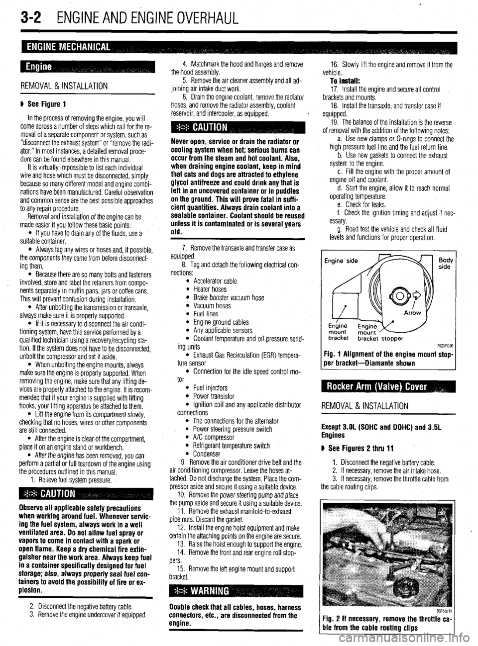
# See Figure 1
In the process of removing the engine, you will
come across a number of steps which call for the re-
moval of a separate component or system, such as
“disconnect the exhaust system” or “remove the radi-
ator.” In most instances, a detailed removal proce-
dure can be found elsewhere in this manual.
It is virtually impossible to list each individual
wire and hose which must be disconnected, simply
because so many different model and engrne combi-
nations have been manufactured Careful observation
and common sense are the best possible approaches
to any repair procedure.
Removal and installation of the engine can be
made easier if you follow these basic points:
l If you have to drain any of the fluids, use a
suitable container.
l Always tag any wires or hoses and, if possrble,
the components they came from before disconnect-
ing them.
l Because there are so many bolts and fasteners
involved, store and label the retainers from compo-
nents separately in muffin pans, jars or coffee cans.
This will prevent confusion during installatron.
l After unbolting the transmisston or transaxle,
always make sure it is properly supported.
l If it is necessary to disconnect the air condi-
tioning system, have this service performed by a
qualified technician using a recovery/recycling sta-
tion If the system does not have to be disconnected,
unbolt the compressor and set it aside.
l When unbolting the engine mounts, always
make sure the engine is properly supported. When
removing the engine, make sure that any lifting de-
vices are properly attached to the engine. It is recom-
mended that if your engine IS supplied with lifting
hooks, your lifting apparatus be attached to them.
l Lift the engine from its compartment slowly,
checking that no hoses, wires or other components
are still connected.
l After the engine is clear of the compartment,
place it on an engine stand or workbench.
l After the engine has been removed, you can
perform a partial or full teardown of the engine using
the procedures outlined in this manual.
1. Relieve fuel system pressure.
Observe all applicable safety precautions
when working around fuel. Whenever servic-
ing the fuel system, always work in a well
ventilated area. Do not allow fuel spray or
vapors to come in contact with a spark or
open flame. Keep a dry chemical fire extin-
guisher near the work area. Always keep fuel
in a container specifically designed for fuel
storage; also, always properly seal fuel con-
tainers to avoid the possibility of fire or ex-
plosion.
2. Disconnect the negative battery cable.
3. Remove the engine undercover if equipped. 4. Matchmark the hood and hinges and remove
the hood assembly.
5. Remove the air cleaner assembly and all ad-
joining air intake duct work.
6. Drain the engine coolant, remove the radiator
hoses, and remove the radiator assembly, coolant
reservoir, and intercooler, as equipped.
cooling system when hot; serious burns can
occur from the steam and hot coolant. Also,
when draining engine coolant, keep in mind
that cats and dogs are attracted to ethylene
glycol antifreeze and could drink any that is
left in an uncovered container or in puddles
on the ground. This will prove fatal in suffi-
cient quantities. Always drain coolant into a
sealable container. Coolant should be reused
unless it is contaminated or is several years
old.
7. Remove the transaxle and transfer case as
equipped.
8. Tag and detach the following electrical con-
nections:
l Accelerator cable l Heater hoses l Brake booster vacuum hose l Vacuum hoses l Fuel lines l Engine ground cables l Any applicable sensors l Coolant temperature and oil pressure send-
ing units
l Exhaust Gas Recirculation (EGR) tempera-
ture sensor
l Connection for the idle speed control mo-
tor
l Fuel injectors l Power transistor l Ignition coil and any applicable distributor
connections
l The connections for the alternator l Power steering pressure switch l A/C compressor l Refrigerant temperature switch l Condenser
9. Remove the air conditioner drive belt and the
air conditioning compressor. Leave the hoses at-
tached. Do not discharge the system. Place the com-
pressor aside and secure it using a suitable device.
10. Remove the power steering pump and place
the pump asrde and secure it using a surtable device.
11. Remove the exhaust manifold-to-exhaust
pipe nuts. Discard the gasket.
12. Install the engine hoist equipment and make
certain the attaching points on the engine are secure.
13. Raise the hoist enough to support the engine.
14. Remove the front and rear engine roll stop-
pers
15. Remove the left engine mount and support
Double check that all cables, hoses, harness
connectors, etc., are disconnected from the
engine.
16. Slowly lift the engine and remove it from the
vehicle.
To install:
17. Install the engine and secure all control
brackets and mounts.
18. Install the transaxle, and transfer case if
equipped.
19. The balance of the installation is the reverse
of removal with the addition of the following notes:
a. Use new clamps or O-rings to connect the
high pressure fuel lme and the fuel return line.
b. Use new gaskets to connect the exhaust
system to the engine.
c. Fill the engine with the proper amount of
engine oil and coolant.
d. Start the engine, allow it to reach normal
operating temperature.
e. Check for leaks.
f. Check the ignition timing and adjust if nec-
essary.
g. Road test the vehicle and check all fluid
levels and functions for proper operation.
Fig. 1 Alignment of the engine mount stop-
oer bracket-Diamante shown
REMOVAL &INSTALLATION
Except 3.OL (SOHC and DOHC) and 3.5L
Engines
# See Figures 2 thru 11
1. Disconnect the negative battery cable.
2. If necessary, remove the air intake hose.
3. If necessary, remove the throttle cable from
the cable routing clips.
Fig. 2 If necessary, remove the throttle ca-
ble from the cable routing clips
Page 79 of 408
l
3-18 ENGINEANDENGINEOVERHAUL
bolt and gaskets that connect the oil feed line to the
turbo center section and the water cooling lines. The
water line under the turbo has a threaded connection.
8. Remove the exhaust pipe nuts and gasket and
lift off the exhaust manifold. Discard the gasket,
9. Remove the 2 through bolts and 2 nuts that 16. If removed, install the power steering pump
and bracket.
17. Install the heat shields, air outlet hose, waste-
gate hose and air intake bellows.
18. Install the oil dipstick tube and dipstick. In-
stall the oxyqen sensor. cient quantities. Always drain coolant into a
sealable container. Coolant should be reused
unless it is contaminated or is several years
old.
3. Disconnect the overflow tube. Some vehicles
hold the exhaust manifold to the turbocharger,
10. Remove the 2 capscrews from the oil return
line (under the turbo). Discard the gasket. Separate
the turbo from the exhaust manifold. The 2 water
pipes and oil feed line can still be attached. 19. In&h the radiator assembly.
20. Fill the engine with oil, fill the cooling system
and reconnect the negative battery cable.
11. Visually check the turbine wheel (hot side)
and compressor wheel (cold side) for cracking or
other damage. Check whether the turbine wheel and
the compressor wheel can be easily turned by hand.
Check for oil leakaae. Check whether or not the Operating the engine without the proper
amount and type of engine oil will result in
severe engine damage.
wastegate valve remains open. If any problem is .
found, replace the part. Inspect oil passages for re- #I , I
striction or deposits and clean as required,
12. The wasteaate can be checked with a ores-
REMOVAL & INSTALLATION sure tester. Apply approximately 9 psi to the&h&or
and make sure the rod moves. Do not apply more
than 10.3 psi or the diaphragm in the wastegate may
be damaged. Vacuum applied to the wastegate actua-
tor should be maintained, replace if leaks vacuum,
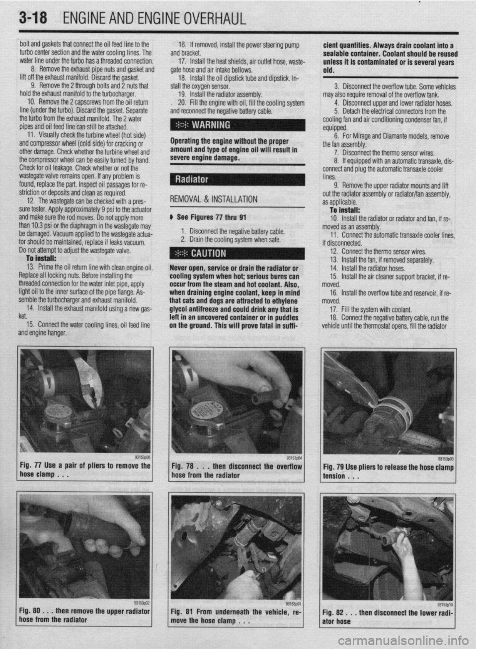
Do not attempt to adjust the wastegate valve. $ See Figures 77 thru 91
I. Disconnect the negative battery cable.
2. Drain the cooling system when safe.
To
install: 13. Prime the oil return line with clean engine oil.
Replace all locking nuts. Before installing the
threaded connection for the water inlet pipe, apply
light oil to the inner surface of the pipe flange. As-
semble the turbocharger and exhaust manifold.
14. Install the exhaust manifold using a new gas-
ket.
15. Connect the water cooling lines, oil feed line
and engine hanger. Never open, service or drain the radiator or
cooling system when hot: serious burns can
occur from the steam and hot coolant. Also,
when draining engine coolant, keep in mind
that cats and dogs are attracted to ethylene
glyeol antifreeze and could drink any that is
left in an uncovered container or in puddles
on the ground. This will prove fatal in suffi-
Fig. 77 Use a pair of pliers to remove the
Fig. 78 . . .
then disconnect the overflow
hose clamp . . .
hose from the radiator may also require removal of the overflow tank.
4. Disconnect upper and lower radiator hoses.
5. Detach the electrical connectors from the
cooling fan and air conditioning condenser fan, if
equipped.
6. For Mirage and Diamante models, remove
the fan assembly.
7. Disconnect the therm0 sensor wires,
8. If equipped with an automatic transaxle, dis-
connect and plug the automatic transaxle cooler
lines.
9. Remove the upper radiator mounts and lift
out the radiator assembly or radiator/fan assembly,
as applicable.
To install:
10. Install the radiator or radiator and fan, if re-
moved as an assembly.
11. Connect the automatic transaxle cooler lines
if disconnected.
12. Connect the therm0 sensor wires,
13. Install the fan, if removed separately.
14. Install the radiator hoses.
15. Install the air cleaner support bracket, if re-
noved.
16. Install the overflow tube and reservoir, if re-
noved.
17. Fill the system with coolant.
18. Connect the negative battery cable, run the
vehicle until the thermostat opens, fill the radiator
93153003 Fig. 79 Use pliers to release the hose clamp
tension . . .
Fig. 80 . . .
then remove the upper radiator
hose from the radiator Fig. 81 From underneath the vehicle, re-
move the hose clamp , . . ”
then disconnect the lower radi- Fig. 82 . . .
ator hose
Page 103 of 408
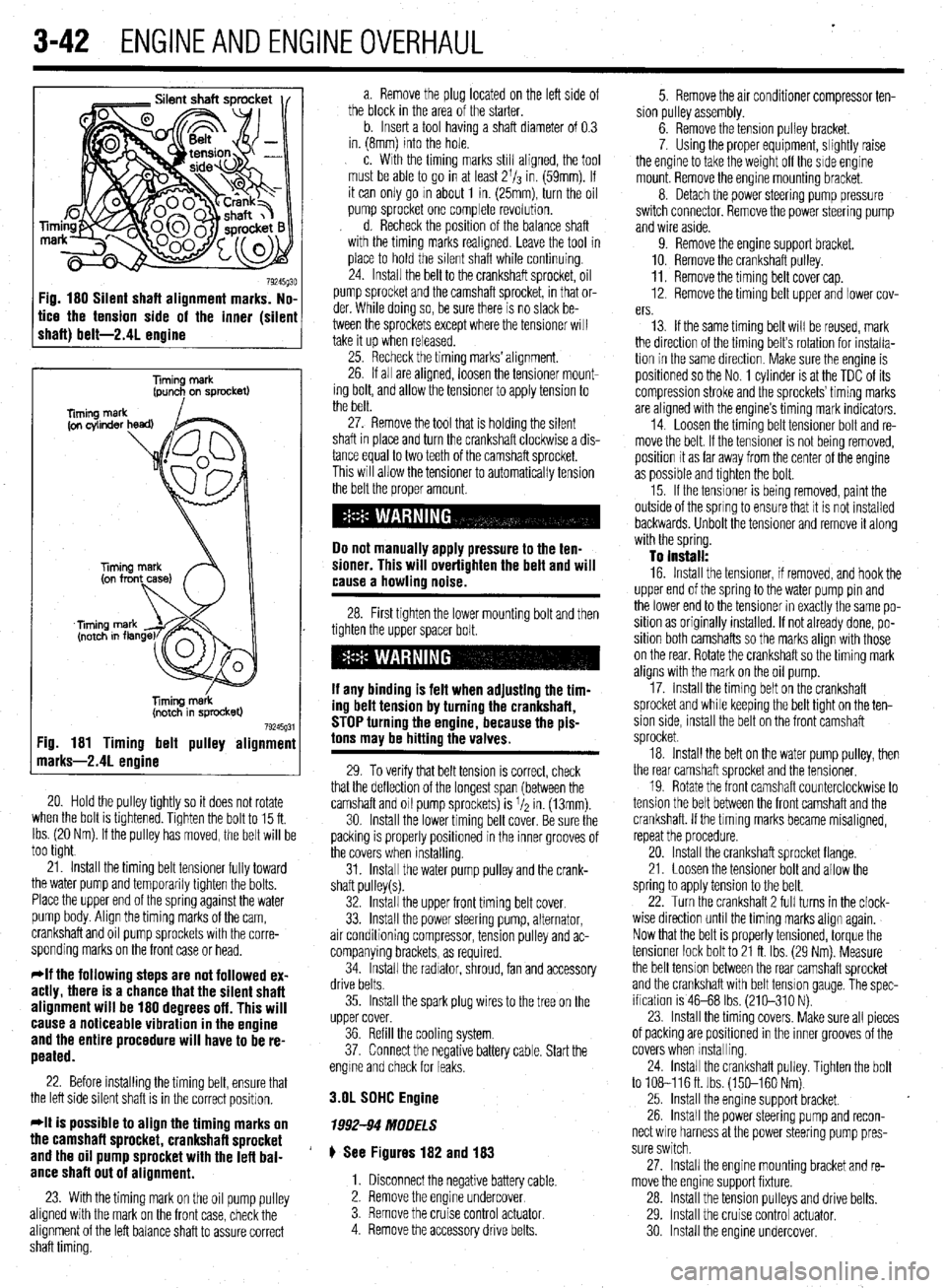
.
3-42 ENGINEANDENGINEOVERHAUL
Fig. 180 Silent shaft alignment marks. No,
tice the tension side of the inner (silen
shaft) belt-2.41 enaine
Timing merk
(pun+ on sprocket)
liming m&k
(notch in sprocket)
79245g31 :ig. 181 Timing belt pulley alignmenl
narks-2.41 enoine
20. Hold the pulley tightly so it does not rotate
when the bolt is tlghtened. Tighten the bolt to 15 ft.
Ibs. (20 Nm). If the pulley has moved, the belt will be
too tight
21. Install the timing belt tensioner fully toward
the water pump and temporarily tighten the bolts.
Place the upper end of the spring against the water
pump body. Align the timing marks of the cam,
crankshaft and oil pump sprockets with the corre-
sponding marks on the front case or head.
*If the following steps are not followed ex-
actly, there is a chance that the silent shaft
alignment will be 180 degrees off. This will
cause a noticeable vibration in the engine
and the entire procedure will have to be re-
peated.
22. Before installing the timing belt, ensure that
the left side silent shaft is in the correct position.
*It is possible to align the timing marks on
the camshaft sprocket, crankshaft sprocket
and the oil pump sprocket with the lefl bal-
ance shaft out of alignment.
23. With the timing mark on the oil pump pulley
aligned with the mark on the front case, check the
alignment of the left balance shaft to assure correct
shaft timing. a. Remove the plug located on the left side of
the block in the area of the starter.
b. Insert a tool having a shaft diameter of 0.3
in. (8mm) into the hole.
c. With the timing marks still aligned, the tool
must be able to go in at least 2l/s in. (59mm). If
it can only go m about 1 in. (25mm), turn the oil
pump sprocket one complete revolution.
d. Recheck the position of the balance shaft
with the timing marks reahgned. Leave the tool in
place to hold the silent shaft while continuing.
24. Install the belt to the crankshaft sprocket, oil
pump sprocket and the camshaft sprocket, in that or-
der. While doing so, be sure there is no slack be-
tween the sprockets except where the tensioner will
take it up when released.
25. Recheck the timing marks’ alignment.
26. If all are aligned, loosen the tensioner mount-
ing bolt, and allow the tensioner to apply tension to
the belt.
27. Remove the tool that is holding the silent
shaft in place and turn the crankshaft clockwise a dis-
tance equal to two teeth of the camshaft sprocket.
This will allow the tensioner to automatically tension
the belt the proper amount.
Do not manually apply pressure to the ten-
sioner. This will overtighten the belt and will
cause a howling noise.
28. First tighten the lower mounting bolt and then
tighten the upper spacer bolt.
If any binding is felt when adiustino the tim-
ing delt tension by turning th;! crankshaft,
STOP turning the engine, because the pis-
tons may be hitting the valves.
29. To verify that belt tension is correct, check
that the deflection of the longest span (between the
camshaft and oil pump sprockets) is I/* in. (13mm).
30. Install the lower timing belt cover. Be sure the
packing is properly positioned in the inner grooves of
the covers when installing.
31. Install the water pump pulley and the crank-
shaft pulley(s).
32. Install the upper front timing belt cover.
33. Install the power steering pump, alternator,
air conditioning compressor, tension pulley and ac-
companying brackets, as required.
34. Install the radiator, shroud, fan and accessory
drive belts.
35. Install the spark plug wires to the tree on the
upper cover.
36. Refill the cooling system.
37. Connect the negative battery cable. Start the
engme and check for leaks.
3.OL SDHC Engine
1992-94 MODELS
# See Figures 182 and 183
1. Disconnect the negative battery cable.
2. Remove the engine undercover
3. Remove the cruise control
actuator 4. Remove the accessory drive belts. 5. Remove the air conditioner compressor ten-
sion pulley assembly.
6. Remove the tension pulley bracket.
7. Using the proper equipment, slightly raise
the engine to take the weight off the side engine
mount. Remove the engine mounting bracket.
8. Detach the power steering pump pressure
switch connector. Remove the power steering pump
and wire aside.
9. Remove the engine support bracket.
10. Remove the crankshaft pulley.
11. Remove the timing belt cover cap.
12. Remove the timing belt upper and lower cov-
ers.
13. If the same timing belt will be reused, mark
the direction of the timing belt’s rotation for installa-
tion in the same direction. Make sure the engine is
positioned so the No. 1 cylinder is at the TDC of its
compression stroke and the sprockets’ timing marks
are aligned with the engine’s timing mark indicators.
14. Loosen the timing belt tensioner bolt and re-
move the belt. If the tensioner is not being removed,
position it as far away from the center of the engine
as possible and tighten the bolt.
15. If the tensioner is being removed, paint the
outside of the spring to ensure that it is not installed
backwards. Unbolt the tensioner and remove it along
with the spring.
To install:
16. Install the tensioner, if removed, and hook the
upper end of the spring to the water pump pin and
the lower end to the tensioner in exactly the same po-
sition as originally installed. If not already done, po-
sition both camshafts so the marks align with those
on the rear. Rotate the crankshaft so the timing mark
aligns with the mark on the oil pump.
17. Install the timing belt on the crankshaft
sprocket and while keeping the belt tight on the ten-
sion side, install the belt on the front camshaft
sprocket.
18. Install the belt on the water pump pulley, then
the rear camshaft sprocket and the tensioner.
19. Rotate the front camshaft counterclockwise to
tension the belt between the front camshaft and the
crankshaft. If the tlmlng marks became misaligned,
repeat the procedure.
20. Install the crankshaft sprocket flange.
21. Loosen the tensioner bolt and allow the
spring to apply tension to the belt.
22. Turn the crankshaft 2 full turns in the clock-
wise direction until the timing marks align again.
Now that the belt is properly tensioned, torque the
tensioner lock bolt to 21 ft. Ibs. (29 Nm). Measure
the belt tension between the rear camshaft sprocket
and the crankshaft with belt tension gauge, The spec-
ification is 46-68 Ibs. (210-310 N).
23. Install the timing covers. Make sure all pieces
of packing are positioned in the inner grooves of the
covers when Installing.
24. install the crankshaft pulley. Tighten the bolt
to 108-116ft. Ibs. (150-160 Nm)
25. Install the engine support bracket.
26. Install the power steering pump and recon-
nect wire harness at the power steering pump pres-
sure switch.
27. Install the engine mounting bracket and re-
move the engine support fixture.
28. Install the tension pulleys and drive belts.
29. Install the cruise control actuator.
30 Install the engine undercover.
Page 105 of 408
.
3-44 ENGINEANDENGINEOVERHALJL
31. Connect the negative battery cable.
32. Road test the vehicle.
EXCEPT 1992-94 MODELS
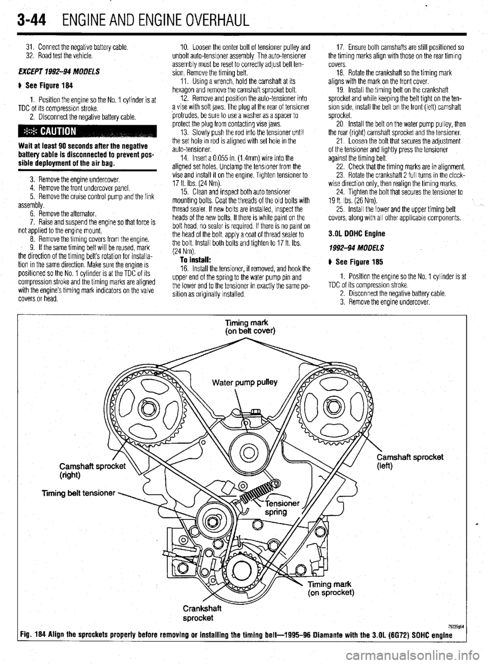
$ See Figure 184
1. Position the engine so the No. 1 cylinder is at
TDC of its compression stroke.
2. Disconnect the negative battery cable.
Wait at least 90 seconds after the negative
battery cable is disconnected to prevent pos-
sible deployment of the air bag.
3. Remove the engine undercover.
4. Remove the front undercover panel.
5. Remove the cruise control pump and the link
assembly.
6. Remove the alternator.
7. Raise and suspend the engine so that force is
not applied to the engme mount,
8. Remove the timing covers from the engine.
9. If the same timing belt will be reused, mark
the direction of the timing belt’s rotation for installa-
tion in the same direction. Make sure the engine is
positroned so the No. 1 cylinder is at the TDC of its
compression stroke and the timing marks are aligned
with the engine’s timing mark indicators on the valve
covers or head. 10. Loosen the center bolt of tensioner pulley and
unbolt auto-tensioner assembly The auto-tensioner
assembly must be reset to correctly adjust belt ten-
sion. Remove the timing belt.
11. Using a wrench, hold the camshaft at its
hexagon and remove the camshaft sprocket bolt.
12. Remove and position the auto-tensioner into
a vise with soft jaws. The plug at the rear of tensioner
protrudes, be sure to use a washer as a spacer to
protect the plug from contacting vise jaws.
13. Slowly push the rod Into the tensioner until
the set hole rn rod is aligned with set hole in the
auto-tensioner.
14. Insert a 0.055 in. (1.4mm) wire into the
aligned set holes. Unclamp the tensioner from the
vise and install it on the engine. Trghten tensroner to
17 ft. Ibs. (24 Nm).
15. Clean and inspect both auto tensioner
mounting bolts. Coat the threads of the old bolts with
thread sealer. If new bolts are installed, Inspect the
heads of the new bolts. If there is white paint on the
bolt head, no sealer is required. If there is no parnt on
the head of the bolt, apply a coat of thread sealer to
the bolt. Install both bolts and tighten to 17 ft. Ibs.
(24 Nm).
To install: 16. Install the tensioner, if removed, and hook the
upper end of the spring to the water pump pin and
the lower end to the tensioner in exactly the same po-
sition as originally installed. 17. Ensure both camshafts are still positioned so
the timing marks align with those on the rear timing
covers.
18. Rotate the crankshaft so the timing mark
aligns with the mark on the front cover.
19. Install the timing belt on the crankshaft
sprocket and while keeping the belt tight on the ten-
sion side, mstall the belt on the front (left) camshaft
sprocket.
20 Install the belt on the water pump pulley, then
the rear (right) camshaft sprocket and the tensioner.
21. Loosen the bolt that secures the adjustment
of the tensioner and lightly press the tensioner
against the timing belt.
22. Check that the timing marks are in alignment.
23 Rotate the crankshaft 2 full turns in the clock-
wise direction only, then realign the timing marks,
24. Tighten the bolt that secures the tensioner to
19 ft. Ibs. (26 Nm).
25. install the lower and the upper timing belt
covers, along with all other applicable components.
3.OL DDHC Engine
1992-94 MODELS
# See Figure 185
1. Position the engine so the No. 1 cylinder is at
TDC of its compression stroke.
2. Disconnect the negative battery cable.
3. Remove the engine undercover.
Timing mark
(on belt cover)
Timing belt tensioner
Crankshaft
sprocket
7923W :ig. 184 Align the sprockets properly before removing or installing the timing belt-1995-96 Diamante with the 3.OL (6672) SDHC engine
Page 107 of 408
3-46 ENGINEANDENGINEOVERHAUL
29. Install the engine support bracket and secure
using mounting bolts in their original location. Lubri-
cate the reaming area of the reamer bolt and tighten
slowly.
30. Install the idler pulley.
31. Install the engine mount bracket. Remove the
engine support fixture.
32. Make sure all pieces of packing are posi-
tioned in the inner grooves of the upper cover and in-
stall.
33. Connect the brake fluid level sensor.
34. Install the crankshaft pulley. Tighten the bolt
to 130-137ft. Ibs. (180-190 Nm).
35. install the belt tensioner assembly and the
power steering belt.
36 install the air hose and pipe.
37 Install the alternator.
38. Install the cruise control actuator.
39. Install the engine undercover.
40. Connect the negative battery cable.
199546 MODELS
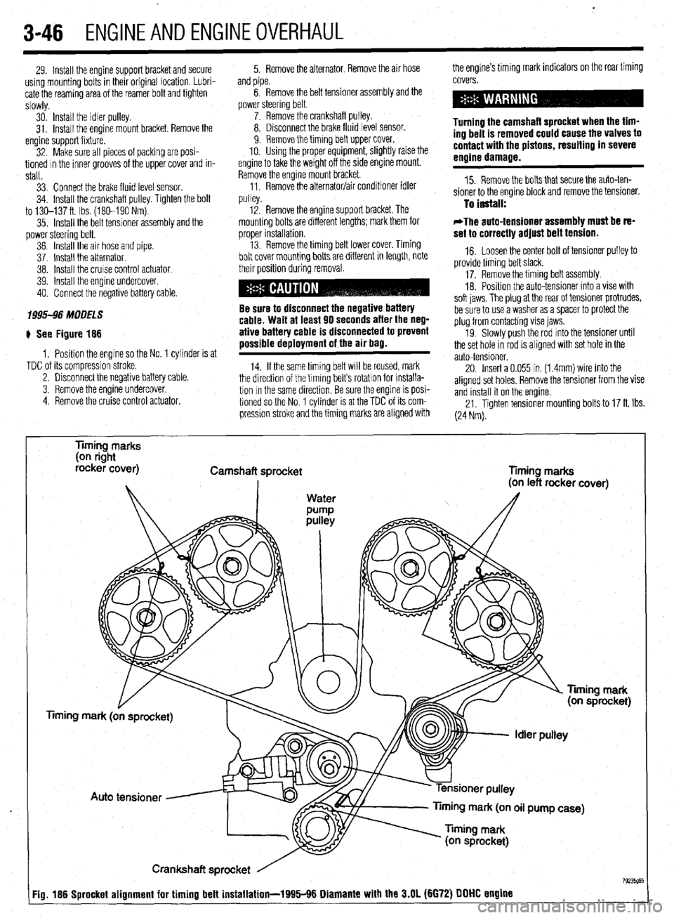
# See Figure 186
1, Position the engine so the No. 1 cylinder is at
TDC of its compression stroke.
2. Disconnect the negative battery cable.
3. Remove the engine undercover.
4 Remove the cruise control actuator. 5. Remove the alternator, Remove the air hose the engine’s timing mark indicators on the rear timing
and pipe.
6. Remove the belt tensioner assembly and the
power steering belt.
7. Remove the crankshaft pulley.
8. Disconnect the brake fluid level sensor.
9. Remove the timing belt upper cover.
10. Using the proper equipment, slightly raise the
engine to take the weight off the side engine mount.
Remove the engine mount bracket.
11, Remove the alternator/air conditioner idler
..,,ll^,. covers.
Turning the camshaft sprocket when the tim-
ing belt is removed could cause the valves to
contact with the pistons, resulting in severe
engine damage.
15. Remove the bolts that secure the auto-ten-
sioner to the engine block and remove the tensioner.
pu,ey. 12. Remove the engine support bracket. The To install:
mounting bolts are different lengths; mark them for
orooer installation. *The auto-tensioner assembly must be re-
set to correctlv adiust belt tension. , . 13. Remove the timing belt lower cover. Timing
bolt cover mounting bolts are different in length, note
their position during removal.
Be sure to disconnect the negative battery
cable. Wait at least 90 seconds after the neg-
ative battery cable is disconnected to prevent
possible deployment of the air bag.
14. If the same timing belt WIII be reused, mark
the direction of the trming belts rotation for installa-
tion In the same direction, Be sure the engine is posi-
tioned so the No. 1 cylinder is at the TDC of its com-
pression stroke and the timing marks are aligned with _ -
16. Loosen the center bolt of tensioner pulley to
provide timing belt slack.
17. Remove the timing belt assembly.
18. Posrtion the auto-tensioner into a vise with
soft iaws. The olua at the rear of tensioner protrudes,
be sure to usea v&her as a spacer to protect the
plug from contacting vise jaws.
19. Slowly push the rod mto the tensioner until
the set hole in rod is aligned with set hole in the
auto-tensioner.
20. Insert a 0.055 in. (1.4mm) wire into the
aligned set holes, Remove the tensioner from the vise
and install it on the engine.
21. Tighten tensioner mounting bolts to 17 ft. Ibs.
(24 Nm).
Timing marks
(on right
rocker cover)
Camshaft sprocket
Timing marks
mark (on oil pump case)
Crankshaft sprocket
Fig. 186 Sprocket alignment for timing belt installation-1995116 Diamante with the 3.N (6672) DDDD engine
Page 116 of 408
ENGINEANDENGINEOVERHAUL 3-55
8. Run a bead of sealer along any seams be-
tween the seal case and block. Install the seal case
with a new gasket.
9. Install the flywheel/driveplate and transaxle.
10. Connect the negative battery cable and check
for leaks.
11. Adjust oil level as necessary.
REMOVAL &INSTALLATION To lnstell:
7. Coat the threads of the driveplate/flywheel re-
taining bolts with thread locking compound.
8. Position the driveplatelflywheel on the crank-
shaft flange.
9. On automatic transaxle equipped models, in-
stall the driveplate adapter.
10. Install and tighten the bolts, in a alternating
star pattern, to the following specifications:
l 1.5L engine: 98 ft. Ibs. (135 Nm) l 1.6L, 2.01 and 2.4L engines: 94-101 ft.
Ibs. (130-140 Nm)
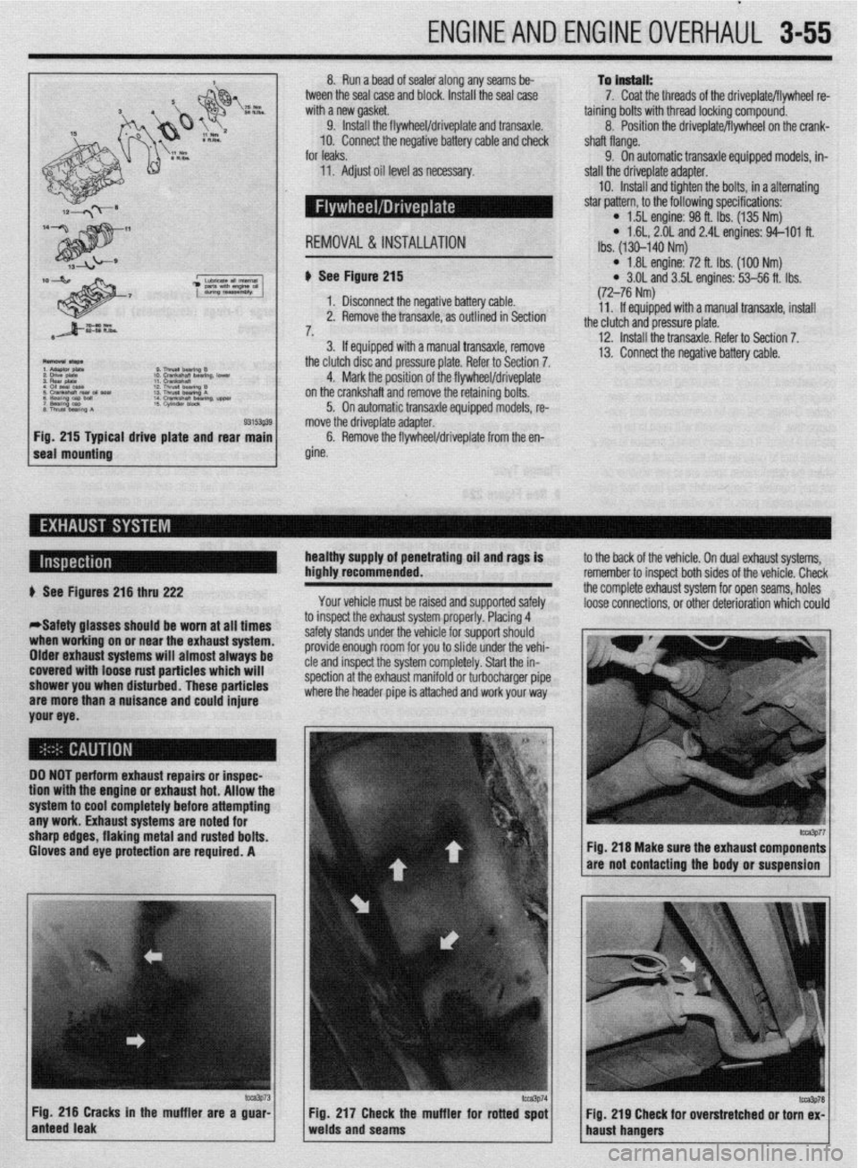
al drive plate and rear b See Figure 215
1. Disconnect the negative battery cable.
2. Remove the transaxle, as outlined in Section
7,
3. If equipped with a manual transaxle, remove
the clutch disc and pressure plate. Refer to Section 7.
4. Mark the position of the flywheel/driveplate
on the crankshaft and remove the retaining bolts.
5. On automatic transaxle equipped models, re-
move the driveplate adapter.
6. Remove the flywheel/driveplate from the en-
gine.
l 1.81 engine: 72 ft. Ibs. (100 Nm) l 3.OL and 3.5L engines: 53-56 ft. Ibs.
(72-76 Nm)
11. If equipped with a manual transaxle, install
the clutch and pressure plate.
12. Install the transaxle. Refer to Section 7.
13. Connect the negative battery cable.
healthy supply of penetrating oil and rags is
highly recommended.
Your vehicle must be raised and supported safely to the back of the vehicle. On dual exhaust systems,
remember to insoect both sides of the vehicle. Check
the complete exhaust system for open seams, holes
loose connections, or other deterioration which could + See Figures 216 thru 222
*Safety glasses should be worn at all times
when working on or near the exhaust system.
Older exhaust systems will almost always be
covered with loose rust particles which will
shower you when disturbed. These particles
are more than a nuisance and could injure
your eye. to inspect the exhaust system properly. Placing 4
safety stands under the vehicle for support should
provide enough room for you to slide under the vehi-
cle and inspect the system completely. Start the in-
spection at the exhaust manifold or turbocharger pipe
where the header pipe is attached and work your way
DO NOT perform exhaust repairs or inspec-
tion wtth the engine or exhaust hot. Allow thr
system to cool completely before attempting
any work. Exhaust systems are noted for
sharp edges, flaking metal and rusted bolts.
Gloves and eye protection are required. A
m3p73 Fig. 216 Cracks in the muffler are a guar-
anteed leak Fig 217 Check the muffler for rotted spot
Fig. 219 Cheek for overstretched or torn ex-
welds and seams
haust hangers
fm3p77 Fig. 216 Make sure the exhaust components
are not contacting the body or suspension
lcca3P78
Page 117 of 408
3-56 ENGINEANDENGINEOVERHAUL
,
F C
F
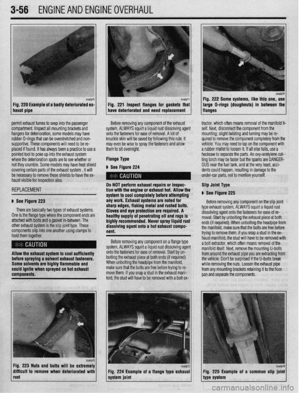
t
. Fig.
220 Example of a badly deteriorated ex- 1 Fig. 221 inspect flanges for gaskets that
haust pipe have deteriorated and need replacement Fig. 222 Some systems, like this one, use
)ermit exhaust fumes to seep into the passenger
:ompartment. Inspect all mounting brackets and
bangers for deterioration, some models may have
ubber O-rings that can be overstretched and non-
supportive. These components will need to be re-
Ilaced if found. It has always been a practice to use a
)ointed tool to poke up into the exhaist system
vhere the deterioration spots are to see whether or
d they crumble. Some models may have heat shield
:overing certain parts of the exhaust system , it will
te necessary to remove these shields to have the ex-
laust visible for inspection also. Before removing any component of the exhaust
system, ALWAYS squirt a Liquid rust dissolving agent
onto the fasteners for ease of removal. A lot of
knuckle skin will be saved by following this rule. It
may even be wise to spray the fasteners and allow
them to sit overniqht.
Flange Type
b See Figure 224 tractor, which oflen means removal of the manifold it
self. Next, disconnect the component from the
mounting; slight twisting and turning may be re-
quired to remove the component completely from thr
vehicle. You may need to tap on the component with
a rubber mallet to loosen it. If all else fails, use a
hacksaw to sep; arate the parts. An oxy-acetylene cut-
ting torch may I 3e faster but the sparks are OANGER-
OUS near the fuel tank, ant 1 at the very least, acci-
dents could happen, result ing in damage to the
under-car parts, not to mei ition yourself.
3EPLACEMEMT
1 See Figure 223
There are basically two types of exhaust systems.
)ne is the flange type where the component ends are
attached with bolts and a gasket in-between. The
)ther exhaust system is the slip joint type. These
:omponents slip into one another using clamps to
iold them together. Do NOT perform exhaust repairs or inspec-
tion with the engine or exhaust hot. Allow the
system to cool completely before attempting
any work. Exhaust systems are noted for
sharp edges, flaking metal and rusted bolts.
Gloves and eye protection are required. A
healthy supply of penetrating oil and
rags is
highly recommended. Never spray liquid rust
dissolving agent onto a hot exhaust compo-
nent. Slip Joint Type
V See Figure 225
Before removing any component on the slip joint
type exhaust system, ALWAYS squirt a liquid rust
dissolving agent onto the fasteners for ease of re-
moval. Start by unbolting the exhaust piece at both
ends (if required). When unbolting the headpipe fron
the manifold, make sure that the bolts are free before
trying to remove them. if you snap a stud in the ex-
haust manifold. the stud will have to be removed wit1
Before removing any component on a flange type
system, ALWAYS squirt a liquid rust dissolving agent a bolt extractor, which often means removal of the
._ manifold itself. Next. remove the mountina U-bolts
liiow the exhaust system to cool sufficiently
Iefore spraying a solvent exhaust fasteners.
Some solvents are highly flammable and
:ould ignite when sprayed on hot exhauti
:omponents. onto the fasteners for ease of removal. Start by un-
bolting the exhaust piece at both ends (if required).
When unbolting the headpipe from the manifold,
make sure that the bolts are free before trying to re-
move them. if you snap a stud in the exhaust mani-
fold, the stud will have to be removed with a bolt ex-
ka3p70 Fig. 223 Nuts and bolts will be extremely
difflcuit to remove when deteriorated with
rust Fig. 224 Example of a flange type exhaust
system joint from around the exhaust pipe you are ext&ting from
the vehicle. Don’t be surprised if the U-bolts break
while removing the nuts. Loosen the exhaust pipe
from any mounting brackets retaining it to the floor
pan and separate the components.
Fig. 225 Example of a common slip joini
type system
Page 118 of 408
ENGINEANDENGINEOVERHAUL 3-57
Anything that generates heat and/or friction WIII
eventually burn or wear out (for example, a light bulb
generates heat, therefore its life span is limited). With
this in mind, a running engine generates tremendous
amounts of both; friction is encountered by the mov-
ing and rotating parts inside the engine and heat is
created by friction and combustion of the fuel How-
ever, the engine has systems designed to help reduce
the effects of heat and friction and provide added
longevrty. The oiling system reduces the amount of
friction encountered by the moving parts inside the
engine, while the cooling system reduces heat cre-
ated by friction and combustion If either system is
not maintained, a break-down will be inevitable.
Therefore, you can see how regular maintenance can
affect the service life of your vehicle, If you do not
drain, flush and refill your cooling system at the
proper intervals, deposits WIII begin to accumulate in
the radiator, thereby reducing the amount of heat it
can extract from the coolant The same applies to
your oil and filter; If it is not changed often enough it
becomes laden with contaminates and is unable to
properly lubricate the engine. This increases friction
and wear.
There are a number of methods for evaluating the
condition of your engine. A compression test can re-
veal the condition of your pistons, piston rings,
cylinder bores, head gasket(s), valves and valve
seats. An oil pressure test can warn you of possible
engine bearing, or oil pump failures. Excessrve oil
consumption, evidence of oil in the engine air intake
area and/or bluish smoke from the tailpipe may indi-
cate worn piston rings, worn valve guides and/or
valve seals. As a general rule, an engine that uses no
more than one quart of oil every 1000 miles is in
good condition. Engines that use one quart of oil or
more in less than 1000 miles should first be checked
for oil leaks. If any oil leaks are present, have them
fixed before determining how much oil is consumed
by the engine, especrally if blue smoke is not visible
at the tailpipe
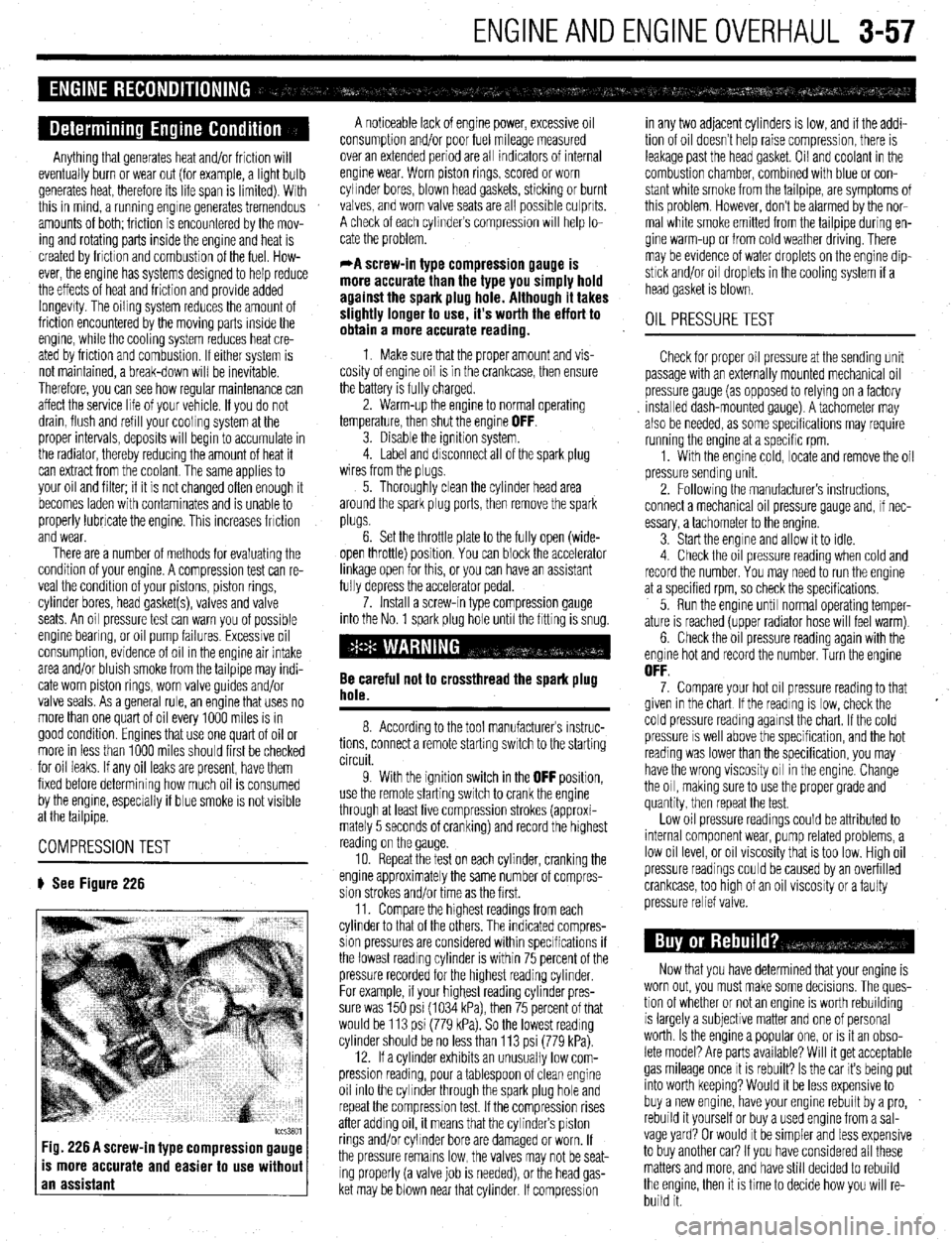
COMPRESSION TEST
# See Figure 226
tccs3801 Fig. 226 A screw-in type compression gauge
is more accurate and easier to use without
an assistant
A noticeable lack of engine power, excessive oil
consumption and/or poor fuel mileage measured
over an extended period are all indicators of internal
engine wear. Worn piston rings, scored or worn
cylinder bores, blown head gaskets, sticking or burnt
valves, and worn valve seats are all possible culprits.
A check of each cylinders compression WIII help lo-
cate the problem.
*A screw-in type compression gauge is
more accurate than the type you simply hold
against the spark plug hole. Although it takes
slightly longer to use, it’s worth the effort to
obtain a more accurate reading.
1 Make sure that the proper amount and vis-
cosity of engine oil is in the crankcase, then ensure
the battery is fully charged.
2. Warm-up the engine to normal operating
temperature, then shut the engine
OFF. 3. Disable the ignition system.
4. Label and disconnect all of the spark plug
wires from the plugs,
5. Thoroughly clean the cylinder head area
around the spark plug ports, then remove the spark
plugs.
6. Set the throttle plate to the fully open (wide-
open throttle) position You can block the accelerator
linkage open for this, or you can have an assistant
fully depress the accelerator pedal.
7. Install a screw-in type compression gauge
into the No. 1 spark plug hole until the fitting is snug.
Be careful not to crossthread the spark plug
hole.
8. According to the tool manufacturers instruc-
tions, connect a remote starting switch to the starting
circuit.
9. With the ignition switch in the
OFF position,
use the remote starting switch to crank the engine
through at least five compression strokes (approxi-
mately 5 seconds of cranking) and record the highest
reading on the gauge
10. Repeat the test on each cylinder, cranking the
engine approximately the same number of compres-
sion strokes and/or time as the first.
11. Compare the hrghest readings from each
cylinder to that of the others. The indicated compres-
sion pressures are considered within specifications if
the lowest reading cylinder is within 75 percent of the
pressure recorded for the highest reading cylinder
For example, if your highest reading cylinder pres-
sure was 150 psi (1034 kPa), then 75 percent of that
would be 113 psi (779 kPa). So the lowest reading
cylinder should be no less than 113 psi (779 kPa).
12. If a cylinder exhibits an unusually low com-
pression reading, pour a tablespoon of clean engine
oil into the cylinder through the spark plug hole and
repeat the compression test. If the compression rises
after adding oil, it means that the cylinder’s piston
rings and/or cylinder bore are damaged or worn, If
the pressure remains low, the valves may not be seat-
ing properly (a valve job is needed), or the head gas-
ket may be blown near that cylinder. If compression in any two adjacent cylinders is low, and if the addi-
tion of oil doesn’t help raise compression, there is
leakage past the head gasket. Oil and coolant in the
combustion chamber, combined with blue or con-
stant white smoke from the tailpipe, are symptoms of
this problem. However, don’t be alarmed by the nor-
mal white smoke emitted from the tailpipe during en-
gine warm-up or from cold weather driving. There
may be evidence of water droplets on the engine dip-
stick and/or oil droplets in the cooling system if a
head gasket is blown.
OIL PRESSURETEST
Check for proper oil pressure at the sending unit
passage with an externally mounted mechanical oil
pressure gauge (as opposed to relying on a factory
Installed dash-mounted gauge). A tachometer may
also be needed, as some specifications may require
running the engine at a specific rpm.
1. With the engine cold, locate and remove the oil
pressure sending unit.
2. Followrng the manufacturers instructions,
connect a mechanical oil pressure gauge and, if nec-
essary, a tachometer to the engine.
3 Start the engine and allow it to idle.
4 Check the oil pressure reading when cold and
record the number. You may need to run the engine
at a specified rpm, so check the specifications,
5. Run the engine until normal operating temper-
ature is reached (upper radiator hose will feel warm)
6. Check the oil pressure reading again with the
engine hot and record the number. Turn the engine
OFF. 7. Compare your hot oil pressure reading to that
given in the chart If the reading is low, check the
cold pressure reading against the chart. If the cold
pressure IS well above the specification, and the hot
reading was lower than the specification, you may
have the wrong viscosity oil in the engine. Change
the oil, making sure to use the proper grade and
quantity, then repeat the test.
Low oil pressure readings could be attributed to
internal component wear, pump related problems, a
low oil level, or oil viscosity that is too low. High oil
pressure readings could be caused by an overfilled
crankcase, too htgh of an oil viscosity or a faulty
pressure relief valve.
Now that you have determined that your engine is
worn out, you must make some decisions. The ques-
tion of whether or not an engine IS worth rebuilding
is largely a subjective matter and one of personal
worth. Is the engine a popular one, or IS it an obso-
lete model? Are parts available? Will it get acceptable
gas mileage once It is rebuilt? Is the car its being put
into worth keeping? Would it be less expensive to
buy a new engine, have your engine rebuilt by a pro,
rebuild it yourself or buy a used engine from a sal-
vage yard? Or would It be simpler and less expensive
to buy another car? If you have considered all these
matters and more, and have still decided to rebuild
the engine, then it is time to decide how you will re-
build it.