manual radio set MITSUBISHI DIAMANTE 1900 Repair Manual
[x] Cancel search | Manufacturer: MITSUBISHI, Model Year: 1900, Model line: DIAMANTE, Model: MITSUBISHI DIAMANTE 1900Pages: 408, PDF Size: 71.03 MB
Page 372 of 408

10-4 BODYANDTRIM
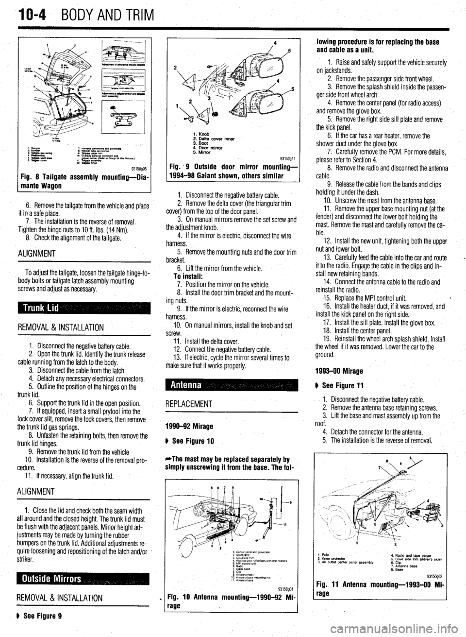
Fig. 8 Tailgate assembly mounting-Dia-
mante Wagon
6. Remove the tailgate from the vehicle and place
it in a safe place.
7. The installation is the reverse of removal.
Tighten the hinge
nuts to IO ft. Ibs. (14 Nm).
8. Check the alignment of the tailgate.
ALIGNMENT
To adjust the tailgate, loosen the tailgate hinge-to-
body bolts or tailgate latch assembly mounting
screws and adjust as necessary.
REMOVAL &INSTALLATION
1. Disconnect the negative battery cable.
2. Open the trunk lid. Identify the trunk release
cable running from the latch to the body.
3. Disconnect the cable from the latch.
4. Detach any necessary electrical connectors.
5. Outline the position of the hinges on the
trunk lid.
6. Support the trunk lid in the open position.
7. If equipped, insert a small prytool into the
lock cover slit, remove the lock covers, then remove
the trunk lid gas springs.
8. Unfasten the retaining bolts, then remove the
trunk lid hinges.
9. Remove the trunk lid from the vehicle
10. Installation is the reverse of the removal pro-
cedure.
11. If necessary, align the trunk lid.
ALIGNMENT
1. Close the lid and check both the seam width
all around and the closed height. The trunk lid must
be flush with the adjacent panels. Minor height ad-
justments may be made by turning the rubber
bumpers on the trunk lid. Additional adjustments re-
quire loosening and repositioning of the latch and/or
striker.
REMOVAL &INSTALLATION
? See Figure 9
1. Knob 2. Delta cover inner
3. Boot
4. Door mirror
5. Mirror
Fig. .9 Outside door mirror
1994-98 Galant shown
, others 9315oQ1 i mounting-
similar
1. Disconnect the negative battery cable.
2. Remove the delta cover (the triangular trim
cover) from the top of the door panel.
3. On manual mirrors remove the set screw and
the adjustment knob.
4. If the mirror is electric, disconnect the wire
harness.
5. Remove the mounting nuts and the door trim
bracket.
6. Lift the mirror from the vehicle.
To install: 7. Position the mirror on the vehicle.
8. Install the door trim bracket and the mount-
ing nuts.
9. If the mirror is electric, reconnect the wire
harness.
IO. On manual mirrors, install the knob and set
screw.
11. Install the delta cover.
12. Connect the negative battery cable.
13. If electric, cycle the mirror several times to
make sure that it works properly.
# See Figure 11
REPLACEMENT
1990-92 Mirage
b
See Figure 10
*The mast may be replaced separately by
simply unscrewing it from the base. The fol-
1. center panel and glove box
2 scuff plate
3 cowl 51ae wm
4 Washer duct
7 CaMeband
8 cap
9 Anrsnna mast
10 Antenna base “ourmng ““f
11 Antennz.base
%i%Qol
Fig. 10 Antenna mounting-1990-92 Mi-
rage lowing procedure is for replacing the base
and cable as a unit.
1 I Raise and safely support the vehicle securely
on jackstands.
2. Remove the passenger side front wheel.
3. Remove the splash shield inside the passen-
ger side front wheel arch.
4. Remove the center panel {for radio access)
and remove the glove box.
5. Remove the right side sill plate and remove
the kick panel.
6. If the car has a rear heater, remove the
shower duct under the glove box.
7. Carefully remove the PCM. For more details,
please refer to Section 4.
8. Remove the radio and disconnect the antenna
cable.
9. Release the cable from the bands and clips
holding it under the dash.
10. Unscrew the mast from the antenna base.
II. Remove the upper base mounting nut (at the
fender) and disconnect the lower bolt holding the
mast. Remove the mast and carefully remove the ca-
ble.
12. Install the new unit, tightening both the upper
nut and lower bolt.
13. Carefully feed the cable into the car and route
it to the radio. Engage the cable in the clips and in-
stall new retaining bands.
14. Connect the antenna cable to the radio and
reinstall the radio.
15. Replace the MPI control unit. t
16. Install the heater duct, if it was removed, and
install the kick panel on the right side.
17. Install the sill plate. Install the glove box.
18. Install the center panel.
19. Reinstall the wheel arch splash shield. Install
the wheel if it was removed. Lower the car to the
ground.
1993-00 Mirage
I. Disconnect the negative battery cable.
2. Remove the antenna base retaining screws.
3. Lift the base and mast assembly up from the
roof.
4. Detach the connector for the antenna.
5. The installation is the reverse of removal.
1. Pole
2. Knee protactor
3. Air outlet center panel assembly 4. Radto and laps player
5. Cowl side trim (driver’s side)
6. Chp
7. Antenna base
6. Base
931 !iogo2 Fig. 11 Antenna mounting-1993-00 Mi-
rage