radio MITSUBISHI DIAMANTE 1900 Repair Manual
[x] Cancel search | Manufacturer: MITSUBISHI, Model Year: 1900, Model line: DIAMANTE, Model: MITSUBISHI DIAMANTE 1900Pages: 408, PDF Size: 71.03 MB
Page 42 of 408
GENERALINFORMATIONAND MAINTENANCE l-43
l Special car washing detergent is the best to
use. Liquid dishwashing detergent can remove wax
and leave the car’s paint unprotected and in addition
some liquid detergents contains abrasives which can
scratch the paint.
l Bird droppings should be removed from the
paintwork as soon as possible, otherwise the finish
may be permanently stained.
When the car is driven immediately after be-
ing washed, apply the brakes several times
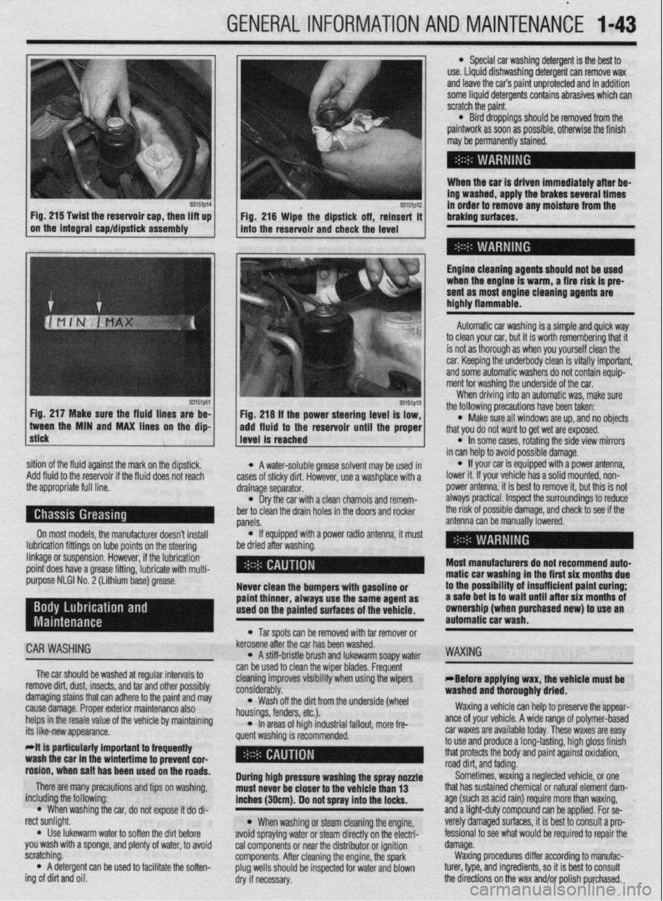
93151p14 93151p12 Fig. 215 Twist the reservoir cap, then lift up
I I
in order to remove any moisture from the
Fig. 216 Wipe the dipstick off, reinsert it braking surfaces.
on the integral cap/dipstick assembly
into the reservoir and check the level
I
Engine cleaning agents should not be used
when the engine is warm, a fire risk is pre-
sent as most engine cleaning agents are
highly flammable.
sition of the fluid against the mark on the dipstick,
Add fluid to the reservoir if the fluid does not reach
the appropriate full line.
On most models, the manufacturer doesn’t install
lubrication fittings on lube points on the steering
linkage or suspension. However, if the lubrication
point does have a grease fitting, lubricate with multi-
purpose NLGI No. 2 (Lithium base) grease.
CAR WASHING
The car should be washed at regular intervals to
remove dirt, dust, insects, and tar and other possibly
damaging stains that can adhere to the paint and may
cause damage. Proper exterior maintenance also
helps in the resale value of the vehicle by maintaining
its like-new appearance.
Mt is particularly important ta frequentiy
wash the car in the wintertime to prevent cor-
rosion, when salt has been used on the roads.
There are many precautions and tips on washing,
including the following:
l When washing the car, do not expose it do di-
rect sunlight.
. Use lukewarm water to soften the dirt before
you wash with a sponge, and plenty of water, to avoid
scratching.
l A detergent can be used to facilitate the soften-
ing of dirt and oil. * A water-soluble grease solvent may be used in
cases of sticky dirt. However, use a washplace with a
drainage separator.
l Dry the car with a clean chamois and remem-
ber to clean the drain holes in the doors and rocker
panels.
l If equipped with a power radio antenna, it must
be dried after washing.
Never clean the bumpers with gasoline or
paint thinner, always use the same agent as
used on the painted surfaces of the vehicle.
l Tar spots can be removed with tar remover or
kerosene after the car has been washed.
l A stiff-bristle brush and lukewarm soapy water
can be used to clean the wiper blades. Frequent
cleaning improves visibility when using the wipers
considerably.
l Wash off the did from the underside (wheel
housings, fenders, etc.).
l In areas of high industrial fallout, more fre-
quent washing is recommended.
During high pressure washing the spray nonle
must never be closer to the vehicle than 13
inches (30cm). Do not spray into the locks.
l When washing or steam cleaning the engine,
avoid spraying water or steam directly on the electri-
cal components or near the distributor or ignition
components. After cleaning the engine, the spark
plug wells should be inspected for water and blown
dry if necessary. Automatic car washing is a simple and quick way
to clean your car, but it is worth remembering that it
is not as thorough as when you yourself clean the
car. Keeping the underbody clean is vitally important,
and some automatic washers do not contain equip-
ment for washing the underside of the car.
When driving into an automatic was, make sure
the following precautions have been taken:
l Make sure all windows are up, and no objects
that you do not want to get wet are exposed.
l In some cases, rotating the side view mirrors
in can help to avoid possible damage.
l If your car is equipped with a power antenna,
lower it. If your vehicle has a solid mounted, non-
power antenna, it is best to remove it, but this is not
always practical. Inspect the surroundings to reduce
the risk of possible damage, and check to see if the
antenna can be manually lowered.
Most manufacturers do not recommend auto-
matic car washing in the first six months due
to the possibility of insufficient paint curing;
a safe bet is to wait until after six months of
ownership (when purchased new) to use an
automatic car wash.
WAXING
eBefore applying wax, the vehicle must be
washed and thoroughly dried.
Waxing a vehicle can help to preserve the appear-
ante of your vehicle. A wide range of polymer-based
car waxes are available today. These waxes are easy
to use and produce a long-lasting, high gloss finish
that protects the body and paint against oxidation,
road dirt, and fading.
Sometimes, waxing a neglected vehicle, or one
that has sustained chemical or natural element dam-
age (such as acid rain) require more than waxing,
and a light-duty compound can be applied. For se-
verely damaged surfaces, it is best to consult a pro-
fessional to see what would be required to repair the
damage.
Waxing procedures differ according to manufac-
turer, type, and ingredients, so it is best to consult
the directions on the wax and/or polish purchased.
Page 56 of 408
ENGlNEELECTRldAL 2-9
TESTING
Voltage Test able for use by customers. An alternator
bench test is the most definitive way to de-
termine the condition of your alternator.
REMOVAL&INSTALLATION
1. Make sure the engine is OFF, and turn the 1.51,1.61, 1.6L, 2.OL and 2.4L Engines
headlights on for 15-20 seconds to remove any sur-
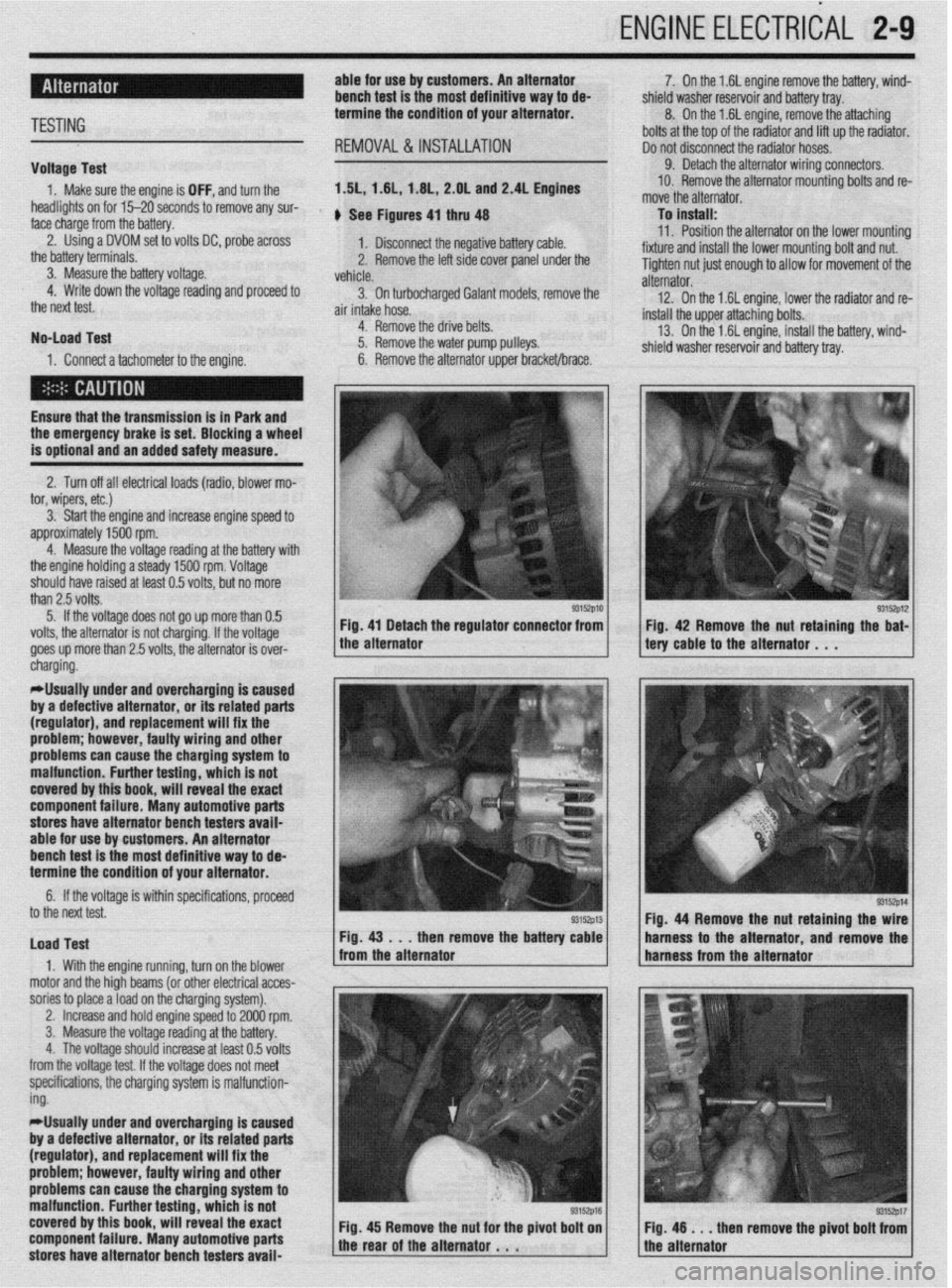
face charge from the battery. , See Figures 4, thru 48
2. Using a DVOM set to volts DC, probe across
1. Disconnect the negative battery cable.
the battery terminals.
3. Measure the battery voltage. 2. Remove the left side cover panel under the
vehicle.
4. Write down the voltage reading and proceed to
3. On turbocharaed Galant models, remove the
the next test.
air intake hose. -
No-load Test
1. Connect a tachometer to the engine. 4. Remove the drive belts.
5. Remove the water pump pulleys.
6. Remove the alternator upper bracket/brace.
Ensure that the transmission
is in Park and the emergency brake is set. Blocking a wheel
is optional and an added safety measure.
2. Turn off all electrical loads (radio, blower mo-
tor, wipers, etc.)
3. Start the engine and increase engine speed to
approximately 1500 rpm.
4. Measure the voltage reading at the battery with
the engine holding a steady 1500 rpm. Voltage
should have raised at least 0.5 volts, but no more
than 2.5 volts.
5. If the voltage does not go up more than 0.5
volts, the alternator is not charging. If the voltage
goes up more than 2.5 volts, the alternator is over-
* 7. On the 1.6L engine remove the battery, wind-
shield washer reservoir and battery tray.
8. On the 1.6L engine, remove the attaching
bolts at the top of the radiator and lift up the radiator.
Do not disconnect the radiator hoses.
9. Detach the alternator wiring connectors.
10. Remove the alternator mounting bolts and re-
move the alternator.
To install:
11. Position the alternator on the lower mountina
fixture and install the lower mounting bolt and nut. U
Tighten nut just enough to allow for movement of the
alternator.
12. On the 1.6L engine, lower the radiator and re-
install the upper attaching bolts.
13. On the 1.6L engine, install the battery, wind-
shield washer reservoir and battery tray.
/ tery cable to the alternator . , . 93152p12 Fig 42 Remove the nut retaining the bat-
cnargmg.
*Usually under and overcharging is‘caused
by a defective alternator, or its related parts
(regulator), and replacement will fix the
problem; however, faulty wiring and other
problems can
cause the charging system to
malfunction. Further testing, which is not
covered by this book, will reveal the exact
component failure. Many automotive parts
stores have alternator bench testers avaii-
able for use by customers. An alternator
bench test is the most definitive way to de-
termine the condition of your alternator.
6. If the voltage is within specifications, proceeU
to the next test.
Load Test
1. With the engine running, turn on the blower
motor and the hioh beams (or other electrical acces-
sories to place aioad on the charging system). Fig. 44 Remove the nut retaining the
then remove the batte harness to the alternator and remov
,
2. Increase and hold engine speed to 2000 rpm.
3. Measure the voltage reading at the battery.
4. The voltage should increase at least 0.5 volts
from the voltage test. If the voltage does not meet
specifications, the charging system is malfunction-
ing.
*Usually under and overcharging is caused
by a defective alternator, or its related parts
(regulator), and replacement will fix the
problem; however, faulty wiring and other
problems can cause the charging system to
malfunction. Further testing, which is not
covered by this book, will reveal the exact
component failure. Many automotive parts
stores have alternator bench testers avaii-
93152p17 en remove the pivot bolt from
Page 204 of 408
UNDERSTANDING AND
TROUBLESHOOTING
ELECTRICAL SYSTEMS 6-2
BASIC ELECTRICALTHEORY 6-2
HOW DOES ELECTRICITY WORK:
THEWATERANALOGY 6-2
OHM'S LAW 6-2
ELECTRICALCOMPONENTS 6-2
POWERSOURCE 6-2
GROUND 6-3
PROTECTIVE DEVICES 6-3
SWITCHES&RELAYS 6-3
LOAD 6-3
WIRING & HARNESSES 6-3
CONNECTORS 6-4
TEST EQUIPMENT 6-4
JUMPER WIRES 6-4
TEST LIGHTS 6-4
MULTIMETERS 6-5
TROUBLESHOOTING ELECTRICAL
SYSTEMS 6-5
TESTING 6-5
OPEN CIRCUITS 6-5
SHORT CIRCUITS 6-6
VOLTAGE 6-6
VOLTAGE DROP 6-6
RESISTANCE 6-8
WIRE AND CONNECTORREPAIR 6-6
BATTERY CABLES 6-7
DISCONNECTING THE CABLES 6-7
AIR BAG (SUPPLEMENTAL
RESTRAINT SYSTEM) 6-7
GENERALINFORMATION 6-7
SERVICE PRECAUTIONS 6-7
DISARMING 6-7
REARMING 6-7
HEATING AND AIR
CONDITIONING 6-7
BLOWER MOTOR 6-7
REMOVAL &INSTALLATION 6-7
HEATER CORE 6-9 INSTRUMENTS AND SWITCHES 6-17
INSTRUMENTCLUSTER 6-17
REMOVAL &INSTALLATION 6-17
GAUGES 6-18
REMOVAL&INSTALLATION 6-18
WINDSHIELD WIPER SWITCH 6-19
REMOVAL&INSTALLATION 6-19
REARWINDOWWIPERSWITCH 6-19
REMOVAL &INSTALLATION 6-19
DIMMER SWITCH 6-19
REMOVAL & INSTALLATION 6-19 .
HEADLIGHT SWITCH 6-19
REMOVAL & INSTALLATION 6-19
LIGHTING 6-19
HEADLIGHTS 6-19
REMOVAL &INSTALLATION 6-19
AIMINGTHEHEADLIGHTS 6-20
SIGNAL AND MARKER LIGHTS 6-21
REMOVAL &INSTALLATION 6-21
CIRCUIT PROTECTION 6-27
FUSES 6-27
REPLACEMENT 6-27
FUSIBLE LINKS 6-27
CIRCUIT BREAKERS 6-28
RESETTING AND/OR
REPLACEMENT 6-28
FLASHERS 6-28
REPLACEMENT 6-28
WIRING DIAGRAMS 6-31
REMOVAL & INSTALLATION 6-9
AIR CONDITIONING COMPONENTS 6-11
REMOVAL & INSTALLATION 6-11
CONTROLCABLES 6-12
ADJUSTMENT 6-12
CONTROL PANEL 6-12
REMOVAL & INSTALLATION 6-12
CRUISE CONTROL 6-13
ENTERTAINMENT SYSTEMS 6-14
RADIO RECEIVER/AMPLIFIER/TAPE
PLAYER/CD PLAYER 6-14
SPEAKERS 6-14
REMOVAL & INSTALLATION 6-14
WINDSHIELD WIPERS AND
WASHERS 6-15
WINDSHIELD WIPER BLADE AND
ARM 6-15
REMOVAL & INSTALLATION 6-15
WINDSHIELD WIPER MOTOR 6-16 _
REMOVAL &INSTALLATION 6-16
WINDSHIELD WASHER PUMP 6-17
REMOVAL &INSTALLATION 6-17
Page 210 of 408
I I
CHASSIS ELECTRICAL 6-7
When working on any electrical component on the
vehicle, it is always a good idea to disconnect the
negative (-) battery cable. This will prevent potential
damage to many sensitive electrical components
such as the Powertrain Control Module (PCM), radio,
alternator, etc.
*Any time you disengage the battery cables,
it is recommended that you disconnect the negative (-) battery cable first. This will pre-
vent your accidentally grounding the positive
(+) terminal to the body of the vehicle when
disconnecting it, thereby preventing damage
to the above mentioned components.
Before you disconnect the cable(s), first turn the
ignition to the OFF position. This will prevent a draw
on the battery which could cause arcing (electricity
trying to ground itself to the body of a vehicle, just
like a spark plug jumping the gap) and, of course, damaging some components such as the alternator
diodes.
When the battery cable(s) are reconnected (nega-
tive cable last), be sure to check that your lights,
windshield wipers and other electrically operated
safety components are all working correctly. If your
vehicle contains an Electronically Tuned Radio (ETR),
don’t forget to also reset your radio stations. Ditto for
the clock.
SERVICE PRECAUTIONS
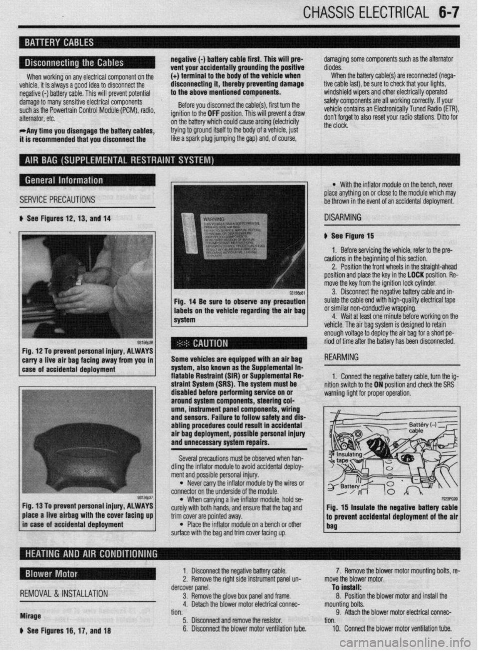
b See Figures 12,13, and 14
Fig, 14 Be sure to observe any precaution
labels on the vehicle regarding the air bag
system
Fig. 12 To prevent personal injury, ALWAYS
*
carry a-live -ah bag fac!ng away from you in 1
1 case of accidental deployment Some vehicles are equipped wtth an air bag
-.-‘--
syr1em, aiscl Known as I11 -I-- ‘------- -- sLe Supplemental in- fiatable Restraint (SIR) o r Suouiementai Fiea
l With the inflator module on the bench, never
place anything on or close to the module which may
be thrown in the event of an accidental deployment.
DISARMING
# See Figure 15
1. Before servicing the vehicle, refer to the pre-
cautions in the beginning of this section.
2. Position the front wheels in the straight-ahead
position and place the key in the LOCK position. Re-
move the key from the ignition lock cylinder.
3. Disconnect the negative battery cable and in-
sulate the cable end with high-quality electrical tape
or similar non-conductive wrapping.
4. Wait at least one minute before working on the
vehicle. The air baa svstem is desianed to retain
enough voltage to deploy the air bag for a short pe-
riod of time after the battery has been disconnected.
1. Connect the neoative batters cable. turn the ia-
3, hold se-
e bag and
trim cover are pointed away.
l Place the inflator module on a bench or other
surface with the bag and trim cover facing up.
7!r!3PG93 Fig. 15 insulate the negative battery cable
.I
to prevent accidental deployment of the air
bag place a live airbag with the cover facing up
in case of accidental deployment
REMOVAL &INSTALLATION
Mirage
b See Figures 16, 17, and 18 1. Disconnect the negative battery cable.
2. Remove the right side instrument panel un-
dercover panel.
3. Remove the glove box panel and frame.
4. Detach the blower motor electrical connec-
tion.
5. Disconnect and remove the resistor.
6. Disconnect the blower motor ventilation tube. 7. Remove the blower motor mounting bolts, re-
move the blower motor.
To install:
8. Position the blower motor and install the
mounting bolts.
9. Attach the blower motor electrical connec-
tion.
10. Connect the blower motor ventilation tube.
Page 212 of 408
CHASSIS ELECtRldAL 6-9
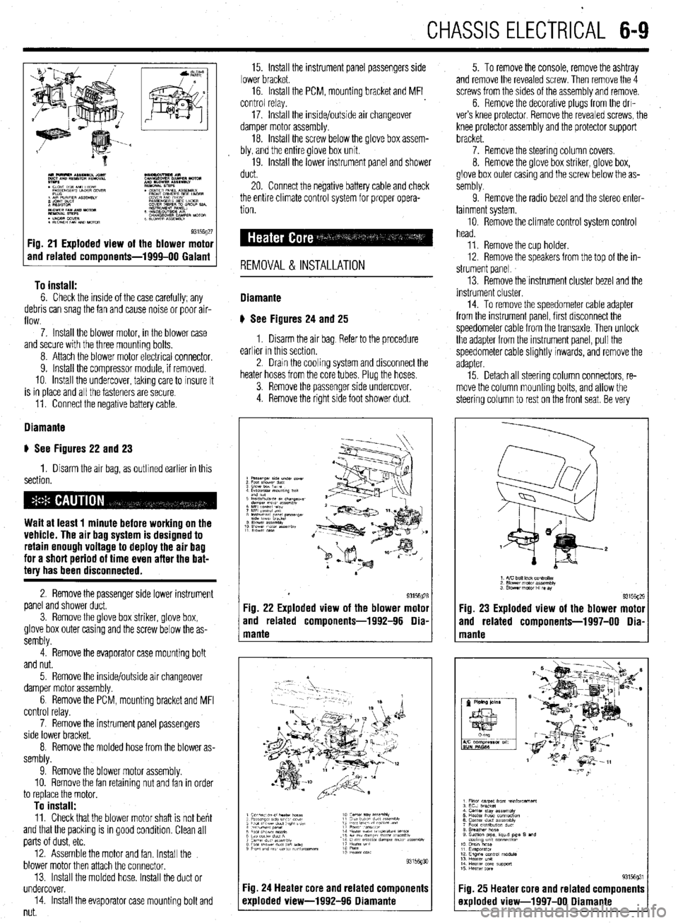
93156g27 Fig. 21 Exploded view of the blower motor
and related components-1999-00 Galant
To install:
6. Check the inside of the case carefully; any
debris can snag the fan and cause noise or poor air-
flow.
7. Install the blower motor, in the blower case
and secure with the three mounting bolts,
8. Attach the blower motor electrlcal connector,
9. Install the compressor module, if removed.
10. Install the undercover, takmg care to insure it
is in place and all the fasteners are secure.
11. Connect the negative battery cable.
Diamante
u See Figures 22 and 23
1. Disarm the air bag, as outlined earlier in this
section.
Wait at least 1 minute before working on the
vehicle. The air bag system is designed to
retain enough voltage to deploy the air bag
for a short period of time even after the bat-
tery has been disconnected.
2. Remove the passenger side lower instrument
panel and shower duct,
3. Remove the glove box striker, glove box,
glove box outer casing and the screw below the as-
sembly.
4. Remove the evaporator case mounting bolt
and nut.
5. Remove the inside/outside air changeover
damper motor assembly.
6 Remove the PCM, mounting bracket and MFI
control relay.
7. Remove the instrument panel passengers
side lower bracket.
8. Remove the molded hose from the blower as-
sembly.
9. Remove the blower motor assembly.
10. Remove the fan retaining nut and fan in order
to replace the motor,
To install: 11. Check that the blower motor shaft is not bent
and that the packing is in good condition, Clean all
parts of dust, etc.
12. Assemble the motor and fan. Install the
blower motor then attach the connector.
13. Install the molded hose. Install the duct or
undercover.
14. Install the evaporator case mounting bolt and
nut. 15. Install the instrument panel passengers side
lower bracket.
16. Install the PCM, mounting bracket and MFI
control relay.
17. Install the inside/outside air changeover
damper motor assembly.
18. Install the screw below the glove box assem-
bly, and the entire glove box unit.
19. Install the lower instrument panel and shower
duct.
20. Connect the negative battery cable and check
the entire climate control system for proper opera-
tion.
REMOVAL & INSTALLATION
Diamante
u See Figures 24
and 25
1. Disarm the air bag Refer to the procedure
earlier in this section.
2. Dram the cooling system and disconnect the
heater hoses from the core tubes. Plug the hoses.
3. Remove the passenger side undercover.
4. Remove the right side foot shower duct. 5. To remove the console, remove the ashtray
and remove the revealed screw. Then remove the 4
screws from the sides of the assembly and remove.
6. Remove the decorative plugs from the drl-
ver’s knee protector. Remove the revealed screws, the
knee protector assembly and the protector support
bracket.
7. Remove the steering column covers.
8. Remove the glove box striker, glove box,
glove box outer casing and the screw below the as-
sembly.
9. Remove the radio bezel and the stereo enter-
tainment system.
10. Remove the climate control system control
head.
11. Remove the cup holder.
12. Remove the speakers from the top of the in-
strument panel.
13. Remove the instrument cluster bezel and the
instrument cluster.
14. To remove the speedometer cable adapter
from the instrument panel, first disconnect the
speedometer cable from the transaxle. Then unlock
the adapter from the instrument panel, pull the
speedometer cable slightly inwards, and remove the
adapter
15. Detach all steering column connectors, re-
move the column mounting bolts, and allow the
steering column to rest on the front seat. Be very
Fig. 23 Exploded view of the blower motor
and related components-1997-00 Dia-
Fig. 25 Heater core and related components
exploded view-1997-00 Diamante
Page 214 of 408
CHASSIS ELECTRICAL 6-11
45. Install the heater hoses under the hood.
46. Install the mstrument panel by reversing its
removal procedure.
47. Install the center console.
48. install the upper and lower steering column
covers.
49. Install the center panel undercover.
50. Install the small column panel.
51. Install the steering wheel.
52. Fill the cooling system.
53. Connect the negative battery cable and check
the entire climate control system for proper operation
and leaks.
Mirage
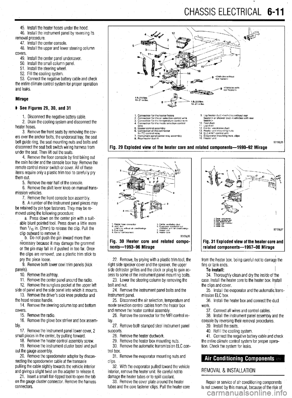
# See Figures 29, 30, and 31
1. Disconnect the negative battery cable.
2. Drain the cooling system and disconnect the
heater hoses.
3. Remove the front seats by removing the cov-
ers over the anchor bolts, the underseat tray, the seat
belt guide ring, the seat mounting nuts and bolts and
disconnect the seat belt switch wiring harness from
under the seat. Then lift out the seats
4. Remove the floor console by first taking out
the coin holder and the console box tray. Remove the
remote control mirror switch or cover. All of these
items require only a plastic trim tool to carefully pry
them out.
5. Remove the rear half of the console.
6. Remove the shift lever knob on manual trans-
mission vehicles.
7. Remove the front console box assembly.
8. A number of the instrument panel pieces may
be retamed by pin type fasteners. They may be re-
moved using the following procedure:
a. Press down on the center pin with a suit-
able blunt pointed tool. Press down a little more
than l/re in. (2mm) to release the clip. Pull the
clip outward to remove it.
b. Do not oush the oin inward more than
necessary because it may damage the grommet
or the pin may fall in if pushed in too far. Once
the clips are removed, use a plastic trim stick to
pry the piece loose.
9. Remove both lower cowl trim panels (kick
panels).
10. Remove the ashtray.
11. Remove the center panel around the radio.
12. Remove the sunglass pocket at the upper left
side of panel and the side panel into which it mounts,
13. Remove the drivers side knee protector and
the hood release handle.
14. Remove the steering column top and bottom
covers.
15. Remove the radio.
16. Remove the glove box striker and box assem-
bly.
17. Remove the instrument panel lower cover, 2
small pieces in the center, by pulling forward.
18. Remove the heater control assembly screw.
19. Remove the instrument cluster bezel and pull
out the Qauge assembly.
20. Remove the speedometer adapter by discon-
necting the speedometer cable at the transaxle
pulling the cable Sightly towards the vehicle interior
and giving a Slight twist on the adapter to release it.
21. Insert a small flat-tipped tool to open the tab
on the QauQe cluster connector. Remove the harness
connectors.
Fig. 29 Exploded view of the heater core and related components-1990-92 Mirage
93l%Q% Fig. 30 Heater core and related compo-
nents-1993-96 Mirage
22. Remove, by prying with a plastic trim tool, the
right side speaker cover and the speaker, the upper
side defroster grilles and the clock or plug to gain ac-
cess to some of the instrument panel mounting bolts.
23. Lower the steering column by removing the
bolt and nut.
24. Remove the instrument panel bolts and the
instrument panel.
25 Drsconnect the air selection, temperature and
mode selection control cables from the heater box
and remove the heater control assembly.
26. Remove the connector for the MFI control re-
lay.
27. Remove both stamped steel instrument panel
supports.
28. Remove the heater ductwork.
29. Remove the heater box mounting nuts.
30 Remove the automatic transmission ELC con-
trol box.
31. Remove the evaporator mounting nuts and
clips.
32. With the evaporator pulled toward the vehicle
interior, remove the heater unit. Be careful not to
damage the heater tubes or to spill coolant.
33. Remove the cover plate around the heater
tubes and the core fastener clips. Pull the heater core 34. Thoroughly clean and dry the inside of the
case. Install the heater core to the heater box. Install
the clips and cover,
35. Install the evaporator and the automatic trans-
mission ELC box.
36. Install the heater box and connect the duct
Fig. 31 Exploded view of the heater core and
related components-1997-00 Mirage
from the heater box, being careful not to damage the
fins or tank ends.
To install: I
work.
37. Connect all wires and control cables,
38. Install the instrument panel assembly and the
console by reversmg their removal procedures.
39 Install the seats.
40. Refill the cooling system.
41. Connect the negative battery cable and check
the entire climate control system for proper opera-
tion Check the system for leaks.
REMOVAL &INSTALLATION
Repair or service of air Conditioning components
is not covered by this manual, because of the risk of
Page 215 of 408
6-12 CHASSIS ELECTRICAL
personal injury or death, and because of the legal
ramifications of servicing these components without
the proper EPA certification and experience. Cost,
personal injury or death, environmental damage, and
legal considerations (such as the fact that it is a fed-
eral crime to vent refrigerant into the atmosphere),
dictate that the A/C comoonents on your vehicle 4. Move the air selection controi lever to the RE-
CIRC position. Move the air selection damper FULLY
INWARD and connect the cable to the lever. Adjust as
required. C. Push the outer cable in the direction of the
arrow so that there is no looseness, then secure
should be serviced only’by a Motor Vehicle Air Con-
ditioning (MVAC) trained, and EPA certified automo-
REMOVAL&INSTALLATION tive technician. with the clip.
d. Set the knob for the air outlet changeover
on the control to the DEF position.
e. Set the air outlet changeover damper lever
of the heater unit to the DEF position, then attach
the cable to the lever pin.
f. Push the outer cable in the direction of the
arrow so there is no loosen&s, then secure it
with the clip. *If your vehicle’s A/C system uses R-12 re-
frlgerant and is in need of recharging, the
AK system can be converted over to R-Ma
refrigerant (less environmentally harmful
and expensive). Refer to Section 1 for addi-
tional information on R-12 to R-134a eonver-
sions, and for additional considerations
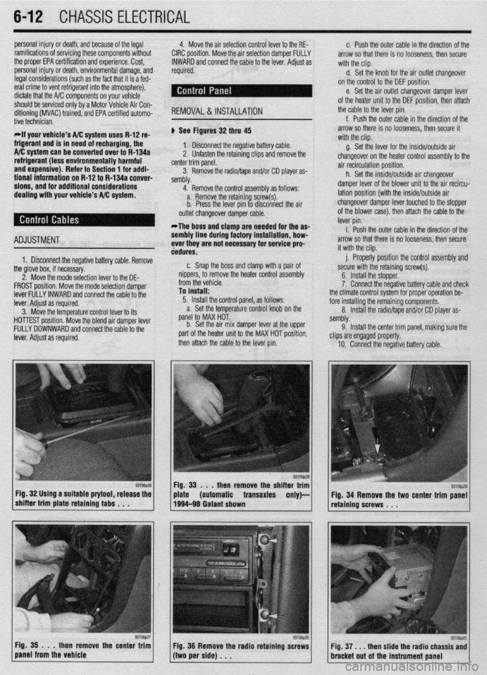
dealing with your vehicle’s A/C system. ti See Figures 32 thru 45
1. Disconnect the negative battery cable.
2, Unfasten the retaining clips and remove the
center trim panel.
3. Remove the radioltape and/or CD player as-
sembly,
4. Remove the control assembly as follows:
a. Remove the retaining screw(s).
b. Press the lever pin to disconnect the air
outlet changeover damper cable.
*The boss and clamp are needed for the as-
ADJUSTMENT
1. Disconnect the negative battery cable. Remove sembly line d
ever they are
dedures.
n Cnan i luring factory installation, how-
not necessary for service pro-
the glove box, if necessary,
2. Move the mode selection lever to the DE-
FROST position. Move the mode selection damper
lever FULLY INWARD and connect the cable to the
lever. Adiust as required.
3. M&e tht
3 temperature control lever to its
HOlli
5ST position. Move the blend air damper lever
FULL’t
’ DOWNWARD and connect the cable to the
lever. i
4djust as required. b,. dIIal, the boss and clamp with a pair of
nippers, to remove the heater control assembly
from the vehicle.
To install:
5. Install the control panel, as follows:
a. Set the temperature control knob on the
panel to MAX HOT..
b. Set the air mix damper lever at the upper
part of the heater unit to the MAX HOT position,
then attach the cable to the lever pin.
then remove the shi
Fig. 32 Using a suitable prytool, release the
automatic transaxles
93156p27 Fig. 35 . . .
then remove the center trim
panel from the vehicle
/(twiperside)... y Fig 36 Remove the radio retaining screws g. Set the lever for the inside/outside air
changeover on the heater control assemblv to the
air recirculation position.
h. Set the inside/outside air changeover
damper lever of the blower unit to the air recircu-
lation position (with the inside/outside air
changeover damper lever touched to the stopper
of the blower case), then attach the cable to the
lever pin.
i. Push the outer cable in the direction of the
arrow so that there is no looseness, then secure
it with the clip.
j. Properly position the control assembly and
secure with the retaining screw(s).
6. Install the stopper.
7. Connect the negative battery cable and check
the climate control system for proper operation be-
fore installing the remaining components.
8. Install the radio/tape and/or CD player as-
sembly.
9. Install the center trim oanel, makina sure the
clips are engaged properly. -
10. Connect the negative battery cable.
Fig. 34 Remove the two center trim panel
retaining screws . . .
Fig. 37, . . then slide the radio chassis and
bracket out of the instrument Dane1
Page 216 of 408
CHASSIS ELECTRICiL 6-13
.
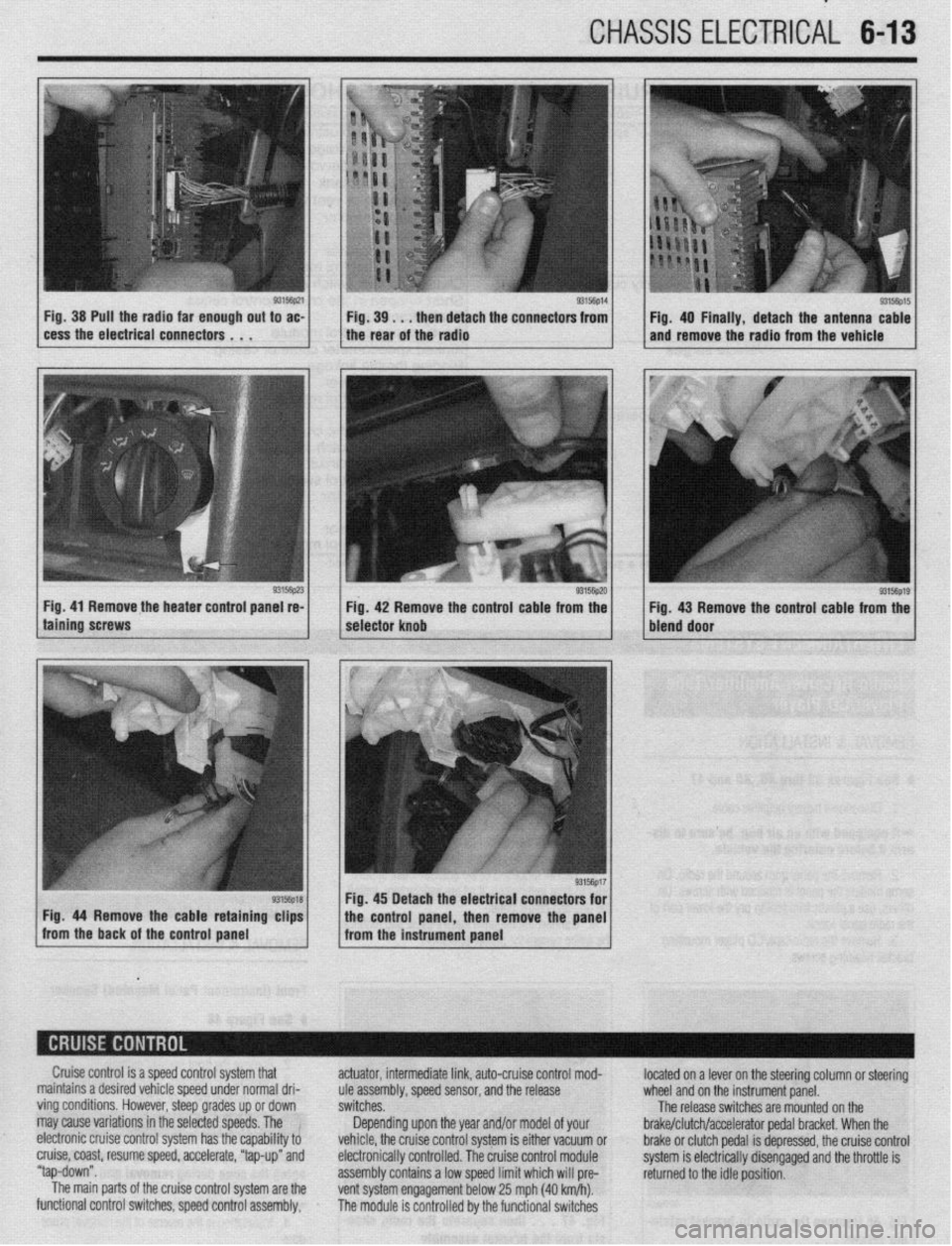
Fig. 38 Pull the radia far enough out to ac-
cess the electrical connectors . . . 9315fip14 Fig. 39. . . then detach the connectors from
I I Fig. 40 Finally, detach the antenna cable
the rear of the radio and remove the radio from the vehicle
Fig. 41 Remove the heater control panel re-
Fig. 42 Remove the control cable from the
g3156p1g / Fig 43 Remove the control cable from the
bleid door
Cruise control is a speed control system that
maintains a desired vehicle speed under normal dri-
ving conditions. However, steep grades up or down
may cause variations in the selected speeds. The !
electronic cruise control system has the capability to
cruise, coast, resume speed, accelerate, “tap-up” and
“tap-down”.
The main parts of the cruise control system are the
functional control switches, speed control assembly, actuator, intermediate link, auto-cruise control mod-
ule assembly, speed sensor, and the release
switches.
Depending upon the year and/or model of your
vehicle, the cruise control system is either vacuum or
electronically controlled. The cruise control module
assembly contains a low speed limit which will pre-
vent system engagement below 25 mph (40 km/h).
The module is controlled by the functional switches located on a lever on the steering column or steering
wheel and on the instrument panel.
The release switches are mounted on the
brake/clutch/accelerator pedal bracket. When the
brake or clutch pedal is depressed, the cruise control
system is electrically disengaged and the throttle is
returned to the idle position.
Page 217 of 408
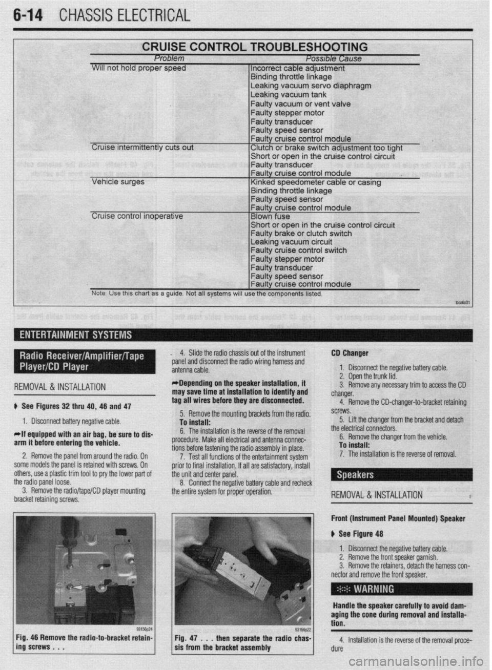
6-14 CHASSIS ELECTRICAL
CRUISE CONTROL TROUBLESHOOTING Problem Posable Cause
WIII not hold proper speed 1 Incorrect cable adjustment
F.~. _I.~_ - 1L .-AL‘- I. I -
Cruise intermittently cuts out
trrnarng Inrome nnKage Leaking vacuum servo diaphragm
Leaking vacuum tank
Faulty vacuum or vent valve
Faulty stepper motor
Faulty transducer
Faulty speed sensor
Faulty cruise control module
‘ Clutch or brake switch adjustment too tight -chnrt *r nna* in the cruise control circuit
cer VI I”, . vt “y”‘,
I- Faulty transdu
Leaking vacuum circuit Faulty cruise control switch
Faulty stepper motor
Note. Use this chart as a guide. Not all systems will use the components listed.
t-,
I ,-- ,
REMOVAL&INSTALLATION
# See Figures 32 thru 40, 46 and 47
1. Disconnect battery negative cable.
*If equipped with an air bag, be sure to dis-
arm it before entering the vehicle.
2. Remove the panel from around the radio, On
some models the panel is retained with screws, On
others, use a plastic trim tool to pry the lower pad of
the radio panel loose.
3. Remove the radio/tape/CD player mounting
bracket retaining screws, 4. Slide the radio chassis out of the instrument
*panel and disconnect the radio wiring harness and
*Depending on the speaker installation, it
may save time at installation to identify and
tag all wires before they are disconnected.
5. Remove the mounting brackets from the radio.
To install:
6. The installation is the reverse of the removal
procedure. Make all electrical and antenna connec-
tions before fastening the radio assembly in place.
7. Test all functions of the entertainment system
prior to final installation. If all are satisfactory, install
the unit and center panel.
8. Connect the negative battery cable and recheck
the entire system for proper operation. CD Changer
1. Disconnect the negative battery cable.
2. Open the trunk lid.
3. Remove any necessary trim to access the CD
changer.
4. Remove the CD-changer-to-bracket retaining
screws.
5. Lift the changer from the bracket and detach
the electrical connectors.
6. Remove the changer from the vehicle.
To install:
7. The installation is the reverse of removal.
REMOVAL&INSTALLATION l
Front (Instrument Panel Mounted) Speaker
u See Figure 48
1. Disconnect the negative battery cable.
2. Remove the front speaker garnish.
3. Remove the retainers, detach the harness con-
nector and remove the front speaker,
Handle the speaker carefully to avoid dam-
aging the cone during removal and installa-
tion.
4. Installation is the reverse of the removal proce-
dure
Page 233 of 408
6-30 CHASSIS ELECTRICAL
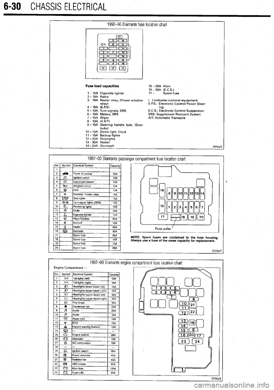
1992-96 Diamante fuse location chart
I
Fuse load caaacities 15 -2OA Horn
16 - 20A (E.C.S.)
1 - 15A Cigarette lighter 17 - spare fuse
2 - 10A Radio
3 - 10A Heater relay, (Power window ( ) indicates optlonal equipment
relay) E P.S.: Electronic Control Power Steer-
4 - 10A (E.P.S) ing
5 - 10A Turn signals, SRS E.C.S.: Electronic Control Suspension
6 - 10A Meters, SRS SRS~ Supplement Restratnt System
7 - 15A Wiper A/T: Automatic Transaxle
8-10A (4AIT)
9- 15A Steering handle lock, (Door
locks)
lo- 10A Dome light, Clock
11 - 10A Backup lights
12 -2OA StoplIghts
13 -3OA Heater
14 - 20A (Sunroof)
93156fllE
1997-00 Diamante passenger compartment fuse location chart No Symbol Electrical System
I capactty
I
Spare fuses are contained in the fuse housing
use a fuse of the same capacity for replacement.
199740 Diamante encline
compartment fuse location chart