flat tire MITSUBISHI DIAMANTE 1900 User Guide
[x] Cancel search | Manufacturer: MITSUBISHI, Model Year: 1900, Model line: DIAMANTE, Model: MITSUBISHI DIAMANTE 1900Pages: 408, PDF Size: 71.03 MB
Page 297 of 408

.
8-2 SUSPENSION AND STEERING
b
REMOVAL &INSTALLATION
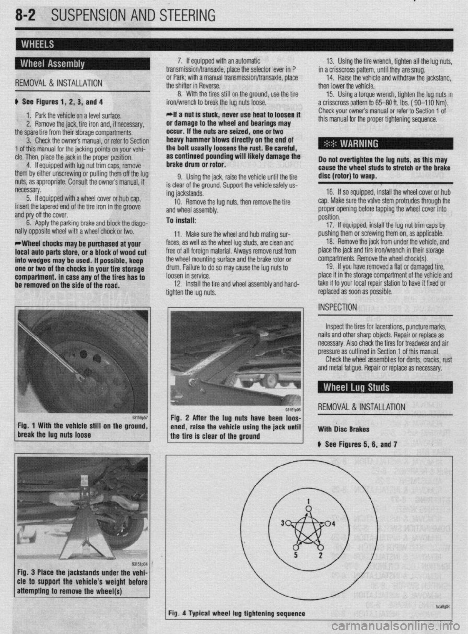
# See Figures 1, 2, 3, and 4
1. Park the vehicle on a level surface.
2. Remove the jack, tire iron and, if necessary,
the spare tire from their storage compartments.
3. Check the owners manual, or refer to Section
1 of this manual for the jacking points on your vehi-
cle. Then, place the jack in the proper position,
4. If equipped with lug nut trim caps, remove
them by either unscrewing or pulling them off the lug
nuts, as appropriate. Consult the owners manual, if
necessary.
5. If equipped with a wheel cover or hub cap,
insert the tapered end of the tire iron in the groove
and pry off the cover.
6. Apply the parking brake and block the diago-
nally opposite wheel with a wheel chock or two.
*Wheel chocks may be purchased at your
local auto parts store, or a block of wood cut
into wedges may be used. If possible, keep
one or two of the chocks in your tire storage
compartment, in case any of the tires has to
be removed on the side of the road. 7. If equipped with an automatic
transmission/transaxle, place the selector lever in P
or Park; with a manual transmission/transaxle, place
the shifter in Reverse.
8. With the tires still on the ground, use the tire
iron/wrench to break the lug nuts loose.
*If a nut is stuck, never use heat to loosen it
or damage to the wheel and bearings may
occur. If the nuts are seized, one or two
heavy hammer blows directly on the end of
the bolt usually loosens the rust. Be careful,
as continued pounding will likely damage the
brake drum or rotor.
9. Using the jack, raise the vehicle until the tire
is clear of the ground. Support the vehicle safely us-
ing jackstands.
10. Remove the lug nuts, then remove the tire
and wheel assembly.
To install:
11. Make sure the wheel and hub mating sur-
faces, as well as the wheel lug studs, are clean and
free of all foreign material. Always remove rust from
the wheel mounting surface and the brake rotor or
drum. Failure to do so may cause the lug nuts to
loosen in service.
12. Install the tire and wheel assembly and hand-
tighten the lug nuts. 13. Using the tire wrench, tighten all the lug nuts,
in a crisscross pattern, until they are snug.
14. Raise the vehicle and withdraw the jackstand,
then lower the vehicle.
15. Using a torque wrench, tighten the lug nuts in
a crisscross pattern to 65-80 ft. lbs. ( 90-l 10 Nm).
Check your owners manual or refer to Section 1 of
this manual for the proper tightening sequence.
Do not overtighten the lug nuts, as this may
cause the wheel studs to stretch or the brake
disc (rotor) to warp.
16. If so equipped, install the wheel cover or hub
cap. Make sure the valve stem protrudes through the
proper opening before tapping the wheel cover into
position.
17. If equipped, install the lug nut trim caps by
pushing them or screwing them on, as applicable.
18. Remove the jack from under the vehicle, and
place the jack and tire iron/wrench in their storage
compartments. Remove the wheel chock(s).
19. If you have removed a flat or damaged tire,
place it in the storage compartment of the vehicle and
take it to your local repair station to have it fixed or
replaced as soon as possible.
Inspect the tires for lacerations, puncture marks,
nails and other sharp objects. Repair or replace as
necessary. Also check the tires for treadwear and air
pressure as outlined in Section 1 of this manual.
Check the wheel assemblies for dents, cracks, rust
and metal fatigue. Repair or replace as necessary.
REMOVAL&INSTALLATION
Fig. 3 Place the jackstands under the vehi-
cle to support the vehicle’s weight before
Page 311 of 408

8116 SUSPENSION AND STEERING
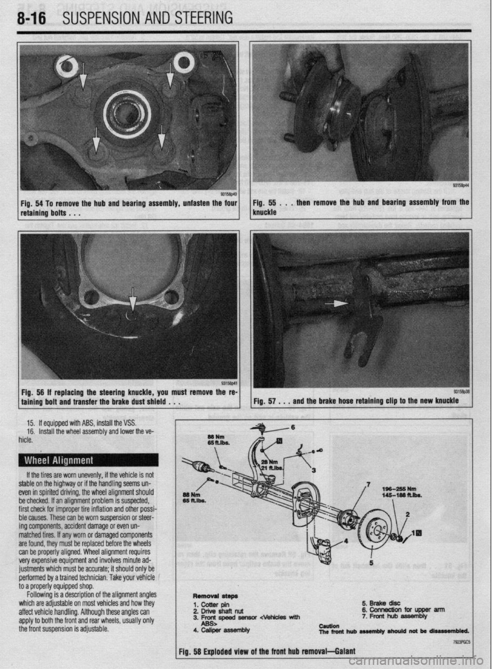
Fig. 54 To remove the hub and bearing assembly, unfasten the four Fig. 55 . . . then remove the hub and bearing assembly from the
retaining bolts . . . knuckle
Fig, 56 If replacing the steering knuckle, you must remove the re-
taining bolt and transfer the brake dust shield . . .
15. If equipped with ABS, install the VSS.
16. Install the wheel assembly and lower the ve-
hicle.
If the tires are worn unevenly, if the vehicle is not
stable on the highway or if the handling seems un-
even in spirited driving, the wheel alignment should
be checked. If an alignment problem is suspected,
first check for improper tire inflation and other possi-
ble causes. These can be worn suspension or steer-
ing components, accident damage or even un-
matched tires. If any worn or damaged components
are found, they must be replaced before the wheels
can be properly aligned. Wheel alignment requires
very expensive equipment and involves minute ad-
justments which must be accurate; it should only be
performed by a trained technician. Take your vehicle
to a properly equipped shop.
Following is a description of the alignment angles
which are adjustable on most vehicles and how they
affect vehicle handling. Although these angles can
apply to both the front and rear wheels, usually only
the front suspension is adjustable.
5.BrakediW
2. Drive shafl nut &collnectionfciflJpperarm
3. Frc-rc,speed fiensor cvehides with 7. Front hub assembly
4. Caliper asWmbly cauuen
nlcrfonthubaMmbly~natbrrliurr#n61ed.
Page 407 of 408

MASTER INDEX 11-25 -
REAROUTPUTSHAFTSEAL 7-14
TESTING 6-5
REMOVAL & INSTALLATION 7-14
' THERMOSTAT 3-7
REAR SUSPENSION 8-18 REMOVAL & INSTALLATION 3-7
REAR WINDOW WIPER SWITCH 6-19 THROTTLE BODY 5-3
REMOVAL&INSTALLATION 6-19 REMOVAL & INSTALLATION 5-3
REARDRlVEAXLE(AWDGALANTONLY) l-38
THROTTLEPOSITIONSENSOR 4-13
DRAIN &REFILL 1-38
OPERATION 4-13
FLUIDRECOMMENDATIONS 1-38 , REMOVAL&INSTALLATION 4-13
LEVELCHECK l-38
TESTING 4-13
REGULATOR 2-10 TIMING COVERAND BELT 3-36
REMOVAL&INSTALLATION 2-10
INSPECTION 3-48
RELIEVING FUELSYSTEM PRESSURE 5-3 REMOVAL & INSTALLATION 3-36
ROCKERARM(VALVE)COVER 3-1
TIMING BELTS l-20
REMOVAL & INSTALLATION 3-1
INSPECTION I-20
ROCKER ARM/SHAFTS 3-4
TIRESANDWHEELS I-30
REMOVAL & INSTALLATION 3-4
CAREOFSPECIALWHEELS l-32
ROUTINE MAINTENANCE AND TUNE-UP 1-14 INFLATION & INSPECTION I-31
SEATS IO-IO
TIRE DESIGN I-31
REMOVAL&INSTALLATION IO-IO TIRE ROTATION I-30
SENDING UNITS 2-11
TIRESTORAGE I-31
SERIAL NUMBER IDENTIFICATION l-10
TONE (EXCITER) RING 9-29
SERVICING YOUR VEHICLE SAFELY I-4
REMOVAL & INSTALLATION 9-29
SHOCKABSORBERAND COILSPRING 8-8
TOOLS AND EQUIPMENT 1-2
OVERHAUL 8-9
TORQUE 1-7
REMOVAL&INSTALLATION 8-8 TORQUEANGLEMETERS l-9
SIGNAL AND MARKER LIGHTS 6-21
TORQUEWRENCHES l-7
REMOVAL & INSTALLATION 6-21
TOWING THE VEHICLE 1-44
SPARKPLUG WIRES 1-24
TRAINING ARM 8-24
REMOVAL&INSTALLATION 1-24
REMOVAL & INSTALLATION 8-24
TESTING 1-24
TRANSAXLEIDENTIFICATION I-10
SPARKPLUGS l-22
TRANSFER CASE ASSEMBLY 7-14
INSPECTION &GAPPING l-23
REMOVAL & INSTALLATION 7-14
REMOVAL&INSTALLATION 1-22
TRANSFER CASE 7-14
SPARKPLUGHEATRANGE 1-22
TRANSFERCASE(AWD GALANT ONLY) 1-38
SPEAKERS 6-14
DRAIN &REFILL 1-38
REMOVAL & INSTALLATION 6-14
FLUIDRECOMMENDATIONS 1-38
SPECIALTOOLS 1-4
LEVELCHECK 1-38
SPEED SENSORS 9-28
TRANSFERCASE(AWDGALANTONLY) I-10
REMOVAL & INSTALLATION 9-28
TROUBLESHOOTING ELECTRICALSYSTEMS 6-5
STANDARDANDMETRIC MEASUREMENTS l-9
OPEN CIRCUITS 6-5
STARTER 2-10
RESISTANCE 6-8
REMOVAL&INSTALLATION 2-11
SHORT CIRCUITS 6-6
TESTING 2-10
VOLTAGEDROP 6-6
STARTING SYSTEM 2-10
VOLTAGE 6-6
STEERING LINKAGE 8-30
TRUNK LID IO-3
REMOVAL &INSTALLATION 8-30
ALIGNMENT IO-3
STEERING WHEEL 8-27
REMOVAL & INSTALLATION IO-3
REMOVAL &INSTALLATION 8-27
TURBOCHARGER 3-17
STEERING 8-27
REMOVAL & INSTALLATION 3-17
STRUT AND COIL SPRING
8-21
UNDERSTANDING AND TROUBLESHOOTING ELECTRICAL
OVERHAUL 8-22
SYSTEMS 6-2
REMOVAL & INSTALLATION 8-21
UNDERSTANDINGTHEAUTOMATICTRANSAXLE 7-10
STUBAXLESHAFT,BEARlNG AND SEAL 7-15
REMOVAL & INSTALLATION 7-10
REMOVAL&INSTALLATION 7-15
UNDERSTANDINGTHECLUTCH 7-7
SWAY BAR 8-12
ADJUSTMENTS 7-8
REMOVAL 8, INSTALLATION 8-12
REMOVAL&INSTALLATION 7-7
SWAY BAR 8-25
UNDERSTANDINGTHE MANUALTRANSAXLE 7-2
REMOVAL&INSTALLATION 8-25
SHIFT LINKAGE 7-2
TAILGATE/HATCH HANDLE lo-19
UPPER BALLJOINT 8-9
REMOVAL &INSTALLATION lo-10
INSPECTION 8-9
TAILGATE IO-3
REMOVAL &INSTALLATION 8-9
ALIGNMENT IO-3 i'
UPPER CONTROLARM 8-10
REMOVAL & INSTALLATION IO-3
REMOVAL & INSTALLATION 8-10
TANKASSEMBLY 5-10
UPPER CONTROL ARMS 8-22
REMOVAL&INSTALLATION 5-10
REMOVAL & INSTALLATION 8-22
TEST EQUIPMENT 6-4
VACUUM DIAGRAMS 4-36
JUMPER WIRES 6-4
VALVE LASH 1-27
MULTIMETERS 6-5
ADJUSTMENT 1-27
TEST LIGHTS 6-4
VEHICLE IDENTIFICATION NUMBER I-10