light MITSUBISHI DIAMANTE 1900 User Guide
[x] Cancel search | Manufacturer: MITSUBISHI, Model Year: 1900, Model line: DIAMANTE, Model: MITSUBISHI DIAMANTE 1900Pages: 408, PDF Size: 71.03 MB
Page 32 of 408
GENERALINFORMATIONAND MAINTENANC-E 1133
Used fluids such as engine oil, transaxle fluid, an-
tifreeze and brake fluid are hazardous wastes and
must be disposed of properly. Before draining any
fluids, consult with your local authorities; in many ar-
eas, waste oil, antifreeze, etc. is being accepted as a
part of recycling programs. A number of service sta-
tions and auto parts stores are also accepting waste
fluids for recycling.
Be sure of the recycling center’s policies before
draining any fluids, as many will not accept different
fluids that have been mixed together.
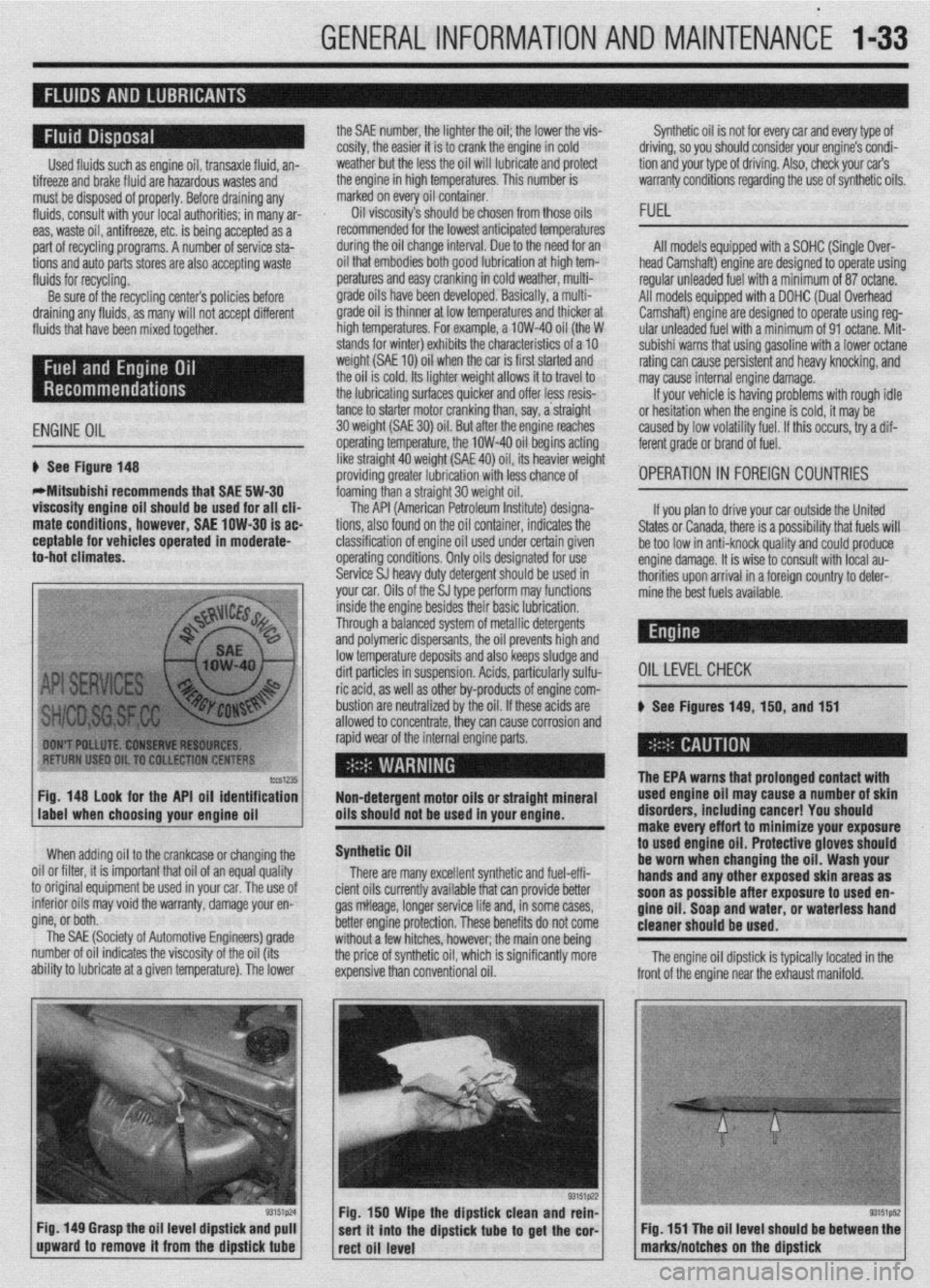
ENGINE OIL
6 See Figure 148
WMitsubishi recommends that SAE 5W-30
viscosity engine oil should be used for all clia
mate conditions, however, SAE low-30 is ac
ceptable for vehicles operated in moderate-
to-hot climates. the SAE number, the lighter the oil; the lower the vis-
cosity, the easier it is to crank the engine in cold
weather but the less the oil will lubricate and protect
the engine in high temperatures. This number is
marked on every oil container.
Oil viscosity’s should be chosen from those oils
recommended for the lowest anticipated temperatures
during the oil change interval. Due to the need for an
oil that embodies both good lubrication at high tem-
peratures and easy cranking in cold weather, multi-
grade oils have been developed. Basically, a multi-
grade oil is thinner at low temperatures and thicker at
high temperatures. For example, a low-40 oil (the W
stands for winter) exhibits the characteristics of a 10
weight (SAE 10) oil when the car is first started and
the oil is cold. Its lighter weight allows it to travel to
the lubricating surfaces quicker and offer less resis-
tance to starter motor cranking than, say, a straight
30 weight (SAE 30) oil. But atier the ensine reaches
operating temperature, the low-40 oil begins acting
like straight 40 weight (SAE 40) oil, its heavier weight
providing greater lubrication with less chance of
foaming than a straight 30 weight oil. Synthetic oil is not for every car and every type of
driving, so you should consider your engine’s condi-
tion and your type of driving. Also, check your car’s
warranty conditions regarding the use of synthetic oils.
FUEL
All models equipped with a SOHC (Single Over-
head Camshaft) engine are designed to operate using
regular unleaded fuel with a minimum of 87 octane.
All models equipped with a DOHC (Dual Overhead
Camshaft) engine are designed to operate using reg-
ular unleaded fuel with a minimum of 91 octane. Mit-
subishi warns that using gasoline with a lower octane
rating can cause persistent and heavy knocking, and
may cause internal engine damage.
If your vehicle is having problems with rough idle
or hesitation when the enoine is cold, it mav be
caused by low volatility fuel. If this occurs, iry a dif-
ferent grade or brand of fuel.
'OPERATION 1~ FOREIGN COUNTRIES
lccS1235 Fig. 148 look for the API oil identification
Non-detergent motor oils or straight mineral
label when choosing your enaine oil oils should not be used in your engine.
When adding oil to the crankcase or changing the
0 Nil or filter, it is important that oil of an equal quality
I original equipment be used in your car. The use of
. tc mtenor 011s may void the warranty, damage your en-
gine, or both. __
The SAE (Society of Automotive Engineers) grade
number of oil indicates the viscosity of the oil (its
ability to lubricate at a given temperature). The lower
Fig. 149 Grasp the oil level dipstick and pull
upward to remove it from the dipstick
tube
The API (American Petroleum Institute) designa-
tions, also found on the oil container, indicates the
classification of engine oil used under certain given
operating conditions. Only oils designated for use
Service SJ heavy duty detergent should be used in
your car. Oils of the SJ type perform may functions If you plan to drive your car outside the United
States or Canada, there is a possibility that fuels will
be too low in anti-knock quality and could produce
engine damage. It is wise to consult with local au-
thorities upon arrival in a foreign country to deter-
mine the best fuels available.
inside the engine besides their basic lubrication.
Through a balanced system of metallic detergents
and polymeric dispersants, the oil prevents high and
low temperature deposits and also keeps sludge and
dirt particles in suspension. Acids, particularly sulfu-
OILLEVELCHECK ric acid, as well as other by-products of engine com-
bustion are neutralized by the oil. If these acids are
# See Figures 149, 150, and 151
allowed to concentrate, thev can cause corrosion and
rapid wear of the internal engine parts.
Synthetic Oil
There are many excellent synthetic and fuel-effi-
cient oils currently available that can provide better
gas mileage, longer service life and, in some cases,
better engine protection. These benefits do not come
without a few hitches, however; the main one being
the price of synthetic oil, which is significantly more
expensive than conventional oil.
.
The EPA warns that urolonoed contact with used engine oil ma; cause-a number of skin
disorders, including cancer! You should
make every effort to minimize your exposure
to
used engine oil. Protective gloves should
be worn when changing the oil. Wash your
hands and any other exposed skin areas as
soon as possible after exposure to used en-
gine oil. Soap and water, or waterless hand
cleaner should be used.
Fig. 150 Wipe the dipstick clean and rein-
sert it into the dipstick
tube to get the cor-
rect oil level The engine oil dipstick is typically located in the
Fig. 151 The oil level should be between the
marks/notches on the dipstick
Page 33 of 408
.
l-34 GENERALINFORMATIONAND MAINTENANCE
Engine oil level should be checked every time you
put fuel in the vehicle or are under the hood perform- miles of highway driving. Fluid which is warmed to
normal operating temperature will flow faster, drain
ing other maintenance.
1. Park the vehicle on a level surface.
2. The enaine mav be either hot or cold when
, if it is hot, wait a few min- checking oil level. The EPA warns that prolonged contact with
used engine oil may cause a num’ * * *
dianrAnrr inrldinn ranrnrl V#lll more completely and remove more contaminants
frnm tho clnnine
utes after the engine has been turned OFF to allow the
oil to drain back into the crankcase. If the engine is
cold, do not start it before checking the oil level. point on the oil pan. If not, you may have to raise the
vehicle slightly higher on one jackstand (side) than
3. Open the hood and locate the engine oil dip-
stick. Pull the dipstick from its tube, wipe it clean,
and reinsert it. Make sure the diDstick is fullv in-
serted.
4. Pull the dipstick from its tube again. Holding it to used engin
be worn whet
handsandan
so*m ..#a . . . . .
IDer 01 SKlll u,yu,u=,+, ,,,u,uu,,,u uu,,u=, i , vu should
uff art to minimize your exposure
le oil. Protective gloves should
1 changing the oil. Wash your
y other exposed skin areas as
111 aJ vv4ble after exposure to used en-
m nil St-mn mwl w&or nr umtarlncr hand gin Y “II. ““up “ll” .,U.“I, “rn W.Y.“. .““I .I....” cleaner should be used.
horizontally, read the oil level. The oilshould be be-
tween the MIN and MAX marks or the notches on the
dipstick. If the oil is below the MIN mark or lower
notch, add oil of the proper viscosity through the
capped opening of the valve cover. *The engine oil and oil filter should be
changed at the recommended intervals on
the Maintenance Chart. Though some manu-
facturers have at times recommended chang-
ing the filter only at every other oil change, ’
Chilton recommends that you always change
ll”,,, Cl>” ““y”‘“. 1. Raise and support the vehicle safely on jack-
stands. Make sure the oil drain olua is at the lowest
the other.
2. Before you crawl under the vehicle, take a look
at where you will be working and gather all the nec-
essary tools, such as a few wrenches or a ratchet and
strip of sockets, the drain pan, some clean rags and,
if the oil filter is more accessible from underneath the
vehicle, you will also want to grab a bottle of oil, the
new filter and a filter wrench at this time.
5. Reolace the diostick. and check the level aaain
. The benefit of fresh oil
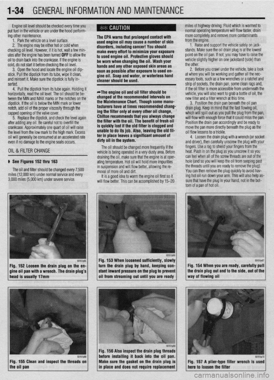
p See Figures 152 thru 153
The oil and filter should be changed every 7,500
miles (12,000 km) under normal service and every
3,000 miles (5,000 km) under severe service.
93151p-55 Fig. 152 loosen the drain plug on the en-
a wrench. The drain plug’s 3. Position the drain pan beneath the oil pan
drain plug. Keep in mind that the fast flowing oil,
which will spill out as you pull the plug from the pan,
will flow with enough force that it could miss the pan.
Position the drain pan accordingly and be ready to
move the pan more directly beneath the plug as the
oil flow lessens to a trickle.
4. Loosen the drain ~lua with a wrench (or socket
and driver), then carefuliy unscrew the plug with your
fingers. Use a rag to shield your fingers from the
heat. Push in on the plug as you unscrew it so you
draining the oil, make sure that the engine is at oper- can feel when all of the screw threads are out of the
ating temperature. Hot oil will hold more impurities hole (and so you will keep the oil from seeping past
in suspension and will flow better, allowing the re- the threads until you are ready to remove the plug).
moval of more oil and dirt. You can then remove the plug quickly to avoid hav-
It is a good idea to warm the engine oil first so it ing hot oil run down your arm. This will also help as-
will flow better. This can be accomolished bv 15-20 sure that have the plug in your hand, not in the bot-
tom of a pan of hot oil.
Fig. 153 When loosened sufficiently, slowly
turn the drain plug by hand, keeping con- Fig. 154 When you are ready, carefully pull
Fig. 156 Also inspect the drain plug th
before installing it back into the oil
Fig. 155 Clean and inspect the threads on
the oil pan Make sure the gasket on the drain plug is
in place and does not require replacement Fig. 157 A plier-type filter wrench Is used
here to loosen the filter
Page 34 of 408
GENERALINFORMATIONAND MAINTENANCE l-35
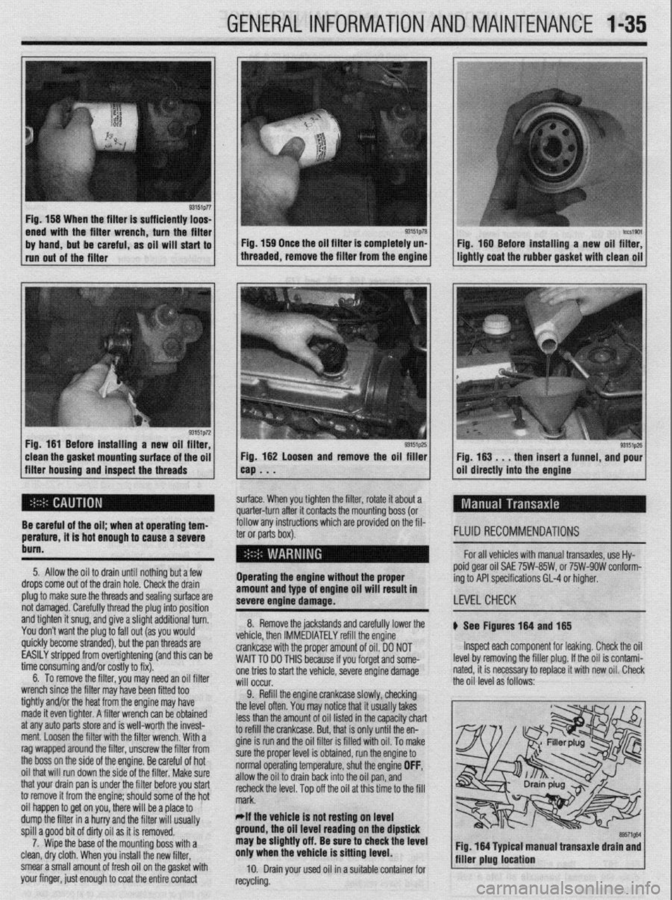
Fig. 158 When the filter is sufficiently loos-
Fig. 181 Before installing a new oil filter,
clean the gasket mounting surface of the oil
filter housing and inspect the threads Fig. 182 Loosen and remove the oil filler
cap . . .
surface. When you tighten the filter, rotate it about a
quarter-turn after it contacts the mounting boss (or Fig. 183 . , , then insert a funnel, and pour
oil directly into the engine
follow any instructions
which are provided on the fil-
ter or parts box).
Operating the engine without the proper
amount and type of engine oil will result In
severe engtne damage. FLUID RECOMMENDATIONS
For all vehicles with manual transaxles, use Hy-
poid gear oil SAE 75W-85W, or 75W-9OW conform-
ing to API specifications GL-4 or higher.
LEVELCHECK Be careful of the oil; when at operating tem-
perature, it is hot enough to cause a severe
bum.
5. Allow the oil to drain until nothing but a few
drops come out of the drain hole. Check the drain
plug to make sure the threads and sealing surface are
not damaged. Carefully thread the plug into position
and tighten it snug, and give a slight additional turn.
You don’t want the plug to fall out (as you would
quickly become stranded), but the pan threads are
EASILY stripped from overtightening (and this can be
time consuming and/or costly to fix).
6. To remove the filter, you may need an oil filter
wrench since the filter may have been fitted too
tightly and/or the heat from the engine may have
made it even tighter. A filter wrench can be obtained
at any auto parts store and is well-worth the invest-
ment. Loosen the filter with the filter wrench. With a
rag wrapped around the filter, unscrew the filter from
the boss on the side of the engine. Be careful of hot
oil that will run down the side of the filter. Make sure
that your drain pan is under the filter before you start
to remove it from the engine; should some of the hot
oil happen to get on you, there will be a place to
dump the filter in a hurry and the filter will usually
spill a good bit of dirty oil as it is removed.
7. Wipe the base of the mounting boss with a
clean, dry cloth. When you install the new filter,
smear a small amount of fresh oil on the gasket with
your finger, just enough to coat the entire contact 8. Remove the jackstands and carefully lower the
vehicle, then IMMEDIATELY refill the engine
crankcase with the proper amount of oil. DO NOT
WAIT TO DO THIS because if you forget and some-
one tries to start the vehicle, severe engine damage
will occur.
9. Refill the engine crankcase slowly, checking
the level oflen, you may r..‘:-- U.-1 :L ..-..” II.. .-L-e
lVL,VY II,UL II UUUU,,J ,“,\U.J
less than the amount of oil listed in the capacity chart
to refill the crankcase. But, that is only until the en-
gine is run and the oil filter is filled with oil. To make
sure the proper level is obtained, run the engine to
normal operating temperature, shut the engine OFF,
allow the oil to drain back into the oil pan, and
recheck the level. Top off the oil at this time to the fill
mark.
*If the vehicle Is not resting on level
ground, the oil level reading on the dipstick
may be slightly off. Be sure to check the level
only when the vehicle is sitting level.
10. Drain your used oil in a suitable container for
recycling. b See Flgures 184 and 185
Inspect each component for leaking. Check the oil
level by removing the filler plug. If the oil is contami-
nated, it is necessary to replace it with new oil. Check
the oil level as follows:
89571gM Fig. 164 Typtcal manual transaxle drain and
filler plug location
Page 42 of 408
GENERALINFORMATIONAND MAINTENANCE l-43
l Special car washing detergent is the best to
use. Liquid dishwashing detergent can remove wax
and leave the car’s paint unprotected and in addition
some liquid detergents contains abrasives which can
scratch the paint.
l Bird droppings should be removed from the
paintwork as soon as possible, otherwise the finish
may be permanently stained.
When the car is driven immediately after be-
ing washed, apply the brakes several times
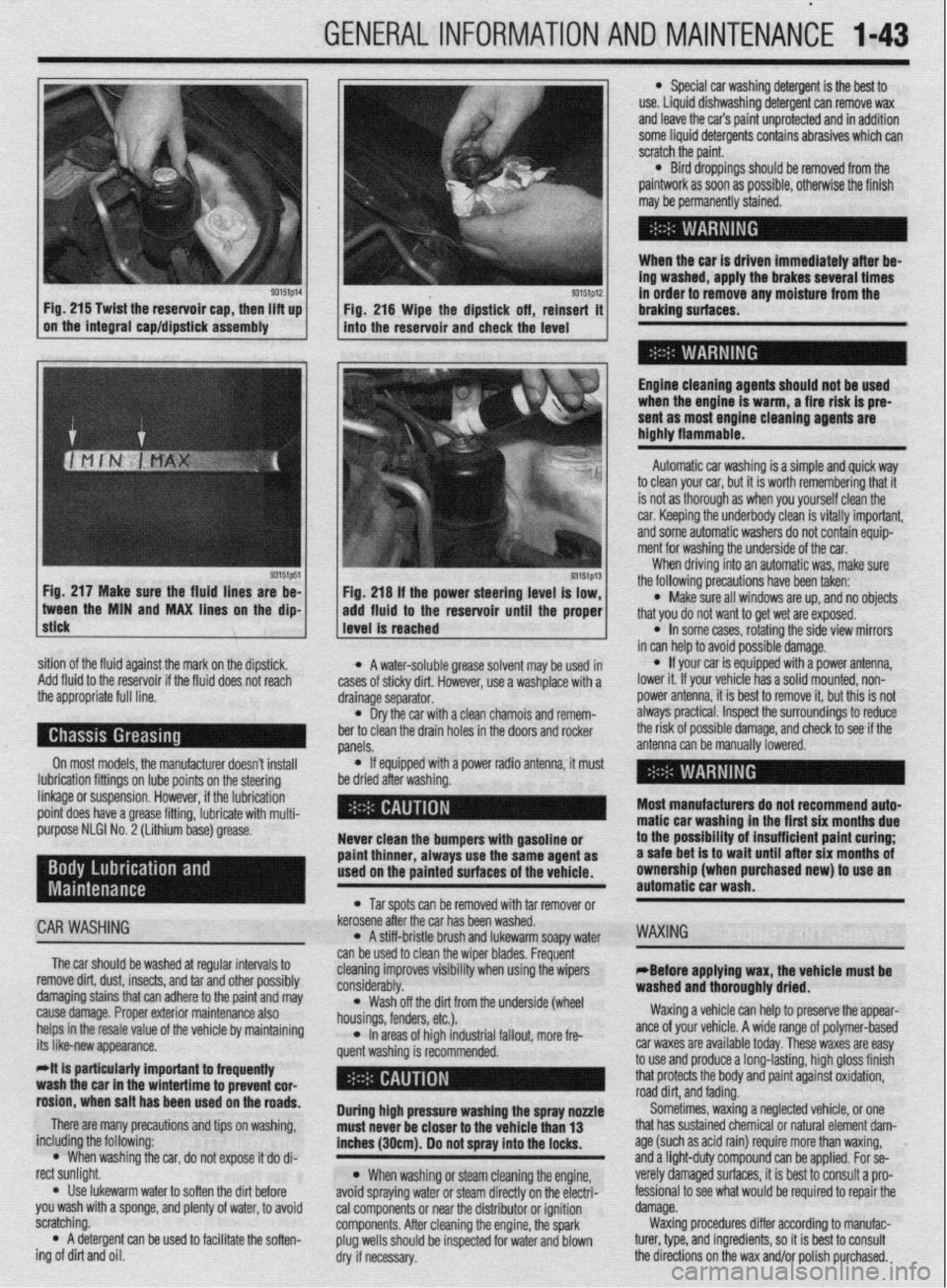
93151p14 93151p12 Fig. 215 Twist the reservoir cap, then lift up
I I
in order to remove any moisture from the
Fig. 216 Wipe the dipstick off, reinsert it braking surfaces.
on the integral cap/dipstick assembly
into the reservoir and check the level
I
Engine cleaning agents should not be used
when the engine is warm, a fire risk is pre-
sent as most engine cleaning agents are
highly flammable.
sition of the fluid against the mark on the dipstick,
Add fluid to the reservoir if the fluid does not reach
the appropriate full line.
On most models, the manufacturer doesn’t install
lubrication fittings on lube points on the steering
linkage or suspension. However, if the lubrication
point does have a grease fitting, lubricate with multi-
purpose NLGI No. 2 (Lithium base) grease.
CAR WASHING
The car should be washed at regular intervals to
remove dirt, dust, insects, and tar and other possibly
damaging stains that can adhere to the paint and may
cause damage. Proper exterior maintenance also
helps in the resale value of the vehicle by maintaining
its like-new appearance.
Mt is particularly important ta frequentiy
wash the car in the wintertime to prevent cor-
rosion, when salt has been used on the roads.
There are many precautions and tips on washing,
including the following:
l When washing the car, do not expose it do di-
rect sunlight.
. Use lukewarm water to soften the dirt before
you wash with a sponge, and plenty of water, to avoid
scratching.
l A detergent can be used to facilitate the soften-
ing of dirt and oil. * A water-soluble grease solvent may be used in
cases of sticky dirt. However, use a washplace with a
drainage separator.
l Dry the car with a clean chamois and remem-
ber to clean the drain holes in the doors and rocker
panels.
l If equipped with a power radio antenna, it must
be dried after washing.
Never clean the bumpers with gasoline or
paint thinner, always use the same agent as
used on the painted surfaces of the vehicle.
l Tar spots can be removed with tar remover or
kerosene after the car has been washed.
l A stiff-bristle brush and lukewarm soapy water
can be used to clean the wiper blades. Frequent
cleaning improves visibility when using the wipers
considerably.
l Wash off the did from the underside (wheel
housings, fenders, etc.).
l In areas of high industrial fallout, more fre-
quent washing is recommended.
During high pressure washing the spray nonle
must never be closer to the vehicle than 13
inches (30cm). Do not spray into the locks.
l When washing or steam cleaning the engine,
avoid spraying water or steam directly on the electri-
cal components or near the distributor or ignition
components. After cleaning the engine, the spark
plug wells should be inspected for water and blown
dry if necessary. Automatic car washing is a simple and quick way
to clean your car, but it is worth remembering that it
is not as thorough as when you yourself clean the
car. Keeping the underbody clean is vitally important,
and some automatic washers do not contain equip-
ment for washing the underside of the car.
When driving into an automatic was, make sure
the following precautions have been taken:
l Make sure all windows are up, and no objects
that you do not want to get wet are exposed.
l In some cases, rotating the side view mirrors
in can help to avoid possible damage.
l If your car is equipped with a power antenna,
lower it. If your vehicle has a solid mounted, non-
power antenna, it is best to remove it, but this is not
always practical. Inspect the surroundings to reduce
the risk of possible damage, and check to see if the
antenna can be manually lowered.
Most manufacturers do not recommend auto-
matic car washing in the first six months due
to the possibility of insufficient paint curing;
a safe bet is to wait until after six months of
ownership (when purchased new) to use an
automatic car wash.
WAXING
eBefore applying wax, the vehicle must be
washed and thoroughly dried.
Waxing a vehicle can help to preserve the appear-
ante of your vehicle. A wide range of polymer-based
car waxes are available today. These waxes are easy
to use and produce a long-lasting, high gloss finish
that protects the body and paint against oxidation,
road dirt, and fading.
Sometimes, waxing a neglected vehicle, or one
that has sustained chemical or natural element dam-
age (such as acid rain) require more than waxing,
and a light-duty compound can be applied. For se-
verely damaged surfaces, it is best to consult a pro-
fessional to see what would be required to repair the
damage.
Waxing procedures differ according to manufac-
turer, type, and ingredients, so it is best to consult
the directions on the wax and/or polish purchased.
Page 43 of 408
1-44 GENERALINFORMATIONAND MAINTENANCE
INTERIOR CLEANING
Upholstery
Fabric can usually be cleaned with soapy water or
a proper detergent. For more difficult spots caused by
oil, ice cream, soda, etc., use a fabric cleaner avail-
able at most parts stores. Be sure when purchasing
the cleaner to read the label to ensure it is safe to use
on your type of fabric. A safe method of testing the
cleaner is to apply a small amount to an area usually
unseen, such as under a seat, or other areas. Wart a
while, perhaps even a day to check the spot for fad-
ing, discoloring, etc., as some cleaners will only
cause these problems after they have dried
Leather upholstery requrres special care, it can be
cleaned with a mild soap and a soft cloth. It is recom-
mended that a special leather cleaner be used to
clean but also treat the leather surfaces in your vehi-
cle. Leather surfaces can age quickly and can crack if
not properly taken care of, so it is vital that the leather
surfaces be maintained.
Floor Mats and Carpet
The floor mats and carpet should be vacuumed or
brushed regularly. They can be cleaned with a mild
soap and water. Special cleaners are available to
clean the carpeted surfaces of your vehicle, but take
care in choosing them, and again it is best to test
them in a usually unseen spot.
Dashboard, Console, Door Panels, Etc.
The dashboard, console, door panels, and other
plastic, vinyl, or wood surfaces can be cleaned using
a mild soap and water. Caution must be taken to keep
water out of electronic accessories and controls to
avoid shorts or ruining the components Again spe-
cial cleaners are available to clean these surfaces, as
with other cleaners care must taken in purchasmg
and using such cleaners.
There are protectants available which can treat the
various surfaces in your car giving them a “shiny new
look”, however some of these protectants can cause
more harm than good in the long run. The shine that
is placed on your dashboard attracts sunlight accel-
erating the aging, fading and possibly even cracking
the surfaces. These protectants also attract more dust
to stick to the surfaces they treat, Increasing the cleaning you must do to maintain the appearance of
your vehicle. Personal discretion is advised here.
On most models covered by this manual, the
wheel bearmgs used are sealed units and do not re-
quire routine maintenance. However on some Galant
and Mirage models, the rear wheel bearing do require
periodic repacking. For removal and installation in-
structions, please refer to Section 7 (for rear bear-
ings) or Section 8 (for front bearings).
REPACKING
*Sodium based grease is not compatible
with lithium based grease. Read the package
labels and be careful not to mix the two
types. If there is any doubt as to the type of
grease used, completely clean the old
grease from the bearing and hub before re-
placing.
Before handling the bearings, there are a few
things that you should remember to do and not to do.
DO the following: l Remove all outside dirt from the housing be-
fore exposing the bearing.
l Treat a used bearing as gently as you would a
new one.
l Work with clean tools in clean surroundings. l Use clean, dry gloves, or at least clean, dry
hands.
l Clean solvents and flushing fluids are a must. l Use clean paper when laying out the bearings
to dry.
l Protect drsassembled bearings from rust and
dirt. Cover them up.
l Use clean, lint-free rags to wipe the bearings. l Keep the bearings in oil-proof paper when they
are to be stored or are not in use.
l Clean the inside of the housing before replac-
ing the bearin
Do NOT do he followino: El, l Do not work in dirty sirroundings. l Do not use dirty, chipped or damaged tools. l Do not work on wooden work benches or use
wooden mallets.
l Do not handle bearings with dirty or moist
hands.
l Do not use gasoline for cleaning. Use a safe
solvent.
l Do not spin dry bearings with compressed air.
They will be damaged.
l Do not use cotton waste or dirty cloths to wipe
bearings.
l Do not scratch or nick bearing surfaces. l Do not allow the bearina to come in contact
” with dirt or rust at any time.
The rear wheel bearinas on some Galant and Mi-
rage models require periodic maintenance. A pre-
mium high melting point grease meeting Grade
Multipurpose Grease NLGI Grade #2 or equivalent
must be used. Long fiber type greases must not be
used. This service is recommended every 30,000
miles (48,000 km).
*For information on Wheel Bearing removal
and installation, refer to Section 7 of this
manual.
1. Remove the wheel bearing.
2. Clean all parts in a non-flammable solvent and
let them air dry.
*Only use lint-free rags to dry the bearings.
Never spin-dry a bearing with compressed
air, as this will damage the rollers.
3. Check for excessive wear and damage. Replace
the bearing as necessary.
*Packina wheel bearinos with arease is
best accomplished by u&g a wheel bearing
packer (available at most automotive parts
stores).
4. If a wheel bearing packer is not available, the
bearings may be packed by hand.
a. Place a “healthy’ glob of grease in the
palm of one hand.
b. Force the edge of the bearing into the
grease so that the grease fills the space between
the rollers and the bearing cage.
c. Keep rotating the bearing while continuing
to push the grease through.
d. Continue until the grease is forced out the
other side of the bearing.
5. Place the packed bearing on a clean surface
and cover it until it is time for installation.
6. Install the wheel bearing.
# See Figures 219 and 220
To prevent the bumper from deforming, these vehi-
cles cannot be towed by a wrecker using sling-type
equipment. If these vehicles require towing, use a
wheel lift or flat bed equipment. It is recommended
that the vehicle be towed from the front If a flat bed is
not available.
Manual transaxle vehicles may be towed from the
rear provided that the transaxle is in Neutral and the
driveline has not been damaged. The steering wheel
must be clamped in the straight-ahead positron with a
steering wheel clamping device designed for towing
service use.
Do not use the steering column lock to secure
the front wheel uosition for towina.
Automatic transaxle vehicles may be towed on the
front wheels at speeds not to exceed 30 mph (50
km/h) for a distance not to exceed 18 miles (30 km).
If these limits can not be met, then the front wheels
must be placed on a tow dolly.
# See Figure 221
All Wheel Drive (AWD) vehicles should only be
towed with all 4 wheels on the ground or lifted from
the road surface. This means that the vehicle is to be
towed either with flatbed equipment, with all wheels
on dollies or flat towed. Damage to the viscous cou-
pling may result if the vehicle is towed with only 2
wheels on the ground.
p See Figure 222
Whenever a vehicle is jump started, precautions
must be followed In order to prevent the possibility of
Page 45 of 408
.
I-46 GENERALINFORMATIONAND MAINTENANCE
2. Pull the jumping vehicle (with the good bat-
tery) into a position so the jumper cables can reach
the dead battery and that vehicle’s engine. Make sure
that the vehicles do NOT touch.
3. Place the transmissions/transaxles of both ve-
hicles in Neutral (MT) or P (AT), as applicable, then
firmly set their parking brakes.
*ff necessary for safety reasons, the hazard
lights on both vehicles may be operated
throughout the entire procedure without sig-
nificantiy increasing the diff icuity of jumping
the dead battery.
4. Turn all lights and accessories OFF on both
vehicles. Make sure the ignition switches on both ve-
hicles are turned to the OFF position.
5. Cover the battery cell caps with a rag, but do
not cover the terminals.
6. Make sure the terminals on both batteries are
clean and free of corrosion or proper electrical con-
nection will be impeded. If necessary, clean the bat-
tery terminals before proceeding.
7. Identify the positive (+) and negative (-) termi-
nals on both batteries.
8. Connect the first jumper cable to the positive
(t) terminal of the dead battery, then connect the
other end of that cable to the positive (t) terminal of
the booster (good) battery.
9. Connect one end of the other jumper cable to
the negative (−) terminal on the booster bat-
tery and the final cable clamp to an engine bolt head,
alternator bracket or other solid, metallic point on the
engine with the dead battery. Try to pick a ground on
the engine that is positioned away from the battery in
order to minimize the possibility of the 2 clamps
touching should one loosen during the procedure.
DO NOT connect this clamp to the negative (-) termi-
nal of the bad battery. cable on the donor battery. Disconnect the positive
cable from the donor battery and finally, disconnect
the positive cable from the formerly dead battery. Be
careful when disconnecting the cables from the posi-
tive terminals not to allow the alligator clips to touch
any metal on either vehicle or a short and sparks will
occur.
I
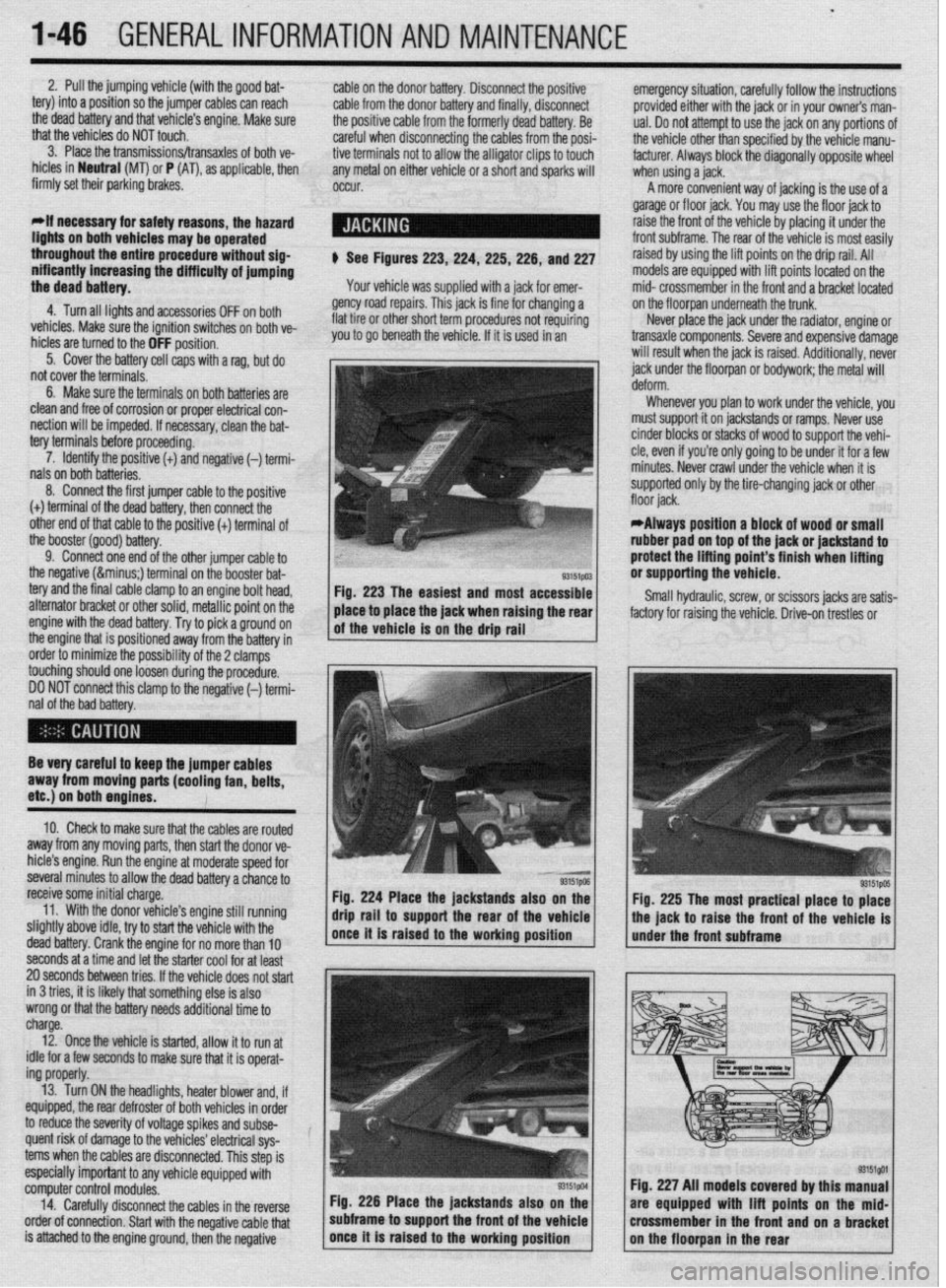
$ See Figures 223,224, 225,226, and 227
Your vehicle was supplied with a jack for emer-
gency road repairs. This jack is fine for changing a
flat tire or other short term procedures not requiring
you to go beneath the vehicle. If it is used in an emergency situation, carefully follow the instructions
provided either with the jack or in your owners man-
ual. Do not attempt to use the jack on any portions of
the vehicle other than specified by the vehicle manu-
facturer. Always block the diagonally opposite wheel
when using a jack.
A more convenient way of jacking is the use of a
garage or floor jack. You may use the floor jack to
raise the front of the vehicle by placing it under the
front subframe. The rear of the vehicle is most easily
raised by using the lift points on the drip rail. All
models are equipped with lift points located on the
mid- crossmember in the front and a bracket located
on the floorpan underneath the trunk.
Never place the jack under the radiator, engine or
transaxle components. Severe and expensive damage
will result when the jack is raised. Additionally, never
jack under the floorpan or
bodywork; the
metal will
Whenever you plan to work under the vehicle, you
must support it on jackstands or ramps. Never use
cinder blocks or stacks of wood to support the vehi-
cle, even if you’re only going to be under it for a few
minutes. Never crawl under the vehicle when it is
supported only by the tire-changing jack or other
*Always position a block of wood or small
rubber pad on top of the jack or jackstand to
protect the lifting point’s finish when lifting
or supporting the vehicle.
Small hydraulic, screw, or scissors jacks are satis-
factory for raising the vehicle. Drive-on trestles or
Be very careful to keep the jumper cables
away from moving parts (cooling fan, belts,
etc.) on both engines.
10. Check to make sure that the cables are routed
away from any moving parts, then start the donor ve-
hicle’s engine. Run the engine at moderate speed for
several minutes to allow the dead battery a chance to
receive some initial charge.
11. With the donor vehicle’s engine still running
slightly above idle, try to start the vehicle with the
dead battery. Crank the engine for no more than 10 &stands also on the
Fig. 225 The most practical place to place
front of the vehicle is
seconds at a time and let the starter cool for at least
20 seconds between tries. If the vehicle does not start
in 3 tries, it is likely thatsomething else is also
wrong or that the battery needs additional time to
charge.
12. Once the vehicle is started, allow it to run at
idle for a few seconds to make sure that it is operat-
ing properly.
13. Turn ON the headlights, heater blower and, if
equipped, the rear defroster of both vehicles in order
to reduce the severity of voltage spikes and subse-
quent risk of damage to the vehicles’ electrical sys-
tems when the cables are disconnected. This step is
especially important to any vehicle equipped with
computer control modules.
14. Carefully disconnect the cables in the’reverse
order of connection. Start with the negative cable that
is attached to the engine ground, then the negative Fig. 226 Place the jackstands also
subframe to support the front of the Fig. 227 All models covered by this
are equipped with lift points on t
crossmember in the front and on a
Page 55 of 408
.
2-8 ENGINEELECTRICAL
Front
of the
Vehicle
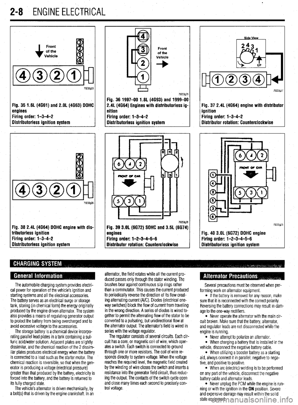
Fig. 35 1.61(4661) and 2.OL (4663) DDHC
engines
Firing order: l-3-4-2
Distributorless ignition system
Fig. 36 2.4L (4664) DDHC engine with dis-
lributorless ignition
Firing order: l-3-4-2
gistributorless ignition system
Front
of the
Vehicle
+
Fig. 36 1997-00 1.6L (4693) and 1999-00
2.41(4664) Engines with distributorless ig-
nition
Firing order: l-3-4-2
Distributorless ignition system
792!33g26 Fig. 39 3.OL (6672) SDHC and 3.5L (6674)
engines
Firing order: l-2-3-65-6
Distributor rotation: Counterclockwise Fig. 37 2.4L (4664) engine with distributor
ignition
Firing order: l-3-4-2
Distributor rotation: Counterclockwise
:ig. 40 3.OL (6672) DDHC engine
Yring order: l-2-3-4-5-6
Iistributorless ignition system
The automobile charging system provides electri-
cal power for operation of the vehicle’s ignition and
starting systems and all the electrical accessories.
The battery serves as an electrical surge or storage
tank, storing (in chemical form) the energy originally
produced by the engine driven alternator. The system
also provides a means of regulating generator output
to protect the battery from being overcharged and to
avoid excessive voltage to the accessories.
The storage battery IS a chemical device incorpo-
rating parallel lead plates in a tank containing a sul-
furic acid/water solution. Adjacent plates are slightly
dissimilar, and the chemical reaction of the 2 dissim-
ilar plates produces electrical energy when the battery
is connected to a load such as the starter motor. The
chemical reaction is reversible, so that when the gen-
erator IS producing a voltage (electrical pressure)
greater than that produced by the battery, electricity is
forced into the battery, and the battery is returned to
its fully charged state.
The vehicle’s alternator is driven mechanically, by
a belt(s) that is driven by the engine crankshaft. In an alternator, the field rotates while all the current pro-
duced passes only through the stator winding. The
brushes bear against continuous slip rings rather
than a commutator. This causes the current produced
to periodically reverse the direction of its flow creat-
ing alternating current (A/C). Diodes (electrical one-
way switches) block the flow of current from traveling
in the wrong direction. A series of diodes is wired to-
gether to permit the alternating flow of the stator to be
converted to a pulsating, but unidirectional flow at
the alternator output, The alternators field is wired in
series with the voltage regulator.
The regulator consists of several circuits. Each cir-
cuit has a core, or magnetic coil of wire, which oper-
ates a switch. Each switch is connected to ground
through one or more resistors. The coil of wire re-
sponds directly to system voltage. When the voltage
reaches the required level, the magnetic field created
by the winding of wire closes the switch and inserts a
resistance into the generator field circuit, thus reduc-
ing the output. The contacts of the switch cycle open
and close many times each second to precisely con-
trol voltage. Several precautions must be observed when per-
forming work on alternator equipment.
l If the battery is removed for any reason, make
sure that it is reconnected with the correct polarity.
Reversing the battery connections may result In dam-
age to the one-way rectifiers.
l Never operate the alternator with the main cir-
cuit broken. Make sure that the battery, alternator,
and regulator leads are not disconnected while the
engine is running.
l Never attempt to polarize an alternator. l When charging a battery that is installed in the
vehicle, disconnect the negative battery cable.
l When utilizing a booster battery as a starting
aid, always connect it in parallel; negatrve to nega-
tive, and positive to positrve.
l When arc (electric) welding is to be performed
on any part of the vehicle, disconnect the negative
battery cable and alternator leads.
l Never unplug the PCM while the engine is run-
ning or with the ignition in the ON position. Severe
and expensive damage may result within the solid
state equipment.
Page 56 of 408
ENGlNEELECTRldAL 2-9
TESTING
Voltage Test able for use by customers. An alternator
bench test is the most definitive way to de-
termine the condition of your alternator.
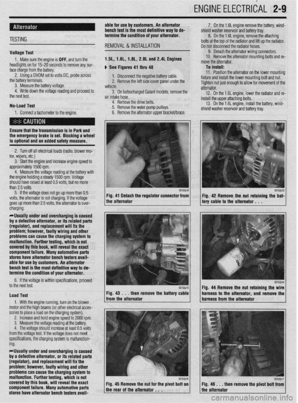
REMOVAL&INSTALLATION
1. Make sure the engine is OFF, and turn the 1.51,1.61, 1.6L, 2.OL and 2.4L Engines
headlights on for 15-20 seconds to remove any sur-
face charge from the battery. , See Figures 4, thru 48
2. Using a DVOM set to volts DC, probe across
1. Disconnect the negative battery cable.
the battery terminals.
3. Measure the battery voltage. 2. Remove the left side cover panel under the
vehicle.
4. Write down the voltage reading and proceed to
3. On turbocharaed Galant models, remove the
the next test.
air intake hose. -
No-load Test
1. Connect a tachometer to the engine. 4. Remove the drive belts.
5. Remove the water pump pulleys.
6. Remove the alternator upper bracket/brace.
Ensure that the transmission
is in Park and the emergency brake is set. Blocking a wheel
is optional and an added safety measure.
2. Turn off all electrical loads (radio, blower mo-
tor, wipers, etc.)
3. Start the engine and increase engine speed to
approximately 1500 rpm.
4. Measure the voltage reading at the battery with
the engine holding a steady 1500 rpm. Voltage
should have raised at least 0.5 volts, but no more
than 2.5 volts.
5. If the voltage does not go up more than 0.5
volts, the alternator is not charging. If the voltage
goes up more than 2.5 volts, the alternator is over-
* 7. On the 1.6L engine remove the battery, wind-
shield washer reservoir and battery tray.
8. On the 1.6L engine, remove the attaching
bolts at the top of the radiator and lift up the radiator.
Do not disconnect the radiator hoses.
9. Detach the alternator wiring connectors.
10. Remove the alternator mounting bolts and re-
move the alternator.
To install:
11. Position the alternator on the lower mountina
fixture and install the lower mounting bolt and nut. U
Tighten nut just enough to allow for movement of the
alternator.
12. On the 1.6L engine, lower the radiator and re-
install the upper attaching bolts.
13. On the 1.6L engine, install the battery, wind-
shield washer reservoir and battery tray.
/ tery cable to the alternator . , . 93152p12 Fig 42 Remove the nut retaining the bat-
cnargmg.
*Usually under and overcharging is‘caused
by a defective alternator, or its related parts
(regulator), and replacement will fix the
problem; however, faulty wiring and other
problems can
cause the charging system to
malfunction. Further testing, which is not
covered by this book, will reveal the exact
component failure. Many automotive parts
stores have alternator bench testers avaii-
able for use by customers. An alternator
bench test is the most definitive way to de-
termine the condition of your alternator.
6. If the voltage is within specifications, proceeU
to the next test.
Load Test
1. With the engine running, turn on the blower
motor and the hioh beams (or other electrical acces-
sories to place aioad on the charging system). Fig. 44 Remove the nut retaining the
then remove the batte harness to the alternator and remov
,
2. Increase and hold engine speed to 2000 rpm.
3. Measure the voltage reading at the battery.
4. The voltage should increase at least 0.5 volts
from the voltage test. If the voltage does not meet
specifications, the charging system is malfunction-
ing.
*Usually under and overcharging is caused
by a defective alternator, or its related parts
(regulator), and replacement will fix the
problem; however, faulty wiring and other
problems can cause the charging system to
malfunction. Further testing, which is not
covered by this book, will reveal the exact
component failure. Many automotive parts
stores have alternator bench testers avaii-
93152p17 en remove the pivot bolt from
Page 59 of 408
.
2-12 ENGINEELECTRICAL
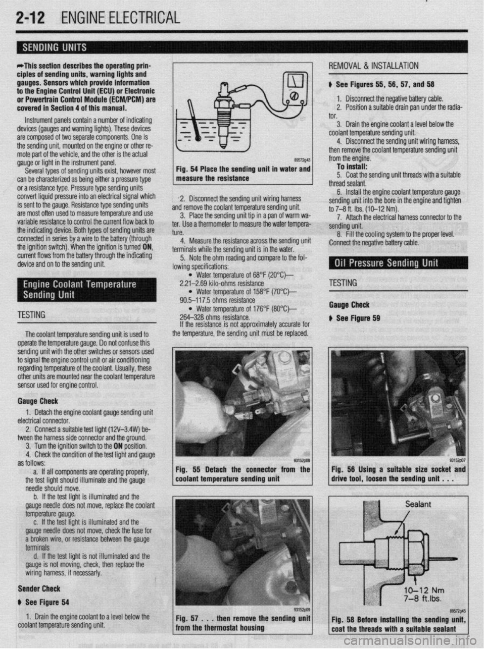
*This section describes the operating prina
ciples of sending units, warning lights and
gauges. Sensors which provide information
to the Enafne Control Unit (ECU) or Electronic
or Power&in Control Module (FCM/PCM) are
covered in Section 4 of this manual.
Instrument panels contain a number of indicating
devices (gauges and warning lights). These devices
are composed of two separate components. One is
the sending unit, mounted on the engine or other re-
mote part of the vehicle, and the other is the actual
gauge or light in the instrument panel.
Several types of sending units exist, however most
can be characterized as being either a pressure type
or a resistance type. Pressure type sending units
convert liquid pressure into an electrical signal which
is sent to the gauge. Resistance type sending units
are most often used to measure temperature and use
variable resistance to control the current flow back to
the indicatinq device. Both types of sendinq units are
connected inseries by a wimto the batteryithiough
the ignition switch). When the ignition is turned ON,
current flows from the battery through the indicating
device and on to the sending unit.
89572$43 Fig. 54 Place the sending unit in water and
measure the resistance
2. Disconnect the sending unit wiring harness
and remove the coolant temperature sending unit.
3. Place the sending unit tip in a pan of warm wa-
ter. Use a thermometer to measure the water tempera-
tl KP
L”,“.
4. Measure the resistance across the sending uni
terminals while the sending unit is in the water.
5. Note the ohm reading and compare to the fol-
lowing specifications: i, 56, 57, and 56
1. Disconnect the negative battery cable.
2. Position a suitable drain pan under the radia-
tor.
3. Drain the engine coolant a level below the
coolant temperature sending unit.
4. Disconnect the sending unit wiring harness,
then remove the coolant temperature sending unit
from the engine.
To install:
5. Coat the sending unit threads with a suitable
thread sealant.
6. Install the engine coolant temperature gauge
sending unit into the bore in the engine and tighten
to 7-8 ft. Ibs. (10-12 Nm).
7. Attach the electrical harness connector to the
sendina unit.
8. fill the cooling system to the proper level.
:onnect the negative battery cable.
l Water temperature of 68°F (2O”C)-
2.21-2.69 kilo-ohms resistance
l Water temperature of 158°F (7O’Ck
90.5-117.5 ohms resistance
TESTING l Water temperature of 176°F (8O”C)-
264-328 ohms resistance.
The coolant temperature sendina unit is used to
operate the temperature gauge. Donot confuse this
sending unit with the other switches or sensors used
to signal the engine control unit or air conditioning
regarding temperature of the coolant. Usually, these
other units are mounted near the coolant temoerature
sensor used for engine control. If the resistance is not approximately accurate for
the temperature, the sending unit must be replaced.
Gauge Check
1. Detach the engine coolant gauge sending unit
electrical connector.
2. Connect a suitable test liaht (12V-3.4W) be-
tween the harness side connector and the around.
I
3. Turn the ignition switch to the ON position.
4. Check the condition of the test light and gauge
as follows:
a. If all components are operating properly,
the test light should illuminate and the gauge
needle should move.
b. If the test light is illuminated and the
gauge needle does not move, replace the coolant
temperature gauge.
c. If the test light is illuminated and the
gauge needle does not move, check the fuse for
a broken wire, or resistance between the gauge
terminals
d. If the test light is not illuminated and the
gauge is not moving, check, then replace the
wiring harness, if necessar!y.
Sender Check
p See Figure 64
1. Drain the engine coolant to a level below the
coolant temperature sending unit Fig. 55 Detach the connector from the
coolant temperature sending unit
'ESTING
tauga Check
See Ftgure 69
Page 60 of 408
ENGINE ELECTRlCiL 2-13
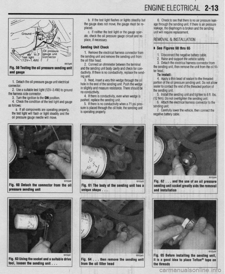
ing the oil pressure sending unit
1. Detach the oil pressure gauge unit electrical
connector.
2. Use a suitable test lioht (12V-3.4W) to around
the harnesssideconnecto~ ’ ’ -
3. Turn the ignition to the ON position.
4. Check the condition of the test light and gauge
as follows:
a. If all components are operating properly,
the test light will flash or light steadily and the
oil pressure gauge needle will move. b. If the test light flashes or lights steadily but
the gauge does not move, the gauge must be re-
placed.
c. If neither the test light or the gauge oper-
ate, check the oil pressure gauge circuit and re-
place, if necessary.
Sending Unit Check
1. Remove the electrical harness connector from
the sending unit and remove the sending unit from
the oil filter head.
2. Connect an ohmmeter between the terminal
and the sending unit body cavity and check for con-
ductivity. If there is no conductivity, replace the send-
ing unit.
3. Next, insert a very thin wedge through the oil
hole in the end of the sending unit. Push the wedge
in slightly and measure resistance. There should be
- - -- d . . . .
no conoucovey.
4. If there is conductivity, even when wedge is
pushed, replace the sending unit.
5. If there is no conductivity when a 71 psi pres-
sure is placed through the oil hole, the sending unit
is operating properly. 6. Check to see that there is no air pressure leak-
age through the sending unit. If there is air pressure
leakage, the diaphragm is broken and the sending
unit will require replacement.
REMOVAL &INSTALLATION
b See Figures 60 thru 65
1. Disconnect the negative battery cable.
2. Raise and support the vehicle safely.
3. Detach the electrical harness connector from
the sending unit, then remove the unit from the oil fil-
ter head.
To install:
4. Aoolv a thin bead of sealant to the threaded
portion of the oil pressure sending unit. Do not allow
sealer to contact the end of the threaded portion of
the sending unit.
5. Install the sending unit and tighten to 8 ft. tbs.
(12 Nm). Do not over-tighten the sending unit.
6. Attach the electrical harness connector to the
/pressure sending unit g3’9wi / m&e shape . . . Fig 60 Detach the connector from the oil
g3152w Fig 61 The body of the sending unit has a sending unit.
7. Carefully lower the vehicle, then connect the
negative battery cable.
93152PM Fig. 62 . , .
and the use of an oil pressure
sending unit socket greatly aids the removal
and installation
Fig. 65 Before installing the sending unit,
it is a good idea to place Teflon@ tape on
the threads