headlamp MITSUBISHI DIAMANTE 1900 Repair Manual
[x] Cancel search | Manufacturer: MITSUBISHI, Model Year: 1900, Model line: DIAMANTE, Model: MITSUBISHI DIAMANTE 1900Pages: 408, PDF Size: 71.03 MB
Page 57 of 408

.
2-10 ENGINEELECTRICAL 1
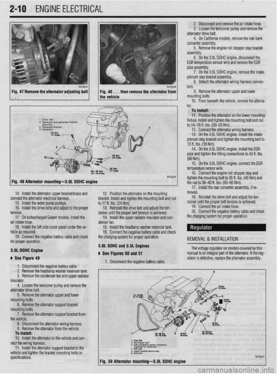
2. Disconnect and remove the air intake hose.
3. Loosen the tensioner pulley and remove the
alternator drive belt.
4. On California models, remove the rear bank
converter assembly.
5. Remove the engine roll stopper stay bracket
assembly.
6. On the 3.OL SDHC engine, disconneCt the
EGR temperature sensor wire and remove the EGR
pipe assembly.
7. On the 3.OL SOHC engine, remove the intake
plenum stay bracket assembly.
8. Detach the alternator wiring harness connec-
tors.
Fig, 47 Remove the alternator adjusting bolt
. a a 9. Remove the alternator upper and lower
mounting bolts.
10. From beneath the vehicle, remove the alterna-‘
I^”
._. To install:
11. Position the alternator on the lower mountino
fixture. Install and tighten the mounting bolt and nu<
to M-18 ft. Ibs. (20-25 Nm).
12. Connect the alternator wiring harness.
13. On the 3.OL SOHC engine, install the intake
plenum stay bracket and tighten the mounting bolt to
13 ft. Ibs. (18 Nm).
14. On the 3.OL SOHC engine, install the EGR
pipe and tighten the fitting connections to 43 ft. Ibs.
(60 Nm).
93152015
12. Position the alternator on the mour
sting hmrkd lnrtnll rmr( tinhtnn thn mm dim L VIUVI,VL. lllcllUll Ully llylllvll LltU ,,tvuln,,ly volt and nut
to 17 ft. Ibs. (24 Nm).
13. Reinstall the drive belt and adjust the ten-
pinnor fmtil the nmnor hdt toncinn ic art-:--~
15. On the 3.OL SOHC enoine. connect the EGR
- temperature sensor wire.
16. Connect the engine roll stopper stay and
tighten the mountina bolt to 35 ft. Ibs. (45 Nm) and
the nut to 36-43 ft. Tbs. (50-60 Nm).
’
17. Install the rear converter assembly, if re- Fia. 49 Alternator mountinu-3.0L DOHC enoine
14. Install the alternator upper bracket/brace and
connect the alternator electrical harness.
15. Install the water pump pulleys.
16.
Install the drive belts and adjust to the proper moved.
18. Reinstall the drive belt and adjust the ten-
sioner until the proper belt tension is achieved.
19. Connect the air intake hose.
20. Connect the neoativa hatterv rzahle and check -_. -_. __. _. _=-__
_ _-.._. , ___ _ _. _ _ _ _
the charoina system for orooer ooeration. - - _ -rr- -- - I Ull” Yvll air intake hose.
denser fan.
18.
Install the left side cover panel unde
r the ve-
15. Install the headlamp washer reservoir tank.
hid@ zx ran~kwl 1IIVI” YY ‘“~“““Y.
16. Connect the negative battery cable and check
19. Connect the negative battery cable and check
the charging svstem for proper operation.
-,-.- for proper operation. REMOVAL &INSTALLATION
3.OL SOHC n C, n---I_--
3.OL DOHC Engine
i fhs Itin** tension.
17. On turbocharged Galant models, install the
b See Figure 49
1. Disconnect the negative battery cable.
2. Remove the headlamp washer reservoir tank.
3.
Remove the condenser fan and upper radiator
insulator.
4.
Loosen the tensioner pulley and remove the
alternator drive belt. and J.DL engines
, - , lyures 50 and 51
1. Disconnect the negative battery cable. The voltage regulator on models covered by this
manual is an integral part of the alternator. If the reg-
ulator is defective, replace the alternator assembly.
5. Remove the alternator upper and lower
mounting bolts.
6. Remove the alternator support bracket
mn~lntinn h&c
_ _ _ _ -. ._ ,_._
--TT-.. -.--..-. ..-...
the vehicle.
8. Disconnect the alternator wiring harness.
Q Romnm thn slternatnr frnm thn mhirln V. llYlll”“Y LI1”“I~Y1IIU,“I II”,,, Lll” ,“,,,“,“. To install:
10.
Install the alternator to the vehicle and con-
nect the wiring harness. :z
E$llaf 3EG RtEWtiW~-~ 11
Install the alternatnr wnnnrt hrxket tn thp .._. -.. .._ - .._..._._.
--rT-.. -.--..-. .- I.._ .P _ vehicle and tighten the bracket mounting bolts to
specifications.
Page 223 of 408

.
6-20 CHASSIS ELECTRICAL
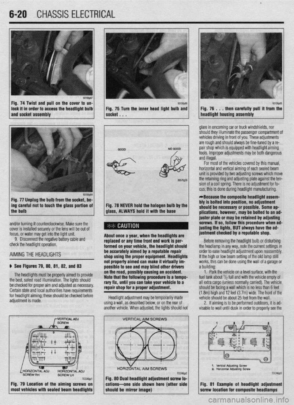
Fig. 74 Twist and pull on the cover to un-
lock it in order to access the headlight bulb
and socket assembly 93Mm Fig, 75 Turn the inner head light bulb and then carefully pull’ it from the
NO 0000 . glare in oncoming car or truck windshields, nor
should they illuminate the passenger compartment of
vehicles driving in front of you. These adjustments
are rough and should always be fine-tuned by a re-
pair shop which is equipped with headlight aiming
tools. Improper adjustments may be both dangerous
and illegal.
Fig. 77 Unplug the bulb from the socket, be-
L
ing careful not to touch the glass portion of
the bulb
I
6957Q39
Fig. 78 NEVER hold the halogen bulb by the
glass, ALWAYS hold it with the base
,
About once a year, when the headllgftts are
replaced or any time front end work is per-
formed on your vehicle, the headlight should
be accurately aimed by a reputable repair
shop uslng the proper equipment. Headlights
not properly aimed can make it virtually im-
possible to see ar Id may blind other drivers
ibly causing an accident.
Note that the’following procedure is a tempo-
rary fix, until you can take your vehicle to a
repair shop for a proper adjustment.
Headlight adjustment may be temporarily made
using a wall, as described below, or on the rear of
another vehicle. When adjusted, the lights should not For most of the vehicles covered by this manual,
horizontal and vertical aiming of eachsealed beam
unit is provided by two adjusting screws which move
the retaining ring and adjusting plate against the ten-
sion of a coil spring. There is no adjustment for fo-
cus; this is done during headlight manufacturing.
*Because the composite headlight assem-
bly is bolted into position, no adjustment
should be necessary or possible. Some ap-
plications, however, may be bolted to an ad-
juster plate or may be retained by adjusting
screws. If so, follow this procedure when ad-
@sting the lights, BUT always have the ad-
justment checked by a reputable shop.
Before removing the headlight bulb or disturbing
the headlamp in any way, note the current settings in
order to ease headlight adjustment upon reassembly.
If the high or low beam setting of the old lamp still
works, this can be done using the wall of a garage or
a building:
1. Park the vehicle on a level surface, with the
fuel tank about r/a full and with the vehicle empty of
all extra cargo (unless normally carried). The vehicle
should be facing a wall which is no less than 6 feet
(1.8m) high and 12 feet (3.7m) wide. The front of the
vehicle should be about 25 feet from the wall.
2. If aiming is to be performed outdoors, it is ad-
visable to wait until dusk in order to properly see the
% and/or turning it counterclockwise. Make sure the
cover is installed securely or the lens will be out of
focus, or water may get into the light unit.
9. Disconnect the negative battery cable and
check the headlight operation.
AIMINGTHE HEADLIGHTS
$ See Figures 79, 88, 81, 82, and 83
The headlights must be proper’ ’ ’ ’
the best, safest road illumination. ’ ’
ly armea IO provrae
The lights should
:.__1__1 __ - -___-_-. on the road, POSSI
be checked for proper aim and adfusreu as IlweSYdly. Certain state and local authorities have requirements
for headlight aiming; these should be checked before
adjustment is made.
SCFEWRH
ScFlEwLn
TCcAssa
Fig. 79 Location of the aiming screws on
most vehicles with sealed beam headlights
TCCAE@ Fig. 88 Dual headlight adjustment screw lo-
cations--one side shown here (other side
should be mirror image)
2.
TCC&z3
Fig. 81 Example of headlight adjustment
screw location for composite headlamps
Page 374 of 408

IO-6 BODYANDTRIM
1994-98 Galant .
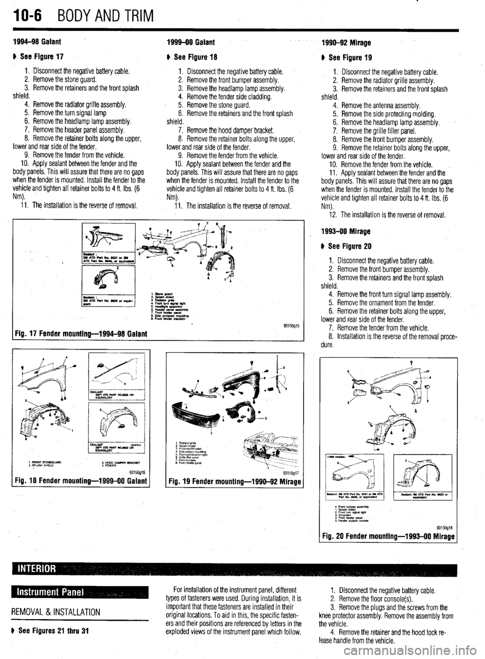
I) See Figure 17
1. Disconnect the negative battery cable.
2. Remove the stone guard. -
3. Remove the retainers and the front splash
shield.
4. Remove the radiator grille assembly.
5. Remove the turn signal lamp
6. Remove the headlamp lamp assembly.
7. Remove the header panel assembly.
8. Remove the retainer bolts along the upper,
lower and rear side of the fender.
9. Remove the fender from the vehicle.
10. Apply sealant between the fender and the
body panels, This will assure that there are no gaps
when the fender is mounted. Install the fender to the
vehicle and tighten all retainer bolts to 4 ft. Ibs. (6
Nm).
I
L
1999-00 Galant
I) See Figure 18
1. Disconnect the negative battery cable.
2. Remove the front bumper assembly.
3. Remove the headlamp lamp assembly.
4. Remove the fender side cladding.
I 5. Remove the stone guard.
6. Remove the retainers and the front splash
shield.
7. Remove the hood damper bracket.
8. Remove the retainer bolts along the upper,
lower and rear side of the fender.
9. Remove the fender from the vehicle.
10. Apply sealant between the fender and the
body panels. This will assure that there are no gaps
when the fender is mounted. Install the fender to the
vehicle and tighten all retainer bolts to 4 ft. Ibs. (6
Nm).
i 1. The installation is the reverse of removal. 11. The installation is the reverse of removal.
Fig. 17 Fender mounting-1994-98 Galant
9315Og16 Fig. 18 Fender mounting-1999-00 Galant
Fig. 19 Fender mounting-1990-92 Mirage 93150917
1990-92 Mirage
+ See Figure 19
1. Disconnect the negative battery cable.
2. Remove the radiator grille assembly.
3. Remove the retainers and the front splash
shield.
4. Remove the antenna assembly.
5. Remove the side protecting molding.
6. Remove the headlamp lamp assembly. a
7. Remove the grille filler panel.
8. Remove the front bumper assembly.
9. Remove the retainer bolts along the upper,
lower and rear side of the fender.
IO. Remove the fender from the vehicle. ~
11. Apply sealant between the fender
and the
body panels. This will assure that there are no gaps
when the fender is mounted. Install the fender to the
vehicle and tighten all retainer bolts to 4 ft. Ibs. (6
Nm).
12. The installation is the reverse of removal.
1993-00 Mirage
b See Figure 20
I. Disconnect the negative battery cable.
2. Remove the front bumper assembly.
3. Remove the retainers and the front splash
shield.
4. Remove the front turn signal lamp assembly.
5. Remove the ornament from the fender.
6. Remove the retainer bolts along the upper,
lower and rear side of the fender.
7. Remove the fender from the vehicle.
8. Installation is the reverse of the removal proce-
dure.
l Font bummer pISeWtbly 1 Splash shield
; !$yum~ slgwl l!gM 4. From lander panal
5Fenderswtlbracket 93150918 Fig. 20 Fender mounting-1993-00 Mirage
REMOVAL &INSTALLATION
6 See Figures 21 thru 31
For installation of the instrument panel, different
types of fasteners were used. During installation, it is
important that these fasteners are installed in their
original locations. To aid in this, the specific fasten-
ers and their positions are referenced by letters in the
exploded views of the instrument panel which follow. 1. Disconnect the negative battery cable.
2. Remove the floor console(s).
3. Remove the plugs and the screws from the
knee protector assembly. Remove the assembly from
the vehicle.
4. Remove the retainer and the hood lock re-
lease handle from the vehicle.
Page 395 of 408

TROUBLESHOOTING 11-13
NOTE: When one shock fails, ft is recommended to replace front or rear
units as pairs.
3. Vehicle leans excessively in turns
a. Check for worn or leaking shock absorbers or strut assemblies and replace as neces-
sary.
b. Check for missing, damaged, or worn stabilizer links or bushings, and replace or in-
stall as necessary.
4. Vehicle ride quality seems excessively ha&h
a. Check for seized shock absorbers or strut assemblies and replace as necessary.
b. Check for excessively high tire pressures and adjust pressures to vehicle recommen-
dations.
5. Vehicle seems low or leans to one side
a. Check for a damaged, broken or weak spring. Replace defective parts and check for a
needed alignment.
b. Check for seized shock absorbers or strut assemblies and replace as necessary.
c. Check for worn or leaking shock absorbers or strut assemblies and replace as neces-
sary.
Noises 1. Vehicle makes a clicking noises when driven
a. Check the noise to see if it varies with road speed. Verify if the noise is present when
coasting or with steering or throttle input. If the clicking noise frequency changes with
road speed and is not affected by steering or throttle input, check the tire treads for a
stone, piece of glass, nail or another hard object imbedded into the tire or tire tread.
Stones rarely cause a tire puncture and are easily removed. Other objects may create
an air leak when removed. Consider having these objects removed immediately at a
facility equipped to repair tire punctures.
b. If the clicking noise varies with throttle input and steering, check for a worn Constant
Velocity (CV-joint) joint, universal (U- joint) or flex joint.
2. Vehicle makes a clunking or knocking noise over bumps
a. A clunking noise over bumps is most often caused by excessive movement or clear-
ance in a suspension component. Check the suspension for soft, cracked, damaged or
worn bushings. Replace the bushings and check the vehicle’s alignment.
b. Check for loose suspension mounting bolts. Check the tightness on subframe bolts,
pivot bolts and suspension mounting bolts, and torque to specification.
c. Check the vehicle for a loose wheel bearing. Some wheel bearings can be adjusted for
looseness, while others must be replaced if loose. Adjust or replace the bearings as
recommended by the manufacturer.
d. Check the door latch adjustment. If the door is slightly loose, or the latch adjustment
is not centered, the door assembly may create noises over bumps and rough surfaces.
Properly adjust the door latches to secure the door. 3. Vehicle makes a low pitched rumbling noise when driven
a. A low pitched rumbling noise is usually caused by a drive train related bearing and is
most often associated with a wheel bearing which has been damaged or worn. The
damage can be caused by excessive brake temperatures or physical contact with a pot
hole or curb. Sometimes the noise will vary when turning. Left hand turns increase the
load on the vehicle’s right side, and right turns load the left side. A failed front wheel
bearing may also cause a slight steering wheel vibration when turning. A bearing
which exhibits noise must be replaced.
b. Check the tire condition and balance. An internally damaged tire may cause failure
symptoms similar to failed suspension parts. For diagnostic purposes, try a known
good set of tires and replace defective tires.
4. Vehicle makes a squeaking noise over bumps
a. Check the vehicle’s ball joints for wear, damaged or leaking boots. Replace a ball joint
if it is loose, the boot is damaged and leaking, or the ball joint is binding. When re-
placing suspension parts, check the vehicle for alignment.
b. Check for seized or deteriorated bushings. Replace bushings that are worn or dam-
aged and check the vehicle for alignment.
c. Check for the presence of sway bar or stabilizer bar bushings which wrap around the
bar. Inspect the condition of the bushings and replace if worn or damaged. Remove
the bushing bracket and apply a thin layer of suspension grease to the area where the
bushings wrap around the bar and reinstall the bushing brackets. ~
5. Vehicle vibrates when driven
a. Check the road surface. Roads which have rough or uneven surfaces may cause un-
usual vi brations.
b. Check the tire condition and balance. An internally damaged tire may cause failure
symptoms similar to failed suspension parts. For diagnostic purposes, try a known
good set of tires and replace defective tires immediately.
c. Check for a worn Constant Velocity (CV-joint) joint, universal (U- joint) or flex joint
and replace if loose, damaged or binding.
d. Check for a loose, bent, or out-of-balance axle or drive shaft. Replace damaged or
failed components.
NOTE: Diagnosing failures related to wheels, tires, steering and the sus-
pension system can often times be accomplished with a careful and thor-
ough test drive. Bearing noises are isolated by noting whether the noises
or symptoms vary when turning left or right, or occur while driving a
straight line. During a teft hand turn, the vehicle’s weight shifts to the
right, placing more force on the right side bearings, such that if a right side
wheel bearing is worn or damaged, the noise or vibration should increase
during light-to-heavy acceleration. Conversely, on right hand turns, the ve-
hicle tends to lean to the left, loading the left side bearings.
Knocking noises in the suspension when the vehicle is driven over rough roads, rail-
road tracks and speed bumps indicate worn suspension components such as bushings,
ball joints or tie rod ends, or a worn steering system.
1. One headlight only works on high or low beam
a. Check for battery voltage at headlight electrical connector. If battery voltage is present,
replace the headlight assembly or bulb if available separately. If battery voltage is not
present, refer to the headlight wiring diagram to troubleshoot.
2. Headlight does not work on high or low beam
a. Check for battery voltage and ground at headlight electrical connector. If battery volt-
age is present, check the headlight connector ground terminal for a proper ground. If
battery voltage and ground are present at the headlight connector, replace the head-
light assembly or bulb if available separately. If battery voltage or ground is not pre-
sent, refer to the headlight wiring diagram to troubleshoot.
b. Check the headlight switch operation. Replace the switch if the switch is defective or
ooerates intermittentlv. 1. Tail light, running light or side marker light inoperative
a. Check for battery voltage and ground at light’s electrical connector. If battery voltage is
present, check the bulb socket and electrical connector ground terminal for a proper
ground. If battery voltage and ground are present at the light connector, but not in the
socket, clean the socket and the ground terminal connector. If battery voltage and
ground are present in the bulb socket, replace the bulb. If battery voltage or ground is
not present, refer to the wiring diagram to troubleshoot for an open circuit.
b. Check the light switch operation and replace if necessary.
2. Tall light, running light or side marker light works intermittently
a. Check the bulb for a damaged filament, and replace if damaged.
b. Check the bulb and bulb socket for corrosion, and clean or replace the bulb and
socket.
w 3. Headlight(s) very dim
a. Check for battery voltage and ground at headlight electrical connector. If battery volt-
age is present, trace the ground circuit for the headlamp electrical connector, then
clean and repair as necessary. If the voltage at the headlight electrical connector is
significantly less than the voltage at the battery, refer to the headlight wiring diagram
to troubleshoot and locate the voltage drop. c. Check for loose, damaged or corroded wires and electrical terminals, and repair as
necessary.
d. Check the light switch operation and replace if necessary.
3. Tail light, running light or side marker light very dim
a. Check the bulb and bulb socket for corrosion and clean or replace the bulb and
socket.