oil change MITSUBISHI DIAMANTE 1900 User Guide
[x] Cancel search | Manufacturer: MITSUBISHI, Model Year: 1900, Model line: DIAMANTE, Model: MITSUBISHI DIAMANTE 1900Pages: 408, PDF Size: 71.03 MB
Page 87 of 408
3-26 ENGINEANDENGINEOVERHAUL
18. Remove the self-locking nuts and the small
retaining bolt holding the exhaust pipe to the bottom
of the exhaust manifold. Separate the pipe from the
manifold and remove the gasket.
19. Remove the bolts holding the support brace
to the bottom of the intake manifold.
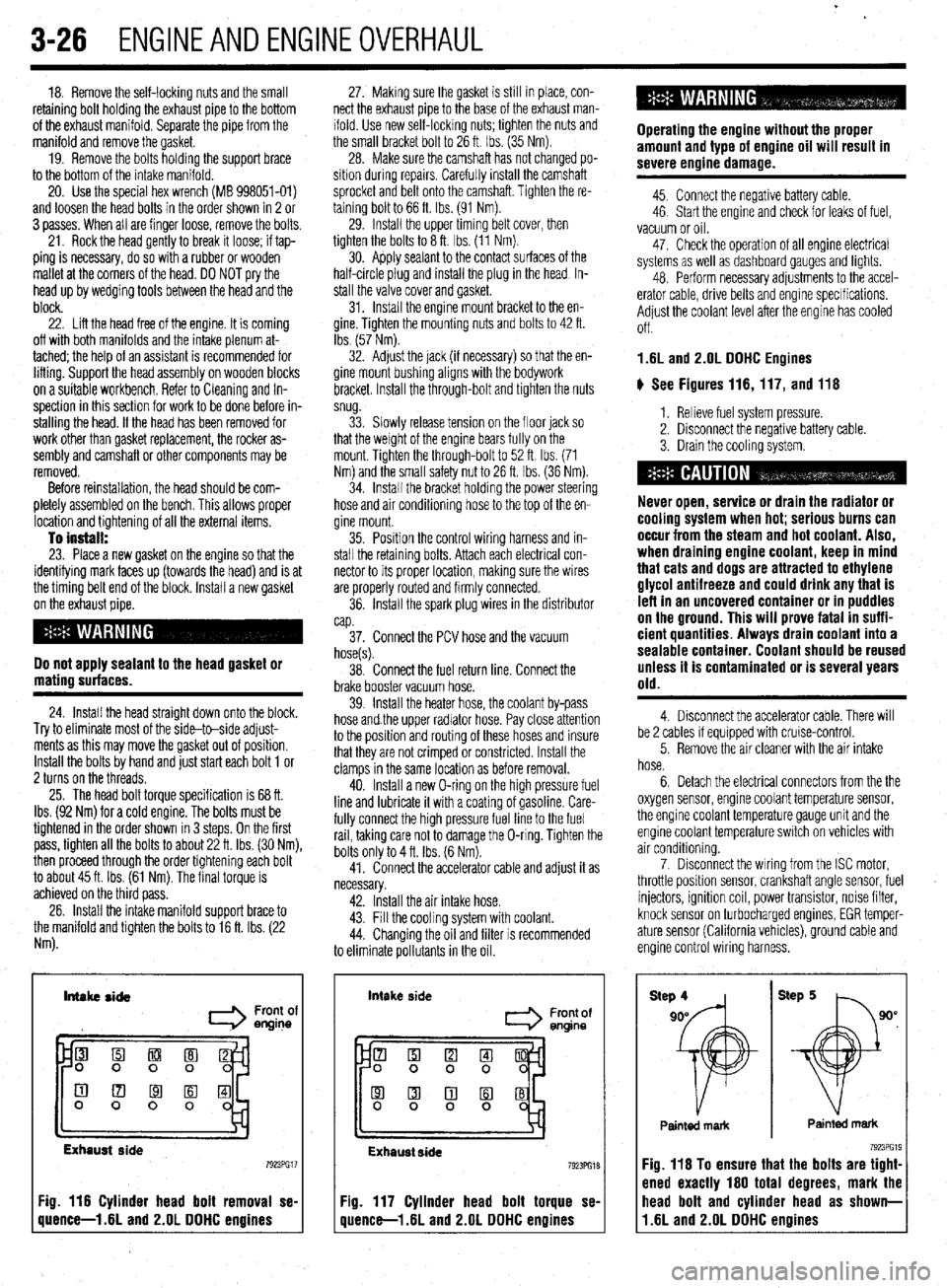
20. Use the special hex wrench (MB 998051-01)
and loosen the head bolts in the order shown in 2 or
3 passes. When all are finger loose, remove the bolts.
21. Rock the head gently to break it loose; if tap-
ping is necessary, do so with a rubber or wooden
mallet at the corners of the head. DO NOT pry the
head up by wedging tools between the head and the
block.
22. Lift the head free of the engine. It is coming
off with both manifolds and the intake plenum at-
tached; the help of an assistant is recommended for
lifting. Support the head assembly on wooden blocks
on a suitable workbench. Refer to Cleaning and In-
spection in this section for work to be done before in-
stalling the head. If the head has been removed for
work other than gasket replacement, the rocker as-
sembly and camshaft or other components may be
removed.
Before reinstallation, the head should be com-
pletely assembled on the bench. This allows proper
location and tightening of all the external items.
To install: 23. Place a new gasket on the engine so that the
identifying mark faces up (towards the head) and is at
the timing belt end of the block. Install a new gasket
on the exhaust pipe.
Do not apply sealant to the head gasket or
mating surfaces.
24. Install the head straight down onto the block.
Try to eliminate most of the side-to-side adjust-
ments as this may move the gasket out of position.
Install the bolts by hand and just start each bolt 1 or
2 turns on the threads.
25. The head bolt torque specification is 68 ft.
Ibs. (92 Nm) for a cold engine. The bolts must be
tightened in the order shown in 3 steps. On the first
pass, tighten all the bolts to about 22 ft. Ibs. (30 Nm),
then proceed through the order tightening each bolt
to about 45 ft. Ibs. (61 Nm). The final torque is
achieved on the third pass.
26. Install the intake manifold support brace to
the manifold and tighten the bolts to 16 ft. Ibs. (22
Nm). 27. Making sure the gasket is still in place, con-
nect the exhaust pipe to the base of the exhaust man-
ifold. Use new self-locking nuts; tighten the nuts and
the small bracket bolt to 26 ft. Ibs. (35 Nm).
28. Make sure the camshaft has not changed po-
sition during repalrs. Carefully install the camshaft
sprocket and belt onto the camshaft. Tighten the re-
taining bolt to 66 ft. Ibs. (91 Nm).
29. Install the upper timing belt cover, then
tighten the bolts to 8 ft. Ibs. (11 Nm).
30. Apply sealant to the contact surfaces of the
half-circle plug and install the plug in the head In-
stall the valve cover and gasket.
31. Install the engine mount bracket to the en-
gine. Tighten the mounting nuts and bolts to 42 ft.
Ibs. (57 Nm).
32. Adjust the jack (if necessary) so that the en-
gine mount bushing aligns with the bodywork
bracket. Install the through-bolt and tighten the nuts
snug.
33. Slowly release tension on the floor jack so
that the weight of the engine bears fully on the
mount. Tighten the through-bolt to 52 ft. Ibs. (71
Nm) and the small safety nut to 26 ft. tbs. (36 Nm).
34. Install the bracket holding the power steering
hose and air conditioning hose to the top of the en-
gine mount.
35. Position the control wiring harness and in-
stall the retaining bolts. Attach each electrical con-
nector to its proper location, making sure the wires
are properly routed and firmly connected.
36. Install the spark plug wires in the distributor
cap.
37. Connect the PCV hose and the vacuum
hose(s).
38. Connect the fuel return line. Connect the
brake booster vacuum hose.
39. Install the heater hose, the coolant by-pass
hose and.the upper radiator hose. Pay close attention
to the position and routing of these hoses and insure
that they are not crimped or constricted. Install the
clamps in the same location as before removal.
40. Install a new O-ring on the high pressure fuel
line and lubricate it with a coating of gasoline. Care-
fully connect the high pressure fuel line to the fuel
rail, taking care not to damage the O-ring. Tighten the
bolts only to 4 ft. Ibs. (6 Nm).
41. Connect the accelerator cable and adjust it as
necessary.
42. Install the air intake hose.
43. Fill the cooling system with coolant.
44. Changing the oil and filter is recommended
to eliminate pollutants in the oil.
Intake side
I Front of
engine
Exhaust side
Fig. 116 Cylinder head bolt removal se-
quence-l .6L and 2.OL DDHC engines intake
side
Front of
entine
Exhaust side 7923PG18
Fig. 117 Cylinder head bolt torque se-
quence-l .6L and 2.OL DDHC engines Operating the engine without the proper
amount and type of engine oil will result in
severe engine damage.
45. Connect the negative battery cable.
46. Start the engine and check for leaks of fuel,
vacuum or oil.
47. Check the operation of all engine electrical
systems as well as dashboard gauges and lights.
48. Perform necessary adjustments to the accel-
erator cable, drive belts and engine specifications.
Adjust the coolant level after the engine has cooled
Off.
1.6L and 2.OL DDHC Engines
ti See Figures 116,117, and 116
1. Relieve fuel system pressure.
2. Disconnect the negative battery cable.
3. Drain the cooling system.
Never open, service or drain the radiator or
cooling system when hot; serious burns can
occur from the steam and hot coolant. Also,
when draining engine coolant, keep in mind
that cats and dogs are attracted to ethylene
glycol antifreeze and could drink any that is
left in an uncovered container or in puddles
on the ground. This will prove fatal in suffi-
cient quantities. Always drain coolant into a
sealable container. Coolant should be reused
unless it is contaminated or is several years
old.
4. Disconnect the accelerator cable. There will
be 2 cables if equipped with cruise-control.
5. Remove the air cleaner with the air intake
hose.
6. Detach the electrical connectors from the the
oxygen sensor, engine coolant temperature sensor,
the engine coolant temperature gauge unit and the
engine coolant temperature switch on vehicles with
air conditioning.
7. Disconnect the wiring from the ISC motor,
throttle position sensor, crankshaft angle sensor, fuel
injectors, ignition coil, power transistor, noise filter,
knock sensor on turbocharged engines, EGR temper-
ature sensor (California vehicles), ground cable and
engine control wiring harness.
Painted mark Painted mark
Fig. 116 To ensure that the bolts are tight-
ened exactly 160 total degrees, mark the
11.6L and 2.OL DDHC engines head bolt and cylinder head as shown-
Page 88 of 408
ENGlNEANDENGlNEOVERHALiL 3-27
8. Remove the upper radiator hose and the
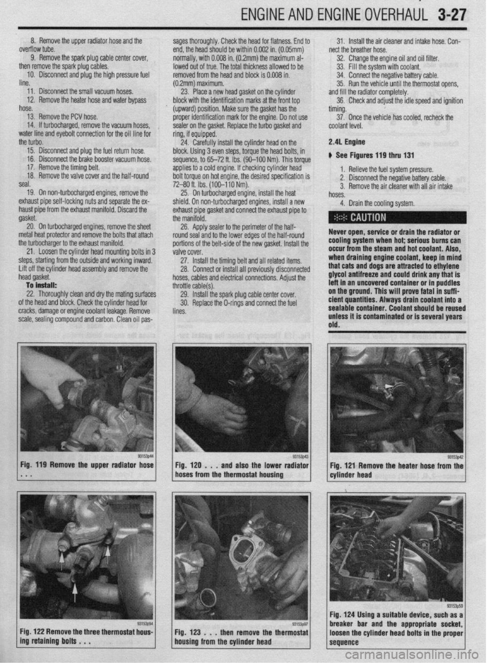
sages thoroughly. Check the head for flatness. End to 31. Install the air cleaner and intake hose. Con-
overflow tube. end, the head should be within 0.002 in. (0.05mm) nect the breather hose.
9. Remove the spark plug cable center cover,
normally, with 0.008 in. (0.2mm) the maximum al- 32. Change the engine oil and oil filter,
then remove the spark plug cables.
lowed out of true. The total thickness allowed to be 33. Fill the system with coolant.
10. Disconnect and plug the high pressure fuel
removed from the head and block is 0.008 in.
line. 34. Connect the negative battery cable.
(0.2mm) maximum. 35. Run the vehicle until the thermostat opens,
11. Disconnect the small vacuum hoses.
23. Place a new head gasket on the cylinder and fill the radiator completely.
12. Remove the heater hose and water bypass
block with the identification marks at the front top 36. Check and adjust the idle speed and ignition
hose.
(upward) position. Make sure the gasket has the timing.
13. Remove the PCV hose.
proper identification mark for the engine. Do not use 37. Once the vehicle has cooled, recheck the
14. If turbocharged, remove the vacuum hoses,
sealer on the gasket. Replace the turbo gasket and coolant level.
water line and eyebolt connection for the oil line for
ring, if equipped.
the turbo.
24. Carefully install the cylinder head on the 2.41 Engine
15. Disconnect and plug the fuel return hose. block. Using 3 even steps, torque the head bolts, in
16. Disconnect the brake booster vacuum hose.
sequence, to 65-72 ft. Ibs. (90-100 Nm). This torque b See Figures 119 thru 131
17. Remove the timing belt. applies to a cold engine. If checking cylinder head
18. Remove the valve cover and the half-round
bolt torque on hot engine, the desired specification is 1. Relieve the fuel system pressure.
seal.
7240 ft. Ibs. (100-110 Nm). 2. Disconnect the negative battery cable.
19. On non-turbocharged engines, remove the 3. Remove the air cleaner with all air intake
25. On turbocharged engine, install the heat
hoses.
exhaust pipe self-locking nuts and separate the ex-
shield. On non-turbocharged engines, install a new
haust pipe from the exhaust manifold. Discard the
exhaust pipe gasket and connect the exhaust pipe to 4. Drain the cooling system.
gasket.
the manifold.
20. On turbocharged engines, remove the sheet
26. Apply sealer to the perimeter of the half-
metal heat protector and remove the bolts that attach
round seal and to the lower edges of the half-round Never open, service or drain the radiator or
the turbocharger to the exhaust manifold.
portions of the belt-side of the new gasket. Install the cooling system when hot; serious burns can
21. Loosen the cylinder head mounting bolts in 3
valve cover. occur from the steam and hot coolant. Also,
steps, starting from the outside and working inward,
27. Install the timing belt and all related items. when draining engine coolant, keep in mind
Lift off the cylinder head assembly and remove the
28. Connect or install all previously disconnected that cats and dogs are attracted to ethylene
n head gasket.
hoses, cables and electrical connections. Adjust the glycol antifreeze and could drink any that is
To install:
throttle cable(s). left in an uncovered container or in puddles
22. Thoroughly clean and dry the mating surfaces
29. Install the spark plug cable center cover. on the ground. This will prove fatal in suffi-
of the head and block. Check the cylinder head for
30. Replace the O-rings and connect the fuel eient quantities. Always drain coolant into a
cracks, damage or engine coolant leakage. Remove
lines. sealable container. Coolant should be reused
scale, sealing compound and carbon. Clean oil pas- unless it is contaminated or is several years
old.
g3153p44 Fig. 119 Remove the upper radiator hose
* . . 1 Fig. 129 . . . and also the lower rad:gzi / cyl.der head g3153W
Fig 121 Remove the heater hose from the
hoses from the thermostat housing
Fig. 122 Remove the three thermostat hous-
Fig. 123 . . . then remove the thermostat
ing retaining bolts . . .
housing from the cylinder head
93153p50 Fig. 124 Using a suitable device, such as a
breaker bar and the appropriate socket,
loosen the cylinder head bolts in the proper
sequence
Page 90 of 408
ENGINEANDENGINEOVERHAUL 3-29
l HOzS sensor l ECT gauge sender l ECT sensor l MAP sensor l IAT sensor l TP sensor l IAC motor l injector harness l ignition coil l CMP sensor l EGR solenoid valve
33. Install the spark plug wires and cover,
34. Replace the O-rings and connect the fuel
lines.
35. Install the air cleaner and intake hose. Con-
nect the breather hose.
36. Fill the cooling system.
37. Connect the negative battery cable
3.01 DDHC Engine
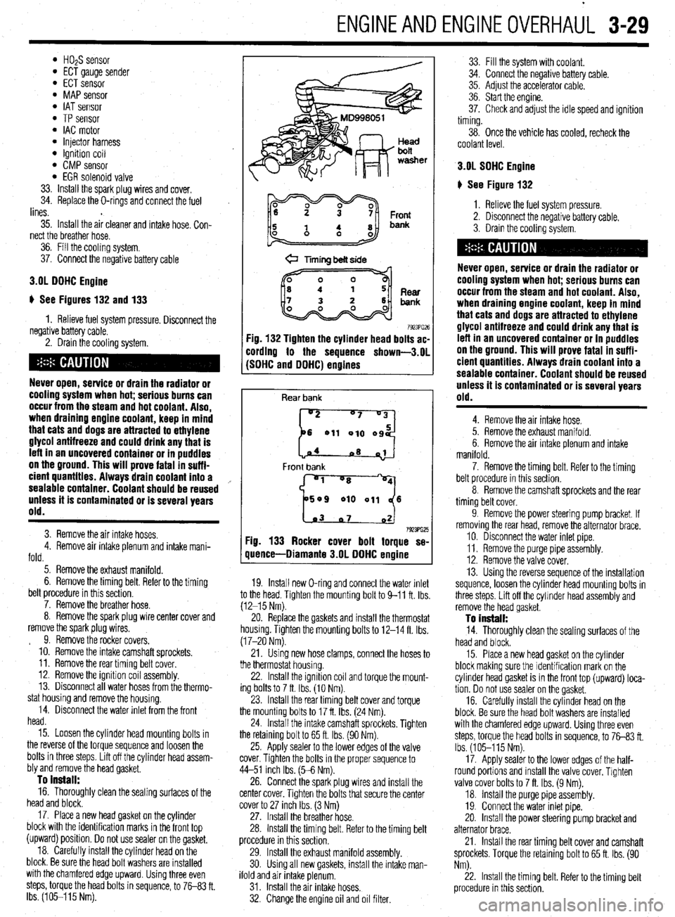
ti See Figures 132 and 133
1. Relieve fuel system pressure. Disconnect the
negative battery cable.
2. Drain the cooling system.
Never open, service or drain the radiator or
cooling system when hot; serious burns can
occur from the steam and hot coolant. Also,
when draining engine coolant, keep in mind
that cats and dogs are attracted to ethylene
glycol antifreeze and could drink any that is
left in an uncovered container or in puddles
on the ground. This will prove fatal in suffi-
cient quantltles. Always drain coolant into a
sealable container. Coolant should be reused
unless it is contaminated or is several years
old.
3. Remove the air intake hoses.
4. Remove air intake plenum and intake mani-
fold.
5. Remove the exhaust manifold.
6. Remove the timing belt. Refer to the timing
belt procedure in this section.
7. Remove the breather hose.
8. Remove the spark plug wire center cover and
remove the spark plug wires.
9. Remove the rocker covers.
10. Remove the intake camshaft sprockets.
11. Remove the rear timing belt cover.
12. Remove the ignition coil assembly.
13. Disconnect all water hoses from the thermo-
stat housing and remove the housing.
14. Disconnect the water inlet from the front
head.
15. Loosen the cylinder head mounting bolts in
the reverse of the torque sequence and loosen the
bolts in three steps. Lift off the cylinder head assem-
bly and remove the head gasket.
To install: 16. Thoroughly clean the sealing surfaces of the
head and block.
17. Place a new head gasket on the cylinder
block with the identification marks in the front top
(upward) position. Do not use sealer on the gasket,
18. Carefully install the cylinder head on the
block. Be sure the head bolt washers are installed
with the chamfered edge upward. Using three even
steps, torque the head bolts in sequence, to 76-83 ft.
Ibs. (105-115 Nm).
@ Timing belt side
7923PG26 :ig. 132 Tighten the cylinder head bolts ac-
:ording to the sequence shown-3.01
SDHC and DDHC) engines
Rear bank
[::od
04
~8 01
Front bank
'1 "8
509 010 011 6
1.03 07 02 7923ffi25 Fig. 133 Rocker cover bolt torque se-
quence-Diamante 3.OL DDHC engine
19. Install new O-ring and connect the water inlet
to the head. Tighten the mounting bolt to 9-11 ft. Ibs
(12-15 Nm).
20. Replace the gaskets and install the thermostat
housing. Tighten the mounting bolts to 12-14 ft. Ibs.
(17-20 Nm).
21. Using new hose clamps, connect the hoses to
the thermostat housing.
22. Install the Ignition coil and torque the mount-
ing bolts to 7 ft. Ibs. (10 Nm).
23. Install the rear timing belt cover and torque
the mounting bolts to 17 ft. Ibs. (24 Nm).
24. Install the intake camshaft sprockets. Tighten
the retaining bolt to 65 ft. Ibs. (90 Nm).
25. Apply sealer to the lower edges of the valve
cover. Tighten the bolts in the proper sequence to
44-51 inch Ibs. (5-6 Nm).
26. Connect the spark plug wires and install the
center cover. Tighten the bolts that secure the center
cover to 27 inch Ibs. (3 Nm)
27. Install the breather hose.
28. Install the timing belt. Refer to the timing belt
procedure in this section,
29. Install the exhaust manifold assembly.
30. Using all new gaskets, install the intake man-
ifold and air intake plenum.
31. Install the air intake hoses.
32. Change the engine oil and oil filter. 33. Fill the system wrth coolant.
34. Connect the negabve battery cable.
35. Adjust the accelerator cable.
36. Start the engine.
37. Check and adjust the idle speed and ignition
timing.
38. Once the vehicle has cooled, recheck the
coolant level.
3.OL SDHC Engine
# See Figure 132
1. Relieve the fuel system pressure.
2. Disconnect the negative battery cable.
3. Drain the cooling system.
Never open, service or drain the radiator or
cooling system when hot; serious burns can
occur from the steam and hot coolant. Also,
when draining engine coolant, keep in mind
that cats and dogs are attracted to ethylene
alvcol antifreeze and could drink any that is
Left in an uncovered container or in puddles
on the ground. This will Drove fatal in suff i-
cient quantities. Always drain coolant into a
sealable container. Coolant should be reused
Unless it is Contaminated or is several years
old.
4. Remove the air intake hose.
5. Remove the exhaust manifold.
6. Remove the air intake plenum and intake
manifold.
7. Remove the timing belt. Refer to the timing
belt procedure in this section.
8. Remove the camshaft sprockets and the rear
timing belt cover.
9. Remove the power steering pump bracket. If
removing the rear head, remove the alternator brace.
10. Disconnect the water inlet pipe.
11. Remove the purge pipe assembly.
12. Remove the valve cover,
13. Using the reverse sequence of the installation
sequence, loosen the cylinder head mounting bolts in
three steps. Lift off the cylmder head assembly and
remove the head gasket.
To install: 14. Thoroughly clean the sealing surfaces of the
head and block.
15. Place a new head gasket on the cylinder
block making sure the identification mark on the
cylrnder head gasket is in the front top (upward) loca-
tion. Do not use sealer on the gasket,
16. Carefully install the cylinder head on the
block. Be sure the head bolt washers are installed
with the chamfered edge upward. Using three even
steps, torque the head bolts in sequence, to 7683 ft.
Ibs. (105-115 Nm).
17. Apply sealer to the lower edges of the half-
round portions and install the valve cover. Tighten
valve cover bolts to 7 ft. Ibs. (9 Nm).
18. Install the purge pipe assembly.
19. Connect the water inlet pipe.
20. Install the power steering pump bracket and
alternator brace.
21. Install the rear timing belt cover and camshaft
sprockets. Torque the retaining bolt to 65 ft. Ibs. (90
Nm).
22. Install the timing belt. Refer to the timing belt
procedure in this section.
Page 118 of 408
ENGINEANDENGINEOVERHAUL 3-57
Anything that generates heat and/or friction WIII
eventually burn or wear out (for example, a light bulb
generates heat, therefore its life span is limited). With
this in mind, a running engine generates tremendous
amounts of both; friction is encountered by the mov-
ing and rotating parts inside the engine and heat is
created by friction and combustion of the fuel How-
ever, the engine has systems designed to help reduce
the effects of heat and friction and provide added
longevrty. The oiling system reduces the amount of
friction encountered by the moving parts inside the
engine, while the cooling system reduces heat cre-
ated by friction and combustion If either system is
not maintained, a break-down will be inevitable.
Therefore, you can see how regular maintenance can
affect the service life of your vehicle, If you do not
drain, flush and refill your cooling system at the
proper intervals, deposits WIII begin to accumulate in
the radiator, thereby reducing the amount of heat it
can extract from the coolant The same applies to
your oil and filter; If it is not changed often enough it
becomes laden with contaminates and is unable to
properly lubricate the engine. This increases friction
and wear.
There are a number of methods for evaluating the
condition of your engine. A compression test can re-
veal the condition of your pistons, piston rings,
cylinder bores, head gasket(s), valves and valve
seats. An oil pressure test can warn you of possible
engine bearing, or oil pump failures. Excessrve oil
consumption, evidence of oil in the engine air intake
area and/or bluish smoke from the tailpipe may indi-
cate worn piston rings, worn valve guides and/or
valve seals. As a general rule, an engine that uses no
more than one quart of oil every 1000 miles is in
good condition. Engines that use one quart of oil or
more in less than 1000 miles should first be checked
for oil leaks. If any oil leaks are present, have them
fixed before determining how much oil is consumed
by the engine, especrally if blue smoke is not visible
at the tailpipe
COMPRESSION TEST
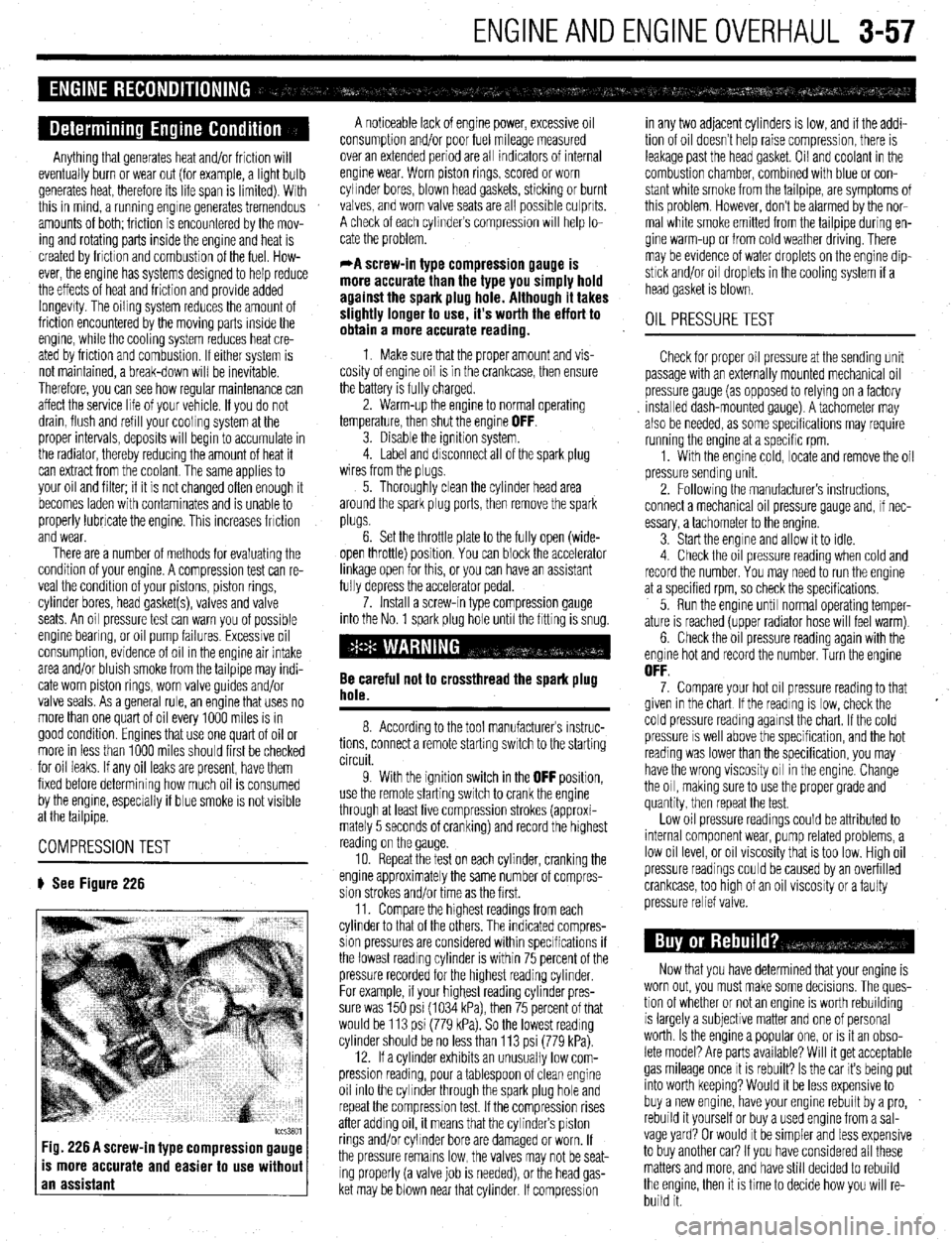
# See Figure 226
tccs3801 Fig. 226 A screw-in type compression gauge
is more accurate and easier to use without
an assistant
A noticeable lack of engine power, excessive oil
consumption and/or poor fuel mileage measured
over an extended period are all indicators of internal
engine wear. Worn piston rings, scored or worn
cylinder bores, blown head gaskets, sticking or burnt
valves, and worn valve seats are all possible culprits.
A check of each cylinders compression WIII help lo-
cate the problem.
*A screw-in type compression gauge is
more accurate than the type you simply hold
against the spark plug hole. Although it takes
slightly longer to use, it’s worth the effort to
obtain a more accurate reading.
1 Make sure that the proper amount and vis-
cosity of engine oil is in the crankcase, then ensure
the battery is fully charged.
2. Warm-up the engine to normal operating
temperature, then shut the engine
OFF. 3. Disable the ignition system.
4. Label and disconnect all of the spark plug
wires from the plugs,
5. Thoroughly clean the cylinder head area
around the spark plug ports, then remove the spark
plugs.
6. Set the throttle plate to the fully open (wide-
open throttle) position You can block the accelerator
linkage open for this, or you can have an assistant
fully depress the accelerator pedal.
7. Install a screw-in type compression gauge
into the No. 1 spark plug hole until the fitting is snug.
Be careful not to crossthread the spark plug
hole.
8. According to the tool manufacturers instruc-
tions, connect a remote starting switch to the starting
circuit.
9. With the ignition switch in the
OFF position,
use the remote starting switch to crank the engine
through at least five compression strokes (approxi-
mately 5 seconds of cranking) and record the highest
reading on the gauge
10. Repeat the test on each cylinder, cranking the
engine approximately the same number of compres-
sion strokes and/or time as the first.
11. Compare the hrghest readings from each
cylinder to that of the others. The indicated compres-
sion pressures are considered within specifications if
the lowest reading cylinder is within 75 percent of the
pressure recorded for the highest reading cylinder
For example, if your highest reading cylinder pres-
sure was 150 psi (1034 kPa), then 75 percent of that
would be 113 psi (779 kPa). So the lowest reading
cylinder should be no less than 113 psi (779 kPa).
12. If a cylinder exhibits an unusually low com-
pression reading, pour a tablespoon of clean engine
oil into the cylinder through the spark plug hole and
repeat the compression test. If the compression rises
after adding oil, it means that the cylinder’s piston
rings and/or cylinder bore are damaged or worn, If
the pressure remains low, the valves may not be seat-
ing properly (a valve job is needed), or the head gas-
ket may be blown near that cylinder. If compression in any two adjacent cylinders is low, and if the addi-
tion of oil doesn’t help raise compression, there is
leakage past the head gasket. Oil and coolant in the
combustion chamber, combined with blue or con-
stant white smoke from the tailpipe, are symptoms of
this problem. However, don’t be alarmed by the nor-
mal white smoke emitted from the tailpipe during en-
gine warm-up or from cold weather driving. There
may be evidence of water droplets on the engine dip-
stick and/or oil droplets in the cooling system if a
head gasket is blown.
OIL PRESSURETEST
Check for proper oil pressure at the sending unit
passage with an externally mounted mechanical oil
pressure gauge (as opposed to relying on a factory
Installed dash-mounted gauge). A tachometer may
also be needed, as some specifications may require
running the engine at a specific rpm.
1. With the engine cold, locate and remove the oil
pressure sending unit.
2. Followrng the manufacturers instructions,
connect a mechanical oil pressure gauge and, if nec-
essary, a tachometer to the engine.
3 Start the engine and allow it to idle.
4 Check the oil pressure reading when cold and
record the number. You may need to run the engine
at a specified rpm, so check the specifications,
5. Run the engine until normal operating temper-
ature is reached (upper radiator hose will feel warm)
6. Check the oil pressure reading again with the
engine hot and record the number. Turn the engine
OFF. 7. Compare your hot oil pressure reading to that
given in the chart If the reading is low, check the
cold pressure reading against the chart. If the cold
pressure IS well above the specification, and the hot
reading was lower than the specification, you may
have the wrong viscosity oil in the engine. Change
the oil, making sure to use the proper grade and
quantity, then repeat the test.
Low oil pressure readings could be attributed to
internal component wear, pump related problems, a
low oil level, or oil viscosity that is too low. High oil
pressure readings could be caused by an overfilled
crankcase, too htgh of an oil viscosity or a faulty
pressure relief valve.
Now that you have determined that your engine is
worn out, you must make some decisions. The ques-
tion of whether or not an engine IS worth rebuilding
is largely a subjective matter and one of personal
worth. Is the engine a popular one, or IS it an obso-
lete model? Are parts available? Will it get acceptable
gas mileage once It is rebuilt? Is the car its being put
into worth keeping? Would it be less expensive to
buy a new engine, have your engine rebuilt by a pro,
rebuild it yourself or buy a used engine from a sal-
vage yard? Or would It be simpler and less expensive
to buy another car? If you have considered all these
matters and more, and have still decided to rebuild
the engine, then it is time to decide how you will re-
build it.
Page 121 of 408
3-60 ENGINE/
-w
remove any covers remaining on the engine such as
on today’s automobiles: the Overhead Valve (OHV)
and the Overhead Camshaft (OHC). The latter can
also be broken down into two subgroups: the Single the rocker arm, front or timing cover and oil pan.
Overhead Camshaft (SOHC) and the Dual Overhead
Camshaft (DOHC). Generally, if there is only a single
camshaft on a head. it is iust referred to as an OHC Some front covers may require the vibration damper
and/or crank pulley to be removed beforehand. The
idea is to reduce the engine to the bare necessities
(cylinder head(s), valve train, engine block, crank-
shaft, pistons and connecting rods), plus any other
‘in block’ components such as oil pumps, balance
shafts and auxiliary shafts.
Finally, remove the cylinder head(s) from the en-
gine block and carefully place on a bench. Disassem-
bly instructions for each component follow later in
this section.
There are two basic types of cylinder heads used
Most cylinder heads these days are made of an
aluminum alloy due to its light weight, durability and
L--L I _--- 1^- _..^ I:,:^^ I I ^...^. .^_ ^^^I :_-_ ..^^ ,L- same environment. The same goes for any other unchanged. One aspect to pay attention to is careful
component on the cylinder head. Think of it as an in- labeling of the parts on the dual camshaft cylinder
“’ surance policy against future problems related to that head. There will be an intake camshaft and followers
component. as well as an exhaust camshaft and followers and
Unfortunately, the only way to find out which com- they must be labeled as such. In some cases, the
ponents need replacing, is to disassemble and care- components are identical and could easily be in-
fully check each piece. After the cylinder head(s) are stalled incorrectly. DO NOT MIX THEM UP! Deter-
disassembled, thoroughly clean all of the compo- mining which is which is very simple; the intake
nents. camshaft and components are on the same side of
DISASSEMBLY the head as was the intake manifold. Conversely, the
exhaust camshaft and components are on the same
side of the head as was the exhaust manifold.
ti See Figures 237 and 238
Whether it is a single or dual overhead camshaft Cup Type Camshaft Followers
cylinder head, the disassembly procedure is relatively 6 See Figures 239, 240, and 241
t “” ““’ 1 Most cylinder heads with cup type camshaft fol-
1 1 head. Also, an engine with an OHV cylinder head is j:, ’
I also known as a pushrod engine. : .; :-,
_I lowers will have the valve spring, retainer and locks
recessed within the followers bore. You will need a
C-clamp style valve spring compressor tool, an OHC
spring removal tool (or equivalent) and a small mag-
net to disassemble the head.
1. If not already removed, remove the camshaft(s)
and/or followers, Mark their positions for assembly.
2. Position the cylinder head to allow use of a C-
clamp style valve spring compressor tool.
IIRN il~llSlt?l ~Lldll~l~S. IlUWttVtJ, MS1 11011 W8S lilt: material of choice in the past, and is still used on
many vehicles today. Whether made from aluminum
or iron, all cylinder heads have valves and seats.
Some use fwo valves per cylinder, while the more hi-
tech engines will utilize a multi-valve configuration
using 3‘4 and even 5 valves per cylinder. When the
valve contacts the seat, it does so on precision ma-
chined surfaces, which seals the combustion cham-
ber, All cylinder heads have a valve guide for each
valve. The auide centers the valve to the seat and al-
lows it to move up and down within it. The clearance
between the valve and guide can be critical. Too
much clearance and the engine may consume oil,
lose vacuum and/or damaae the seat. Too little. and
the valve can stick in the guide causing the engine to
run poorly if at all, and possibly causing severe dam-
age. The last component all cylinder heads have are
valve springs. The spring holds the valve against its
seat. It also returns the valve to this position when
the valve has been opened by the valve train or
camshaft. The spring is fastened to the valve by a re-
tainer and valve locks (sometimes called keepers).
Aluminum heads will also have a valve spring shim
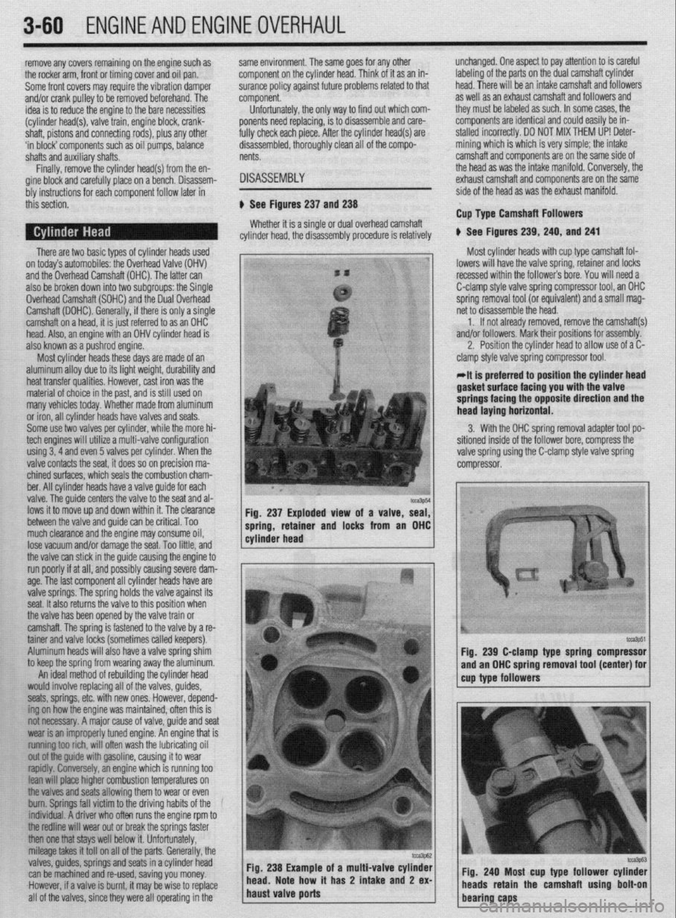
to keep the spring from wearing away the aluminum. Fig, 237 Exploded view of a valve, seal,
1 cylinder head ----r- 1 spring, retamer and locks from an OHC
An ideal method of rebuilding the cylinder head
would involve replacing all of the valves, guides,
seats, springs, etc. with new ones. However, depend-
ing on how the engine was maintained, often this is
not necessary. A major cause of valve, guide and seat
wear is an improperly tuned engine. An engine that is
~~f~t~~ rich, will often wash the lubricating oil
out ofthe guide with gasoline, causing it to wear
~~fdfy. lonely, an engine which is running too
lean wifl pface higher combustion temperatures on
Me valves and seats allowing them to wear or even
bum. Springs fall victim to the driving habits of the
f~~iduaf. A driver who often runs the engine rpm to
tfre redfine will wear out or break the springs faster
then one tfrat stays well below it. Unfortunately,
mileage takes it tot1 on all of the parts. Generally, the
valves, guides, springs and seats in a cylinder head
can be machined and re-used, saving you money.
.However, if a valve is burnt, it may be wise to replace
all of the valves, since they were all operating in the oi a multi-valve cylinder
t has 2 intake
and 2 ex-
At is preferred to position the cylinder head lasket’surtace facing you with tee valve
springs facing the opposite direction and the
lead laying horizontal.
3. With the OHC spring removal adapter tool po-
,itioned inside of the follower bore, compress the
alve spring using the C-clamp style valve spring
:ompressor.
tcca3p51 fig. 239 C-clamp type spring compressor
and an OHC spring removal tool (center) for
cup type followers
Fig. 240 Most cup type follower cylinder
/ heads retain the camshaft using bolt-on
bearing caps
Page 124 of 408
ENGINEANDENGINEOVERHAUL 3-63
Place a straightedge across the gasket surface. Valves
Using feeler gauges, determine the clearance at the
center of the straightedge and across the cylinder Any valves that were not replaced should be
head at several points. Check along the centerline refaced and the tips ground flat. Unless you have ac-
and diagonally on the head surface. If the warpage cess to a valve grinding machine, this should be
exceeds 0.003 in. (0.076mm) within a 6.0 in. done by a machine shop. If the valves are in ex-
(152cm) span, or 0.006 in. (0.152mm) over the total tremely good condition, as well as the valve seats
length of the head, the cylinder head must be resur- and guides, they may be lapped in without petform-
,
I mg macnme worK.
4
It is a recnmmended practice to lap the valves faced. After resurfacing the heads of a V-type engine
the intake manifold flange surface should be checker,
and if necessary, milled proportionally to allow for
the change in its mounting position. _ - _ _ _ .- - - _
even after machine work has been p&formed and/or
new valves have been purchased. This insures a pos-
itive seal between the valve and seat.
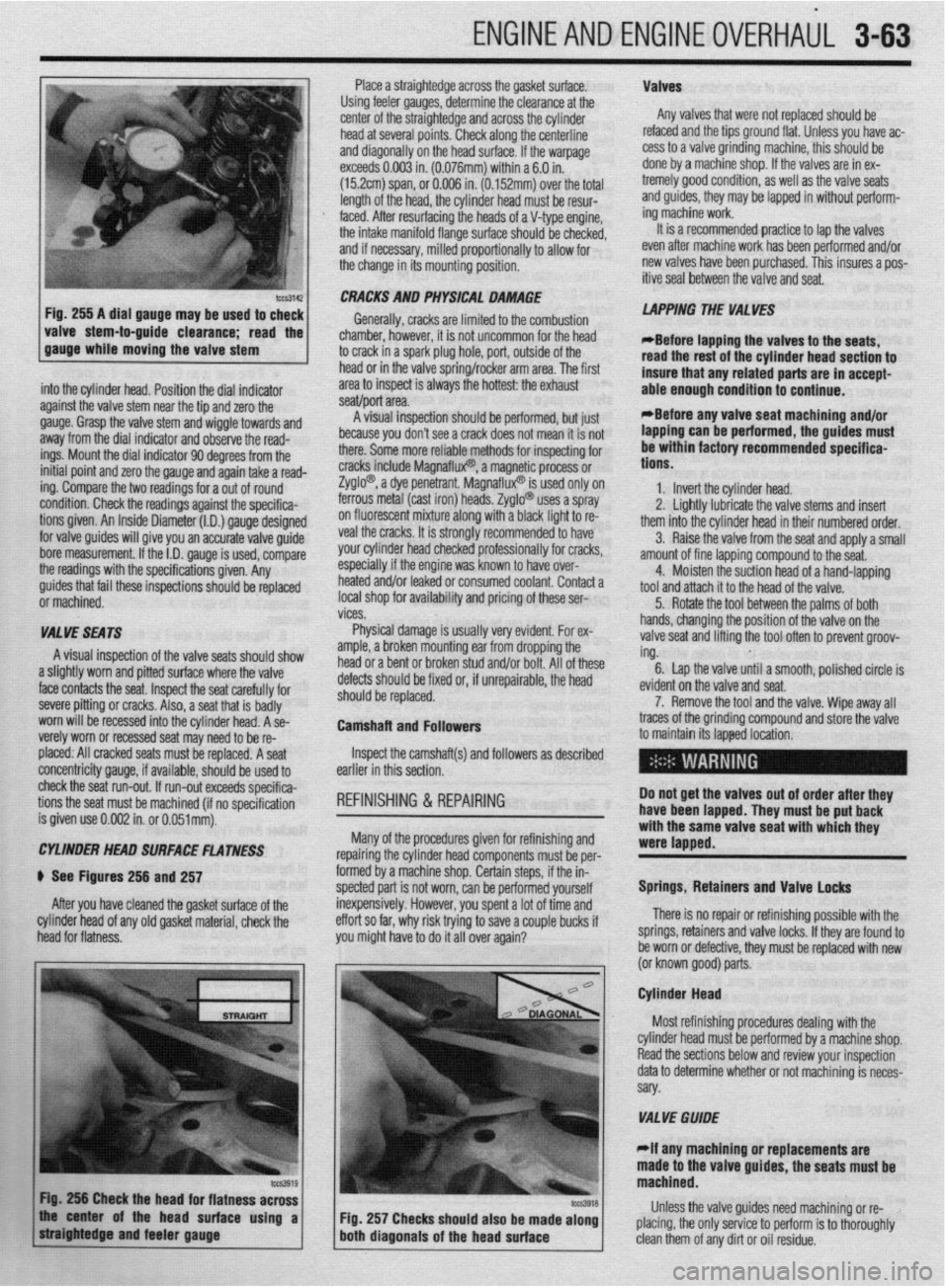
-guide clearance; the 1
read
. .
into the cylinder head. Position the dial indicator
against the valve stem near the tie and zero the
gauge. Grasp the valve stem and’wiggle towards and
away from the dial indicator and observe the read-
ings. Mount the dial indicator 90 degrees from the
initial point and zero the gauge and again take a read-
ing. Compare the two readings for a out of round
condition. Check the readings against the specifica-
tions given. An Inside Diameter (I.D.) gauge designed
for valve guides will give you an accurate valve guide
bore measurement. If the I.D. gauge is used, compare
the readings with the specifications given. Any CRACKS AND PHYSICAL DAMAGE
Generally, cracks are limited to the combustion
chamber, hbwever, it is not uncommon for the head
to crack in a spark plug hole, port, outside of the
head or in the valve spring/rocker arm area. The first
area to inspect is always the hottest: the exhaust
.I *
seawpon area.
8 I .,“““I llly”Lv”l~ .ml”“l” - plr”llll”“, ““I ,“a’
because you don’t see a crack does not mean it is not
there. Some more reliable methods for inspecting for
cracks include Magnaflux? a magn$i,c process or
Zyglo? a dye penetrant. Ma{ -’
InatluxW IS used only on
ferrous metal (cast iron) heat Is. Zyglo@ uses a spray
on fluorescent mixture along with a black light to re-
veal the cracks. It is strongly recommended to have
your cylinder head checked professionally for cracks,
especially if the engine was known to have over-
I .* I,. ..^.. LAPPING THE VALVES
*Before iaoaino the valves to the seats,
read the rest of the cylinder head section to
insure that any related parts are in accept-
able enough condition to continue.
*Before anv valve seat machining and/or
lapping can be performed, the guides must
be within factory recommended specifica-
tions.
1. Invert the cylinder head.
2. Linhtlv Iuhrir;rB the valve stems and insert
-. _ ~ . . . . . .--.._-._
them into the cylinder head in their numbered order.
3. Raise the valve from the seat and apply a small
amount of fine lanninn compound to the seat.
4.
i guides that fail these inspections should be replaced nearea analor ieaKea or consumea coolant. Contact a Moisten the suction head of a hand-lapping
tool and attach it to the head of the valve.
i or machined. local shop for availability and pricing of these ser-
5. Rotate the tool between the palms of both
I vices.
I
VALVE SEATS Physical damage is usually very evident. For ex- hands, changing the position of the valve on the
valve seat and lifting the tool often to prevent groov-
A visual inspection of the valve seats should show
amnb P hrnbn mntlntinn ear from dropping the I and/or bolt. All of these ing.
.a,... . 6. Lap the valve until a smooth, polished circle is
a slightly worn and pitted surface where the valve
face contacts the seat. Inspect the seat carefully for
severe pitting or cracks. Also, a seat that is badly
worn will be recessed into the cylinder head. A se-
verely worn or recessed seat may need to be re- uetecIs SIIOUIO oe nxea or, IT unrepairaole, me neaa
should be replaced.
Camshaft and Followers evid
7
traces of the grinding corn
to maintain its lapped loca lent on the valve and seat.
‘. Remove the tool and the valve. Wipe away all
pound and store the valve
placed: All cracked seats must be replaced. A seat
concentricity gauge, if available, should be used to
check the seat run-out. If run-out exceeds specifica-
tions the seat must be machined (if no soecification
is given use 0.002 in. or O.O51mt$. Inspect the camshaft(s) and followers as described
earlier in this section.
REFINISHING & REPAIRING Do not get the valves out of order after they
have been lapped. They must be put back
: ..^^ I... --I:^:-L!-- --A
Many of the procedures gIveI
WI WIIIIISIIIIIIJ ~IIU repairing the cylinder head components must be per-
formed by a machine shop. Certain steps, if the in-
spected part is not worn, can be performed yourself
inexpensively. However, you spent a lot of time and
effort so far, why risk trying to save a couple bucks if
you might have to do it all over again?
I- with the same valve seat with which they
were lapped.
Springs, Retainers and Valve locks
There is no repair or refinishing possible with the
springs, retainers and valve locks. If they are found to
be worn or defective, they must be replaced with new
lor known nnod narts CYLtNDEt? HEAD SURFACE FLATNESS
) See Figures 256 and 257
After you have cleaned the gasket surface of the
cylinder head of any old gasket material, check the
head for flatness.
\- - a---r r- .-.
Cylinder Head
Most refinishing procedures dealing with the
VALVE GWDE
elf any machining or replacements are
e valve guides, the seats must be
Fig. 257 Checks should also be made along Unless the valve guides need machining or re-
placing, the only service to perform is to thoroughly‘
clean them of any dirt or oil residue.
Page 130 of 408
ENGINEANDENGINEOVERHAUL 3-69
STARTING THE ENGINE
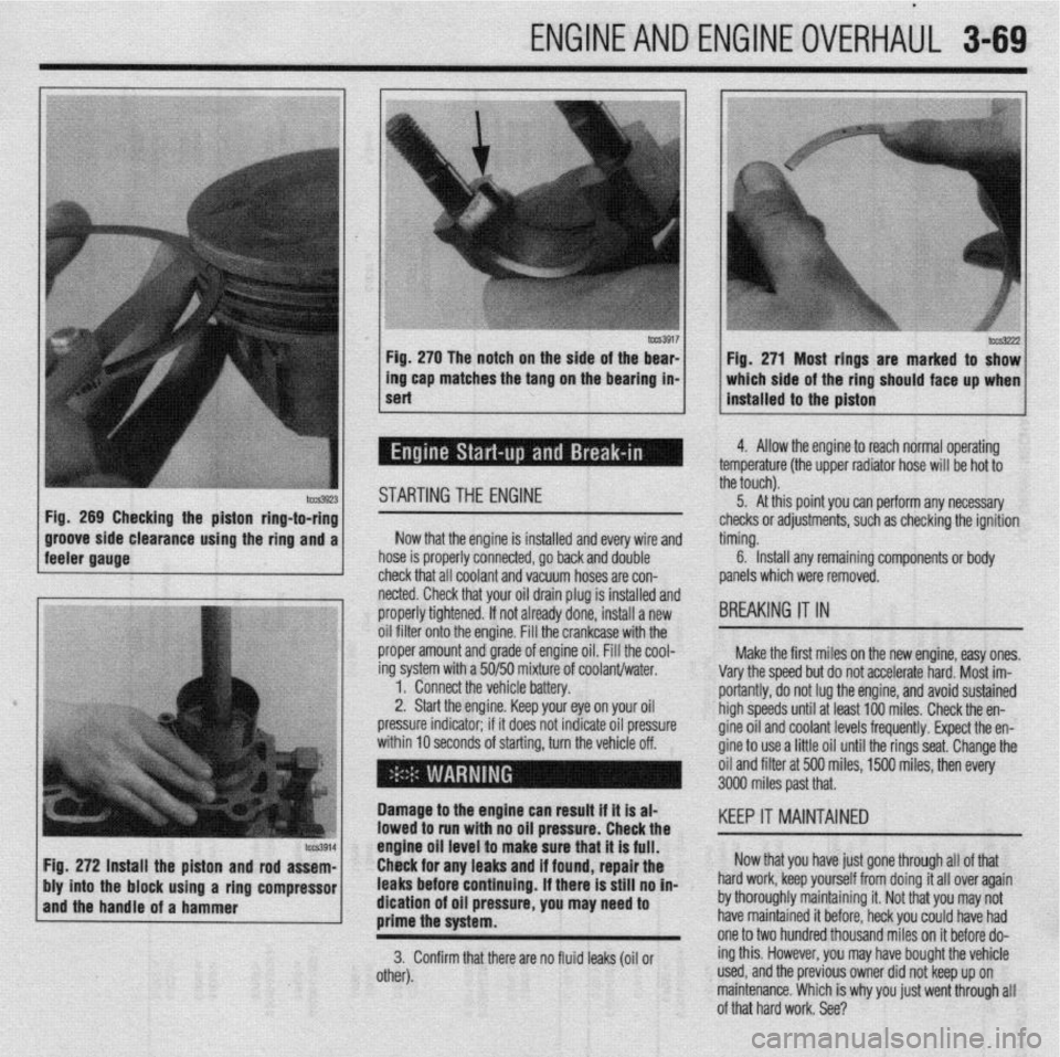
clearance using the ring and a Now that the engine is installed and every wire and
hose is properly connected, go back and double
check that all coolant and vacuum hoses are con-
, netted. Check that your oil drain plug is installed and
tt tl
C ti
hYs3222 Fig. 271 Most rings are marked to show
which side of the ring should face up when
installed to the piston
J
4. Allow the engine to reach normal operating
?mperature (the upper radiator hose will be hot to
ie touch).
5. At this point you can perform any necessary
hecks or adjustments, such as checking the ignition
ming.
6. Install any remaining components or body
anels which were removed.
IREAKING IT IN
Make the first miles on the new engine, easy ones.
arv the soeed but do not accelerate hard. Most im-
oriantly, do not lug the engine, and avoid sustained
igh speeds until at least 100 miles. Check the en-
ine oil and coolant levels frequently. Expect the en-
ine to use a little oil until the rings seat. Change the
il and filter at 500 miles, 1500 miles, then every
Page 145 of 408
4-2 DRIVEABILITYAND EMISSIONS CONTROLS
OPERATION
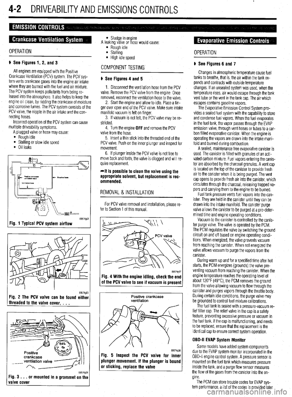
p See Figures 1, 2, and 3
All engines are equipped with the Positive
Crankcase Venhlation (PCV) system. The PCV sys-
tem vents crankcase gases into the engine air intake
where they are burned with the fuel and air mrxture.
The PCV system keeps pollutants from being re-
leased into the atmosphere It also helps to keep the
engine 011 clean, by ridding the crankcase of moisture
and corrosive fumes. The PCV system consists of the
PCV valve, the nipple in the air intake and the con-
necting hoses.
Incorrect operation of the PCV system can cause
multiple driveability symptoms.
A plugged valve or hose may cause’
l Rough Idle l Stalling or slow idle speed l Oil leaks
tT9574goi Fig. 1 Typical PCV system airflow
89574g0r5 Fig. 3 . . .
or mounted in a grommet on the
valve cover
l Sludge in en ine
A leakrng valve or ose would cause: i?
l Rough idle l Stalling l High idle speed
p See Figures 4 and 5
1. Disconnect the ventilation hose from the PCV
valve. Remove the PCV valve from the engine Once
removed, reconnect the ventilation hose to the valve.
2. Start the engine and allow to idle. Place a fin-
ger over open end of the PCV valve. Make sure intake
manifold vacuum is felt on finger.
3. If vacuum is not felt, the PCV valve may be re-
stricted.
4. Turn the engine
OFF and remove the PCV
valve from the hose.
5. Insert a thin stick into the threaded end of the
PCV valve. Push on the inner plunger and inspect for
movement.
6. If plunger inside the PCV valve is not free to
move back and forth, the valve is clogged and WIII re-
quire replacement.
*It is possible to clean the valve using the
appropriate solvent, but replacement is rec-
ommended.
REMOVAL&INSTALLATION
For PCV valve removal and installation, please re-
fer to Section 1 of this manual.
89574QO’ Fig. 4 With the engine idling, check the end
of the PCV valve to see if vacuum is present
Positive crankcase
ventilation
89574go6 Fig. 5 Inspect the PCV valve for inner
plunger movement. If the plunger is bound
or sticking, replace the valve OPERATION
p See Figures 6 and 7
Changes in atmospheric temperature cause fuel
tanks to breathe, that is, the air within the tank ex-
pands and contracts with outside temperature
changes. If an unsealed system was used, when the
temperature rises, air would escape through the tank
vent tube or the vent in the tank cap. The air which
escapes contains gasoline vapors.
The Evaporative Emission Control System pro-
vides a sealed fuel system with the capability to store
and condense fuel vapors. When the fuel evaporates
in the fuel tank, the vapor passes through the EVAP
emission valve, through vent hoses or tubes to a car-
bon filled evaporative canister. When the engine is
operahng the vapors are drawn into the intake mani-
fold and burned during combustion.
A sealed, maintenance free evaporative canister is
used The canister is filled wrth granules of an acti-
vated carbon mixture. Fuel vapors entering the canis-
ter are absorbed by the charcoal granules. A vent cap
is located on the top of the canister to provide fresh
air to the canister when it is being purged. The vent
cap opens to provide fresh air into the canister, which
circulates through the charcoal, releasing trapped va-
pors and carrying them to the engine to be burned.
Fuel tank pressure vents fuel vapors into the can-
ister. They are held in the canister until they can be
drawn into the intake manifold. The canister purge
valve allows the canister to be purged at a pre-deter-
mined time and engine operating conditions.
Vacuum to the canister is controlled by the canis-
ter purge valve. The valve IS operated by the PCM.
The PCM regulates the valve by switching the ground
circuit on and off based on engine operating condi-
tions When energized, the valve prevents vacuum
from reaching the canister. When not energized the
valve allows vacuum to purge the vapors from the
canister.
During warm up and for a specified time after hot
starts, the PCM energizes (grounds) the valve pre-
venting vacuum from reaching the canrster. When the
engine temperature reaches the operating level of
about 120°F (49°C) the PCM removes the ground
from the valve allowing vacuum to flow through the
canister and purges vapors through the throttle body.
During certain Idle conditions, the purge valve may
be grounded to control fuel mixture calibrations.
The fuel tank is sealed with a pressure-vacuum re-
lief filler cap. The relief valve in the cap is a safety
feature, preventing excessive pressure or vacuum in
the fuel tank. If the cap is malfunctioning, and needs
to be replaced, ensure that the replacement is the
identical cap to ensure correct system operation,
OBD-II EVAP System Monitor
Some models have added system components
due to the EVAP system monitor incorporated in the
OBD-II engrne control system. A pressure sensor is
mounted on the fuel tank which measures pressure
inside the tank, and a purge flow sensor measures
the flow of the gases from the canister into the en-
gine.
The PCM can store trouble codes for EVAP sys-
tem performance, a list of the codes is provided later
Page 195 of 408
5-8 FUELSYSTEM
9 ,npimr w1m.m
1: i”“L,
1: 82”w
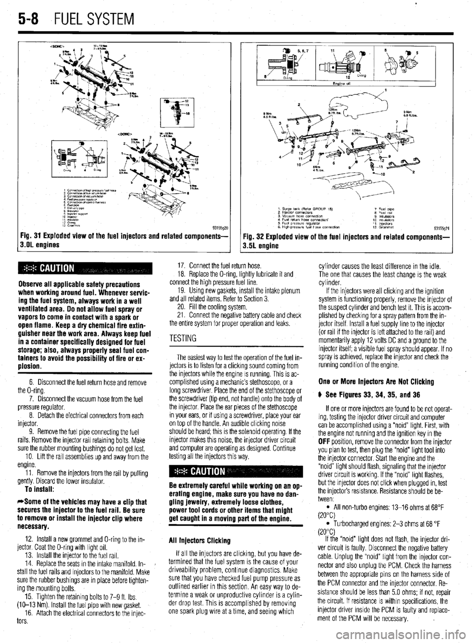
93155gx Fig. 31 Exploded view of the fuel injectors and related components-
s.OL engines
Observe all applicable safety precautions
when working around fuel. Whenever servic-
ing the fuel system, always work in a well
ventilated area. Do not allow fuel spray or
vapors to come in contact with a spark or
open flame. Keep a dry chemical fire extin-
guisher near the work area. Always keep fuel
in a container specifically designed for fuel
storage; also, always properly seal fuel con-
tainers to avoid the possibility of fire or ex-
plosion.
6. Disconnect the fuel return hose and remove
the O-ring.
7. Disconnect the vacuum hose from the fuel
pressure regulator.
8. Detach the electrical connectors from each
injector.
9. Remove the fuel pipe connectmg the fuel
rails. Remove the injector rail retaining bolts. Make
sure the rubber mounting bushings do not get lost.
10. Lift the rail assemblies up and away from the
engine.
11. Remove the injectors from the rail by pulling
gently. Discard the lower insulator.
To install:
*Some of the vehicles may have a clip that
secures the injector to the fuel rail. Be sure
to remove or install the injector clip where
necessary.
12. Install a new grommet and O-ring to the in-
jector. Coat the O-ring with light oil.
13. Install the injector to the fuel rail.
14. Replace the seats in the intake manifold. In-
stall the fuel rails and injectors to the manifold. Make
sure the rubber bushings are in place before tighten-
ing the mounting bolts.
15. Tighten the retaining bolts to 7-9 ft. Ibs.
(W-13 Nm) Install the fuel pipe with new gasket.
16. Attach the electrical connectors to the injec-
tors
Fig. 32 Exploded view of the fuel injectors and related components-
3.5L engine
17. Connect the fuel return hose.
18. Replace the O-ring, lightly lubricate it and
connect the high pressure fuel line.
19. Usmg new gaskets, install the intake plenum
and all related items. Refer to Section 3.
20. Fill the cooling system.
21. Connect the negative battery cable and check
the entire system for proper operation and leaks.
The easiest way to test the operation of the fuel in-
jectors is to listen for a clicking sound coming from
the injectors while the engine IS running. This is ac-
complished using a mechanic’s stethoscope, or a
long screwdriver. Place the end of the stethoscope or
the screwdriver (tip end, not handle) onto the body of
the injector. Place the ear pieces of the stethoscope
in your ears, or if using a screwdriver, place your ear
on top of the handle. An audible chcking noise
should be heard; this is the solenoid operating. If the
injector makes this noise, the injector driver circuit
and computer are operating as designed. Continue
testing all the injectors this way.
Be extremely careful while working on an op-
erating engine, make sure you have no dan-
gling jewelry, extremely loose clothes,
power tool cords or other items that might
get caught in a moving part of the ermine.
All Injectors Clicking
If all the injectors are clicking, but you have de-
termined that the fuel system is the cause of your
driveability problem, continue diagnostics. Make
sure that you have checked fuel pump pressure as
outlined earlier in this section. An easy way to de-
termine a weak or unproductive cylinder is a cylin-
der drop test. This is accomplished by removing
one spark plug wire at a time, and seeing which cylinder causes the least difference in the idle.
The one that causes the least change is the weak
cylinder.
If the injectors were all clicking and the ignition
system is functioning properly, remove the injector of
the suspect cylinder and bench test it. This is accom-
plished by checking for a spray pattern from the in-
jector itself Install a fuel supply line to the injector
(or rail if the injector is left attached to the rail) and
momentarily apply 12 volts DC and a ground to the
injector itself; a visible fuel spray should appear. If no
spray is achieved, replace the injector and check the
running condition of the engine.
One or More Injectors Are Not Clicking
6 See Figures 33, 34, 35, and 36
If one or more injectors are found to be not operat-
ing, testing the injector driver circuit and computer
can be accomplished using a “noid” light. First, with
the engine not running and the ignition key in the
OFF position, remove the connector from the injector
you plan to test, then plug the “noid” light tool into
the injector connector. Start the engine and the
“noid” light should flash, signaling that the injector
driver circuit is working. If the “noid” light flashes,
but the injector does not click when plugged in, test
the injectors resistance. Resistance should be be-
tween:
l All non-turbo engines: 13-16 ohms at 68°F
(20°C)
l Turbocharged engines: 2-3 ohms at 68 “F
(20°C)
If the “noid” light does not flash, the injector dri-
ver circuit is faulty. Disconnect the negative battery
cable. Unplug the “noid” light from the injector con-
nector and also unplug the PCM. Check the harness
between the appropriate pins on the harness side of
the PCM connector and the injector connector. Re-
sistance should be less than 5.0 ohms; if not, repair
the circuit. If resistance
IS within specifications, the
injector driver inside the PCM is faulty and replace-
ment of the PCM will be necessary.
Page 205 of 408
6-2 CHASSIS ELECTRICAL
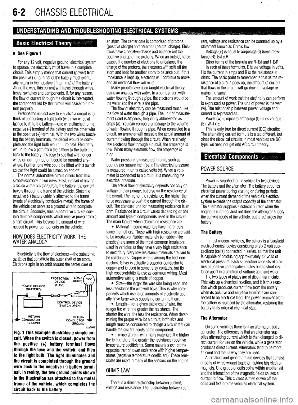
) See Figure 1
For any 12 volt, negative ground, electrical system
to operate, the electricity must travel in a complete
circurt. This simply means that current (power) from
the posibve (t) terminal of the battery must eventu-
ally return to the negative (-) terminal of the battery.
Along the way, this current will travel through wires,
fuses, switches and components. If, for any reason,
the flow of current through the circuit is interrupted,
the component fed by that circuit will cease to func-
tion properly.
Perhaps the easiest way to visualize a circuit is to
think of connecting a light bulb (with two wires at-
tached to it) to the battery-one wire attached to the
negative (-) terminal of the battery and the other wire
to the positive (t) terminal. With the two wires touch-
ing the battery terminals, the circuit would be com-
plete and the light bulb would illummate. Electricity
would follow a path from the battery to the bulb and
back to the battery. It’s easy to see that wrth longer
wires on our light bulb, it could be mounted any-
where. Further, one wire could be fitted with a switch
so that the light could be turned on and off.
The normal automotive circuit differs from this
simple example in two ways, Frrst, instead of having
a return wire from the bulb to the battery, the current
travels through the frame of the vehicle. Since the
negative (-) battery cable is attached to the frame
(made of electrically conductive metal), the frame of
the vehicle can serve as a ground wire to complete
the circuit. Secondly, most automotive circuits con-
tain multiple components which receive power from a
single circuit. This lessens the amount of wire
needed to power components on the vehicle.
HOW DOES ELECTRlClTYWORK:THE
WATER ANALOGY
Electricity is the flow of electrons-the subatomic
particles that constitute the outer shell of an atom.
Electrons spin in an orbit around the center core of
RETURN
RETURN
CONDUCTOR
CONDUCTOR
GROUND
GROUND
lccs2w
Fig. 1 This example illustrates a simple cir-
cuit. When the switch is closed, power from
the positive (t) battery terminal flows
through the fuse and the switch, and then
to the light bulb. The light illuminates and
the circuit is completed through the ground
wire back to the negative (-) battery termi-
nal. In reality, the two ground points shown
in the illustration are attached to the metal
frame of the vehicle, which completes the
circuit back to the battery
an atom The center core is comprised of protons
(positive charge) and neutrons (neutral charge). Elec-
trons have a negative charge and balance
out the
positive charge of the protons. When an outside force
causes the number of electrons to unbalance the
charge of the protons, the electrons will split off the
atom and look for another atom to balance out. If this
imbalance is kept up, electrons will continue to move
and an electrical flow will exist.
Many people have been taught electrical theory
using an analogy with water. In a comparison wrth
water flowing through a pipe, the electrons would be
the water and the wire is the pipe.
The flow of electricity can be measured much like
the flow of water through a pipe. The unit of measure-
ment used is amperes, frequently abbreviated as
amps (a). You can compare amperage to the volume
of water flowing through a pipe. When connected to a
circuit, an ammeter WIII measure the actual amount of
current flowing through the circuit. When relatively
few electrons flow through a circuit, the amperage is
low. When many electrons flow, the amperage is
high.
Water pressure is measured in units such as
pounds per square inch (psi); The electrical pressure
is measured in unrts called volts (v). When a volt-
meter is connected to a circuit, it is measuring the
electrical pressure.
The actual flow of electricity depends not only on
voltage and amperage, but also on the resistance of
the circuit The higher the resistance, the higher the
force necessary to push the current through the cir-
cuit. The standard unit for measuring resistance is an
ohm. Resistance in a crrcuit varies dependmg on the
amount and type of components used in the circuit.
The main factors which determine resistance are:
l Material-some materials have more resis-
tance than others Those with high resistance are said
to be insulators Rubber materials (or rubber-like
plashcs) are some of the most common insulators
used in vehicles as they have a very high resistance
to electricity Very low resistance materials are said to
be conductors. Copper wire is among the best con-
ductors. Silver is actually a superior conductor to
copper and is used in some relay contacts, but its
high cost prohibits its use as common wiring Most
automotive wiring is made of copper.
l Size-the larger the wire size being used, the
less resistance the wire will have. This IS why com-
ponents which use large amounts of electricity usu-
ally have large wires supplying current to them.
l Length-for a given thickness of wire, the
longer the wire, the greater the resistance. The
shorter the wire, the less the resistance. When deter-
mining the proper wire for a circuit, both size and
length must be considered to design a circuit that can
handle the current needs of the component.
l Temperature-with many materials, the higher
the temperature, the greater the resistance (positive
temperature coefficient). Some materials exhibit the
opposite trait of lower resistance with higher temper-
atures (negative temperature coefficient). These prin-
ciples are used in many of the sensors on the engine
OHM'S LAW
There is a direct relationship between current,
voltage and resistance. The relationship between cur- rent, voltage and resistance can be summed up by a
statement known as Ohm’s law.
Voltage (E) is equal to amperage (I) times resis-
tance (R): E=l x R
Other forms of the formula are R=E/I and I=E/R
In each of these formulas, E is the voltage in volts,
I is the current in amps and R IS the resistance in
ohms. The basic point to remember is that as the re-
sistance of a circuit goes up, the amount of current
that flows in the circuit will go down, if voltage re-
mains the same.
The amount of work that the electricity can perform
is expressed as power. The unit of power is the watt
(w). The relationship between power, voltage and
current
IS expressed as:
Power(w) is equal to amperage (I) times voltage
(E): W=l x E
This is only true for direct current (DC) circuits:
The alternating current formula is a tad different, but
since the electrical circuits in most vehicles are DC
type, we need not get into AC circuit theory.
POWERSOURCE
Power is supplied to the vehicle by two devices:
The battery and the alternator. The battery supplies
electrical power during starting or during periods
when the current demand of the vehicle’s electrical
system exceeds the output capacity of the alternator.
The alternator supplies electrical current when the
engine is running
Just not does the alternator supply
the current needs of the vehicle, but it recharges the
battery.
The Battery
In most modern vehicles, the battery is a lead/acid
electrochemical device consisting of six 2 volt sub-
sections (cells) connected in series, so that the unit
is capable of producing approximately 12 volts of
electrical pressure. Each subsection consists of a se-
ries of positive and negative plates held a short dis-
tance apart in a solutron of sulfuric acid and water.
The two types of plates are of dissimilar metals,
This sets up a chemrcal reaction, and it is this reac-
tion which produces current flow from the battery
when Its positive and negattve terminals are con-
nected to an electrical load. The power removed from
the battery is replaced by the alternator, restoring the
battery to its original chemical state.
The Alternator
On some vehicles there isn’t an alternator, but a
generator. The difference IS that an alternator sup-
plies alternating current which is then changed to di-
rect current for
use on the vehicle, while a generator
produces direct current. Alternators tend to be more
efficient and that is why they are used.
Alternators and generators are devices that consist
of coils of wires wound together making big electro-
magnets. One group of coils spins within another set
and the interaction of the magnetic fields causes a
current to flow. This current is then drawn off the
coils and fed into the vehicles electrical system.