wiper fluid MITSUBISHI DIAMANTE 1900 Repair Manual
[x] Cancel search | Manufacturer: MITSUBISHI, Model Year: 1900, Model line: DIAMANTE, Model: MITSUBISHI DIAMANTE 1900Pages: 408, PDF Size: 71.03 MB
Page 1 of 408
HOW TO USE THIS BOOK 1-2
WHERE TOBEGIN l-2
AVOIDINGTROUBLE 1-2
MAINTENANCEORREPAIR? 1-2
AVOIDINGTHEMOSTCOMMONMISTAKES l-2
TOOLS AND EQUIPMENT 1-2
SPECIALTOOLS l-4
YOUR VEHICLE SAFELY 1-4
DON'TS l-6
FASTENERS, MEASUREMENTS AND
CONVERSIONS l-6
BOLTS,NUTSANDOTHERTHREADED
RETAINERS 1-6
TORQUE l-7
TORQUEWRENCHES l-7
TORQUEANGLEMETERS 1-9
STANDARDANDMETRIC MEASUREMENTS l-9
SERIAL NUMBER IDENTIFICATION l-10
VEHICLE IDENTIFICATION NUMBER l-10
ENGINE IDENTIFICATION NUMBER I-10
TRANSAXLEIDENTIFICATION I-10
DRlVEAXLE(AWDGALANTONLY) l-10
TRANSFERCASE(AWDGALANTONLY) l-10
ROUTINE MAINTENANCE AND TUNE-UP l-14
AIRCLEANER(ELEMENT) 1-14
REMOVAL&INSTALLATION 1-14
FUELFILTER 1-15
REMOVAL &INSTALLATION l-15
PCVVALVE l-15
REMOVAL&INSTALLATION l-15
EVAPORATIVECANISTER l-16
SERVICING 1-16
BATTERY 1-16
PRECAUTIONS I-16
GENERALMAINTENANCE 1-16
BEL BATTERYFLUID 1-16
CABLES I-17
CHARGING I-18
REPLACEMENT 1-18
TS 1-18
INSPECTiON l-18
ADJUSTMENT 1-18
REMOVAL&INSTALLATION 1-18
TIMINGBELTS l-20
INSPECTION l-20
HOSES I-20
INSPECTION l-20
REMOVAL&INSTALLATION
CV-BOOTS 1-21
INSPECTION l-21
SPARKPLUGS l-22
SPARKPLUGHEATRANGE
REMOVAL&INSTALLATION
INSPECTION &GAPPING 1.
SPARKPLUG WIRES 1-24
TESTING 1-24
REMOVAL&INSTALLATION
DISTRIBUTORCAPANDROTOR
REMOVAL&INSTALLATION
INSPECTION 1-25
IGNITIONTIMING 1-25
. GENERALINFORAMTION l-
lNSPECTlON&ADJUSTMENl
VALVE LASH l-27
ADJUSTMENT l-27
IDLESPEED 1-28 1-21
l-22
l-22
-23
1-24
l-25
l-25
.25
1-26
AIR CONDITIONING SYSTEM 1-28
SYSTEMSERVlCEiiREPAlR l-28
PREVENTIVEMAINTENANCE 1-28
SYSTEM INSPECTION l-29
WINDSHIELD WIPERS l-29
ELEMENT(REFILL)CARE&
REPLACEMENT l-29
TIRESANDWHEELS l-30
TIRE ROTATION I-30
TIRE DESIGN 1-31
TIRESTORAGE l-31
INFLATION &INSPECTION l-31
CARE OFSPECIALWHEELS l-32 OPERATION INFOREIGNCOUNTRIES l-33
ENGINE l-33
OILLEVELCHECK 1-33
OIL& FILTER CHANGE l-34
MANUALTRANSAXLE l-35
FLUIDRECOMMENDATIONS l-35
LEVELCHECK l-35
DRAIN&REFILL l-36
AUTOMATICTRANSAXLE l-36
FLUIDRECOMMENDATIONS l-36
LEVELCHECK 1-36
DRAIN&REFILL l-36
PAN & FILTERSERVICE 1-36
TRANSFERCASE(AWDGAlANT ONLY) l-38
FLUIDRECOMMENDATIONS l-38
LEVELCHECK l-38
DRAIN&REFILL l-38
REARDRlVEAXLE(AWDGALANTONLY) l-38
FLUIDRECOMMENDATIONS l-38
LEVELCHECK l-38
DRAIN&REFILL l-38
COOLINGSYSTEM l-39
FLUIDRECOMMENDATIONS l-39
iM-41
FLUIDS AND LUBRICANTS 1-33
FLUID DISPOSAL 1-33
FlJELANDENGlNEOILRECOMMENDATlONS
ENGINE OIL l-33
FUEL l-33
Page 42 of 408
GENERALINFORMATIONAND MAINTENANCE l-43
l Special car washing detergent is the best to
use. Liquid dishwashing detergent can remove wax
and leave the car’s paint unprotected and in addition
some liquid detergents contains abrasives which can
scratch the paint.
l Bird droppings should be removed from the
paintwork as soon as possible, otherwise the finish
may be permanently stained.
When the car is driven immediately after be-
ing washed, apply the brakes several times
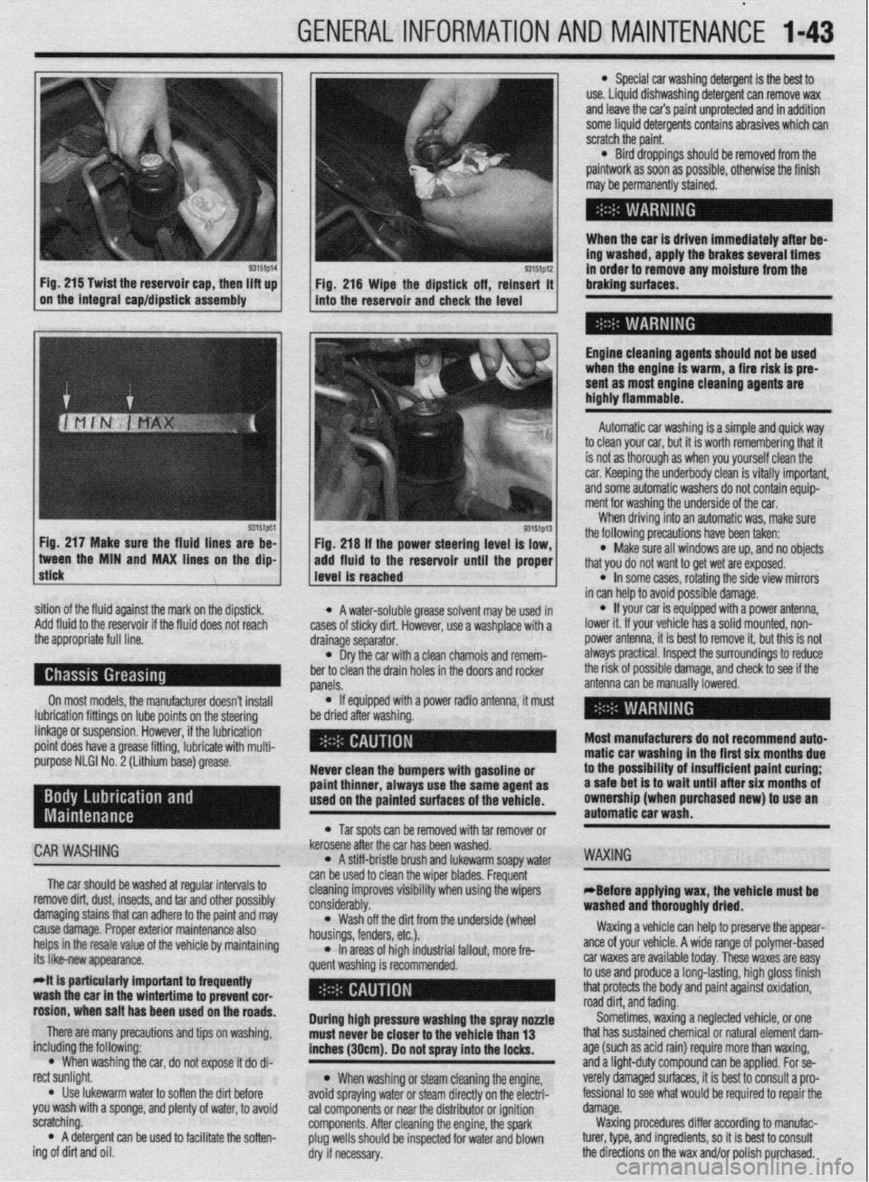
93151p14 93151p12 Fig. 215 Twist the reservoir cap, then lift up
I I
in order to remove any moisture from the
Fig. 216 Wipe the dipstick off, reinsert it braking surfaces.
on the integral cap/dipstick assembly
into the reservoir and check the level
I
Engine cleaning agents should not be used
when the engine is warm, a fire risk is pre-
sent as most engine cleaning agents are
highly flammable.
sition of the fluid against the mark on the dipstick,
Add fluid to the reservoir if the fluid does not reach
the appropriate full line.
On most models, the manufacturer doesn’t install
lubrication fittings on lube points on the steering
linkage or suspension. However, if the lubrication
point does have a grease fitting, lubricate with multi-
purpose NLGI No. 2 (Lithium base) grease.
CAR WASHING
The car should be washed at regular intervals to
remove dirt, dust, insects, and tar and other possibly
damaging stains that can adhere to the paint and may
cause damage. Proper exterior maintenance also
helps in the resale value of the vehicle by maintaining
its like-new appearance.
Mt is particularly important ta frequentiy
wash the car in the wintertime to prevent cor-
rosion, when salt has been used on the roads.
There are many precautions and tips on washing,
including the following:
l When washing the car, do not expose it do di-
rect sunlight.
. Use lukewarm water to soften the dirt before
you wash with a sponge, and plenty of water, to avoid
scratching.
l A detergent can be used to facilitate the soften-
ing of dirt and oil. * A water-soluble grease solvent may be used in
cases of sticky dirt. However, use a washplace with a
drainage separator.
l Dry the car with a clean chamois and remem-
ber to clean the drain holes in the doors and rocker
panels.
l If equipped with a power radio antenna, it must
be dried after washing.
Never clean the bumpers with gasoline or
paint thinner, always use the same agent as
used on the painted surfaces of the vehicle.
l Tar spots can be removed with tar remover or
kerosene after the car has been washed.
l A stiff-bristle brush and lukewarm soapy water
can be used to clean the wiper blades. Frequent
cleaning improves visibility when using the wipers
considerably.
l Wash off the did from the underside (wheel
housings, fenders, etc.).
l In areas of high industrial fallout, more fre-
quent washing is recommended.
During high pressure washing the spray nonle
must never be closer to the vehicle than 13
inches (30cm). Do not spray into the locks.
l When washing or steam cleaning the engine,
avoid spraying water or steam directly on the electri-
cal components or near the distributor or ignition
components. After cleaning the engine, the spark
plug wells should be inspected for water and blown
dry if necessary. Automatic car washing is a simple and quick way
to clean your car, but it is worth remembering that it
is not as thorough as when you yourself clean the
car. Keeping the underbody clean is vitally important,
and some automatic washers do not contain equip-
ment for washing the underside of the car.
When driving into an automatic was, make sure
the following precautions have been taken:
l Make sure all windows are up, and no objects
that you do not want to get wet are exposed.
l In some cases, rotating the side view mirrors
in can help to avoid possible damage.
l If your car is equipped with a power antenna,
lower it. If your vehicle has a solid mounted, non-
power antenna, it is best to remove it, but this is not
always practical. Inspect the surroundings to reduce
the risk of possible damage, and check to see if the
antenna can be manually lowered.
Most manufacturers do not recommend auto-
matic car washing in the first six months due
to the possibility of insufficient paint curing;
a safe bet is to wait until after six months of
ownership (when purchased new) to use an
automatic car wash.
WAXING
eBefore applying wax, the vehicle must be
washed and thoroughly dried.
Waxing a vehicle can help to preserve the appear-
ante of your vehicle. A wide range of polymer-based
car waxes are available today. These waxes are easy
to use and produce a long-lasting, high gloss finish
that protects the body and paint against oxidation,
road dirt, and fading.
Sometimes, waxing a neglected vehicle, or one
that has sustained chemical or natural element dam-
age (such as acid rain) require more than waxing,
and a light-duty compound can be applied. For se-
verely damaged surfaces, it is best to consult a pro-
fessional to see what would be required to repair the
damage.
Waxing procedures differ according to manufac-
turer, type, and ingredients, so it is best to consult
the directions on the wax and/or polish purchased.
Page 220 of 408
CHASSIS ELECTRICAL 647
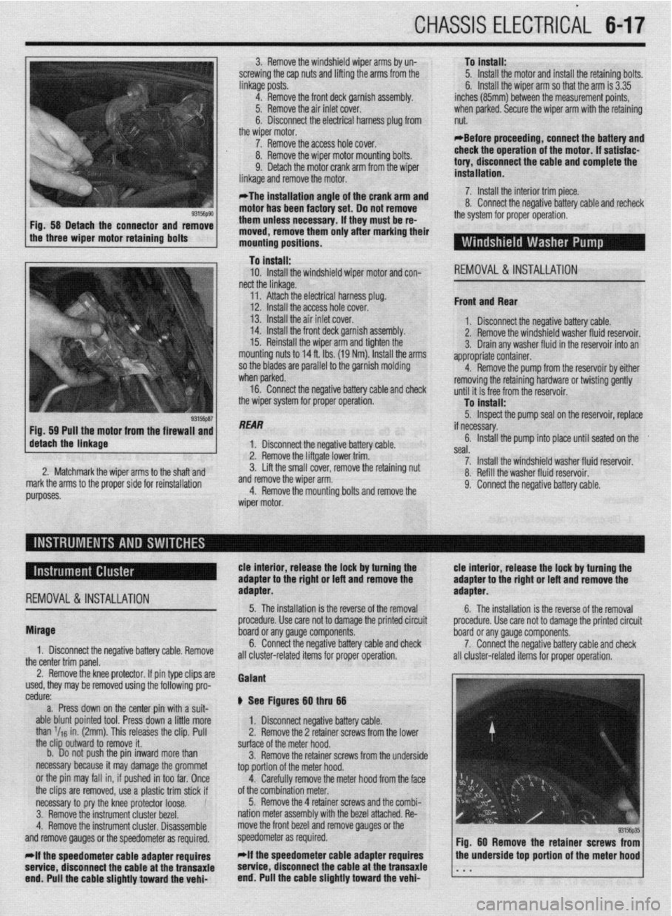
3. Remove the windshield wiper arms by un-
screwing the cap nuts and lifting the arms from the
linkage posts.
4. Remove the front deck garnish assembly.
Iver.
xl harness plug from
,I6 #-n\,LIr 5. Remove the air inlet c(
6. Disconnect the electric
the wiper motor.
7. Remove the access ho,, LIVIGil. To install:
5. Install the motor and install the retaining bolts.
6. Install the wiper arm so that the arm is 3.35
inches (85mm) between the measurement points,
when parked. Secure the wiper arm with the retaining
nut.
*Before proceeding, connect the battery and
8. Remove the wiper motor mounting bolts.
9. Detach the motor crank arm from the wiper
linkane and remnve the mntnr
motor has been factory set. Do not remove
them unless necessary. if they must be re-
moved, remove them only after marking their
mounting positions. check the operation of the motor. if satisfae-
tory, disconnect the cable and complete the
installation.
o. WIIIIW LIE Il~&WVt: vatreryoable and recheck
the system for proper operation.
..-
a- - ‘- _ _ _ . _ _ _
*The installation angle of the crank arm and 7. Install the interior trim piece
n II ^_^^^ IAL- -^I-I:..- L-AL--
To install:
10. Install the windshield wiper motor and con-
REMOVAL&INSTALLATION nect the linkage.
I 14. Install the front deck garnish assembly. I. YIV”“I1IIYVL VI” “UyuL’.” “UL’“‘, UUUIU. 2. Remove the windshield washer fluid resarvnir
’ 11. Attach the electrical harness plug.
12. Install the access hole cover.
13. Install the air inlet cover.
15. Reinstall the wiper arm and tighten the
mounting nuts to 14 ft. Ibs. (19 Nm). Install the arms
so the blades are parallel to the garnish molding -
Front and Rear
1 nivnnnprt the nonatiua haltorv rahlo
3. Drain any washer fluid in the reservoir into an
appropriate container.
4.
I when parked. Remove the pump from the reservoir by either
16. Connect the neaative batterv cable and check removing the retaining hardware or twisting gently
tlntil it is frpp frnm thP rosorvnir the wiper system for proper operation.
lo Install:
5. Inspect the pump seal on the reservoir, replace
/ de&h the linkage Fig 59 Pull the motor from the firewaii and
“‘%‘y 1 ““I”“,,,,,, the if necessary.
1 1 Disconn& thP rwnativo hatton/ rahlm 6. Install the pump into place until seated on the .I,” ~‘“p.L’,” YULL”‘, -YI”. liftgate lower trim. seal.
3: Lift the smatr CUVBI, I~IIIUV~ tilt: lfAdllllll~ IIUL II --. .-- -^- ^..^ .L^ -_,_:..:-- -.A 7. Install the windshield washer fluid reservoir. 2. Matchmark the wirier arms tn the shaft and A Refill thp wxhpr fllk-l rpqprvnir markthe arms to the proper side for reinstallation and remove the wiper arm.
4. Remove the mountina bolts and remove the “. .,“...S .V.” ....“III. ,*..*” IYUY..“m,.
9. Connect the negative battery cable.
REMOVAL&INSTALLATION
tie interior, release the lock by turning the tie interior, release the lock by turning the
adapter to the right or left and remove the adapter to the rigM or left and remove the
adapter. adapter.
5. The installation is the reverse of the removal
6. The installation is the reverse of the removal
Mirage
1. Disconnect the negative battery cable. Remove
the center trim panel. procedure. Use care not to damage the printed circuit procedure. Use care not to damage the printed circuit
board or any gauge components.
board or any gauge components.
6. Connect the negative battery cable and check
7. Connect the negative battery cable and check
all cluster-related items for proper operation. i III cluster-related items for proper operation.
2. Remove the knee protector. If pin type clips are
used, they may be removed using the following pro-
cedure:
a. Press down on the center pin with a suit-
able blunt pointed tool. Press down a little more
than ‘IIS in. (2mm). This releases the clip. Pull
the clip outward to remove it.
b. Do not push the pin inward more than
necessary because it may damage the grommet
or the pin may fall in, if pushed in too far. Once
the clips are removed, use a plastic trim stick if
necessary to pry the knee protector loose.
3. Remove the instrument cluster bezel.
4. Remove the instrument cluster. Disassemble
and remove gauges or the speedometer as required.
*if the speedometer cable adapter requires
setvice, disconnect the cable at the transaxie
end. Pull the cable slightly toward the vehi- Gaiant
@ See Figures Bg thru 66
1. Disconnect negative battery cable.
2. Remove the 2 retainer screws from the lower
surface of the meter hood.
3. Remove the retainer screws from the underside
top portion of the meter hood.
4. Carefully remove the meter hood from the face
of the combination meter.
5. Remove the 4 retainer screws and the combi-
nation meter assembly with the bezel attached. Re-
move the front bezel and remove gauges or the
speedometer as required.
*if the speedometer cable adapter requires
service, disconnect the cable at the transaxie
end. Pull the cable slightly toward the vehi-
Page 397 of 408
TROUBLESHOOTING 1145
d. Check the sensor wiring at the wheel sensors and the ABS control unit for a loose or
shorted wire and repair as necessary.
Brake Warninu Liaht a. Check the brakefluid~evel and check for possible leakage from the hydraulic lines and
seals. Top off brake fluid and repair leakage as necessary.
b. Check the brake linings for wear and replace as necessary.
c. Check for a loose or shorted brake warning light sensor or wire, and replace or repair
as necessary.
Oil Pressure Warning Light a. Stop the engine immediately. Check the engine oil level and check for a sudden and
rapid oil loss, such as a leaking oil line or oil pressure sensor, and repair or replace as
necessary.
b. Check the oil pressure sensor operation by substituting a known good sensor.
c. Check the oil pressure sensor wire for being shorted to ground. Disconnect the wire
from the oil pressure sensor and with the ignition in the ON position, but not running,
the oil pressure light should not be working. If the light works with the wire discon-
nected, check the sensor wire for being shorted to ground. Check the wire routing to
make sure the wire is not pinched and check for insulation damage. Repair or replace
the wire as necessary and recheck before starting the engine.
d. Remove the oil pan and check for a clogged oil pick-up tube screen.
Parking Brake Warning Light a. Check the brake release mechanism and verify the parking brake has been fully re-
leased.
b. Check the parking brake light switch for looseness or misalignment.
c. Check for a damaged switch or a loose or shorted brake light switch wire, and replace
or repair as necessary.
3. Warning li#ht(s) inoperative with iflnition on,
and engine not started
a. Check for a defective bulb by installing a known good bulb.
b. Check for a defective wire using the appropriate wiring diagram(s).
c. Check for a defective sending unit by removing and then grounding the wire at the
sending unit. If the light comes on with the ignition on when grounding the wire, re-
place the sending unit.
1. Turn siflnais or hazard iiflhts come on, but do not flash
a. Check for a defective flasher unit and replace as necessary.
2. Turn signals or hazard iiflhts do not function on either side
a. Check the fuse and replace, if defective.
b. Check the flasher unit by substituting a known good flasher unit.
c. Check the turn signal electrical system for a defective component, open circuit, short
circuit or poor ground.
3. Turn siflnais or hazard lights only work on one side
a. Check for failed bulbs and replace as necessary.
b. Check for poor grounds in both housings and repair as necessary.
4. One siflnai light does not work
a. Check for a failed bulb and replace as necessary.
b. Check for corrosion in the bulb socket, and clean and repair as necessary.
c. Check for a poor ground at the bulb socket, and clean and repair as necessary.
5. Turn signals flash too slowly
a. Check signal bulb(s) wattage and replace with lower wattage bulb(s). 6. Turn signals flash too fast
a, Check signal bulb(s) wattage and replace with higher wattage bulb(s).
b. Check for installation of the correct flasher unit and replace if incorrect.
7. Four-way hazard flasher indicator iiflhi inoperative
a. Verify that the exterior lights are functioning and, if so, replace indicator bulb.
b. Check the operation of the warning flasher switch and replace if defective.
0. Turn signal indicator ii#ht(s) do not work in either direction
a. Verify that the exterior lights are functioning and, if so, replace indicator bulb(s).
b. Check for a defective flasher unit by substituting a known good unit.
9. One turn signal indicator liflht does not work
a. Check for a defective bulb and replace as necessary.
b. Check for a defective flasher unit by substituting a known good unit.
1. Horn does not operate
a. Check for a defective fuse and replace as necessary.
b. Check for battery voltage and ground at horn electrical connections when pressing the
horn switch. If voltage is present, replace the horn assembly. If voltage or ground is
not present, refer to Chassis Electrical coverage for additional troubleshooting tech-
niques and circuit information.
2. Horn has an unusual tone
a. On single horn systems, replace the horn.
b. On dual horn systems, check the operation of the second horn. Dual horn systems
have a high and low pitched horn. Unplug one horn at a time and recheck operation.
Replace the horn which does not function.
c. Check for debris or condensation build-up in horn and verify the horn positioning. If
the horn has a single opening, adjust the opening downward to allow for adequate
drainage and to prevent debris build-up.
1. Windshield wipers do not operate
a. Check fuse and replace as necessary.
b. Check switch operation and repair or replace as necessary.
c. Check for corroded, loose, disconnected or broken wires and clean or repair as neces-
sary.
d. Check the ground circuit for the wiper switch or motor and repair as necessary.
2. Windshield wiper motor makes a humming noise, gets hot or blows
fuses
a. Wiper motor damaged internally; replace the wiper motor.
b. Wiper linkage bent, damaged or seized. Repair or replace wiper linkage as necessary.
3. Windshield wiper motor operates, but one or both wipers fail to move
a. Windshield wiper motor linkage loose or disconnected. Repair or replace linkage as
necessary.
b. Windshield wiper arms loose on wiper pivots. Secure wiper arm to pivot or replace
both the wiper arm and pivot assembly.
4. Windshield wipers will not park
a. Check the wiper switch operation and verify that the switch properly interrupts the
power supplied to the wiper motor.
b. If the wiper switch is functioning properly, the wiper motor parking circuit has failed.
Replace the wiper motor assembly. Operate the wiper motor at least one time before
installing the arms and blades to ensure correct positioning, then recheck using the
highest wiper speed on a wet windshield to make sure the arms and blades do not
contact the windshield trim.
1. Speedometer does not work to minimize sharp bends or kinks.
If the sheathing has been
damaged, replace the ca-
a. Check and verify that the speedometer cable is properly seated into the speedometer ble assembly.
assembly and the speedometer drive gear. b. Check the speedometer cable for adequate lubrication. Remove the cable, inspect for
b. Check the speedometer cable for breakage or rounded-off cable ends where the cable damage, clean, lubricate and reinstall. If the cable has been damaged, replace the ca-
seats into the speedometer drive gear and into the speedometer assembly. If damaged, ble.
broken or the cable ends are rounded off, replace the cable.
c. Check speedometer drive gear condition and replace as necessary. 3. Speedometer works intermittently
d. Install a known good speedometer to test for proper operation. If the substituted a. Check the cable and verify that the cable is fully installed and the fasteners are secure.
speedometer functions properly, replace the speedometer assembly. b. Check the cable ends for wear and rounding, and replace as necessary.
Page 407 of 408
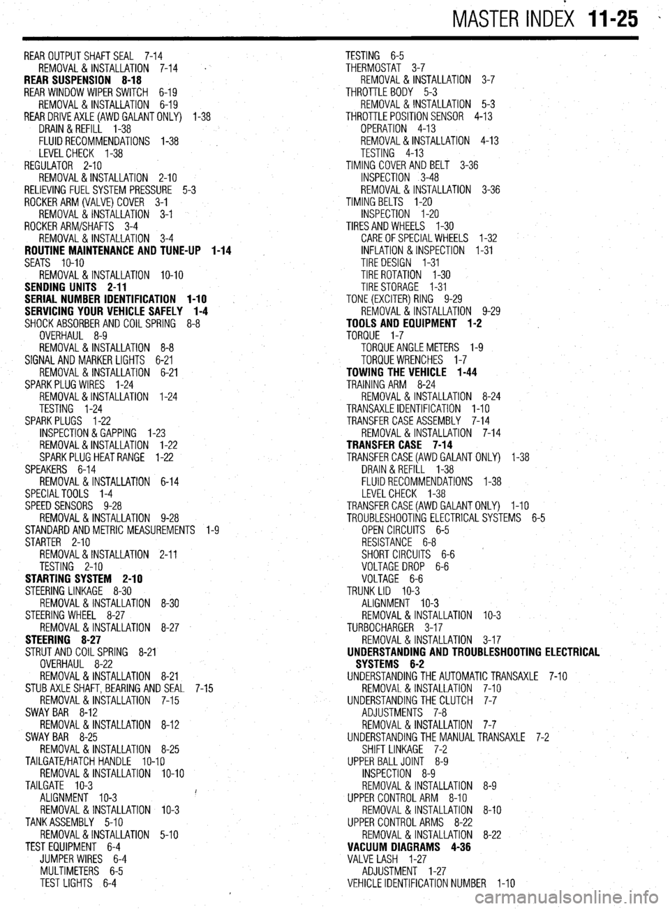
MASTER INDEX 11-25 -
REAROUTPUTSHAFTSEAL 7-14
TESTING 6-5
REMOVAL & INSTALLATION 7-14
' THERMOSTAT 3-7
REAR SUSPENSION 8-18 REMOVAL & INSTALLATION 3-7
REAR WINDOW WIPER SWITCH 6-19 THROTTLE BODY 5-3
REMOVAL&INSTALLATION 6-19 REMOVAL & INSTALLATION 5-3
REARDRlVEAXLE(AWDGALANTONLY) l-38
THROTTLEPOSITIONSENSOR 4-13
DRAIN &REFILL 1-38
OPERATION 4-13
FLUIDRECOMMENDATIONS 1-38 , REMOVAL&INSTALLATION 4-13
LEVELCHECK l-38
TESTING 4-13
REGULATOR 2-10 TIMING COVERAND BELT 3-36
REMOVAL&INSTALLATION 2-10
INSPECTION 3-48
RELIEVING FUELSYSTEM PRESSURE 5-3 REMOVAL & INSTALLATION 3-36
ROCKERARM(VALVE)COVER 3-1
TIMING BELTS l-20
REMOVAL & INSTALLATION 3-1
INSPECTION I-20
ROCKER ARM/SHAFTS 3-4
TIRESANDWHEELS I-30
REMOVAL & INSTALLATION 3-4
CAREOFSPECIALWHEELS l-32
ROUTINE MAINTENANCE AND TUNE-UP 1-14 INFLATION & INSPECTION I-31
SEATS IO-IO
TIRE DESIGN I-31
REMOVAL&INSTALLATION IO-IO TIRE ROTATION I-30
SENDING UNITS 2-11
TIRESTORAGE I-31
SERIAL NUMBER IDENTIFICATION l-10
TONE (EXCITER) RING 9-29
SERVICING YOUR VEHICLE SAFELY I-4
REMOVAL & INSTALLATION 9-29
SHOCKABSORBERAND COILSPRING 8-8
TOOLS AND EQUIPMENT 1-2
OVERHAUL 8-9
TORQUE 1-7
REMOVAL&INSTALLATION 8-8 TORQUEANGLEMETERS l-9
SIGNAL AND MARKER LIGHTS 6-21
TORQUEWRENCHES l-7
REMOVAL & INSTALLATION 6-21
TOWING THE VEHICLE 1-44
SPARKPLUG WIRES 1-24
TRAINING ARM 8-24
REMOVAL&INSTALLATION 1-24
REMOVAL & INSTALLATION 8-24
TESTING 1-24
TRANSAXLEIDENTIFICATION I-10
SPARKPLUGS l-22
TRANSFER CASE ASSEMBLY 7-14
INSPECTION &GAPPING l-23
REMOVAL & INSTALLATION 7-14
REMOVAL&INSTALLATION 1-22
TRANSFER CASE 7-14
SPARKPLUGHEATRANGE 1-22
TRANSFERCASE(AWD GALANT ONLY) 1-38
SPEAKERS 6-14
DRAIN &REFILL 1-38
REMOVAL & INSTALLATION 6-14
FLUIDRECOMMENDATIONS 1-38
SPECIALTOOLS 1-4
LEVELCHECK 1-38
SPEED SENSORS 9-28
TRANSFERCASE(AWDGALANTONLY) I-10
REMOVAL & INSTALLATION 9-28
TROUBLESHOOTING ELECTRICALSYSTEMS 6-5
STANDARDANDMETRIC MEASUREMENTS l-9
OPEN CIRCUITS 6-5
STARTER 2-10
RESISTANCE 6-8
REMOVAL&INSTALLATION 2-11
SHORT CIRCUITS 6-6
TESTING 2-10
VOLTAGEDROP 6-6
STARTING SYSTEM 2-10
VOLTAGE 6-6
STEERING LINKAGE 8-30
TRUNK LID IO-3
REMOVAL &INSTALLATION 8-30
ALIGNMENT IO-3
STEERING WHEEL 8-27
REMOVAL & INSTALLATION IO-3
REMOVAL &INSTALLATION 8-27
TURBOCHARGER 3-17
STEERING 8-27
REMOVAL & INSTALLATION 3-17
STRUT AND COIL SPRING
8-21
UNDERSTANDING AND TROUBLESHOOTING ELECTRICAL
OVERHAUL 8-22
SYSTEMS 6-2
REMOVAL & INSTALLATION 8-21
UNDERSTANDINGTHEAUTOMATICTRANSAXLE 7-10
STUBAXLESHAFT,BEARlNG AND SEAL 7-15
REMOVAL & INSTALLATION 7-10
REMOVAL&INSTALLATION 7-15
UNDERSTANDINGTHECLUTCH 7-7
SWAY BAR 8-12
ADJUSTMENTS 7-8
REMOVAL 8, INSTALLATION 8-12
REMOVAL&INSTALLATION 7-7
SWAY BAR 8-25
UNDERSTANDINGTHE MANUALTRANSAXLE 7-2
REMOVAL&INSTALLATION 8-25
SHIFT LINKAGE 7-2
TAILGATE/HATCH HANDLE lo-19
UPPER BALLJOINT 8-9
REMOVAL &INSTALLATION lo-10
INSPECTION 8-9
TAILGATE IO-3
REMOVAL &INSTALLATION 8-9
ALIGNMENT IO-3 i'
UPPER CONTROLARM 8-10
REMOVAL & INSTALLATION IO-3
REMOVAL & INSTALLATION 8-10
TANKASSEMBLY 5-10
UPPER CONTROL ARMS 8-22
REMOVAL&INSTALLATION 5-10
REMOVAL & INSTALLATION 8-22
TEST EQUIPMENT 6-4
VACUUM DIAGRAMS 4-36
JUMPER WIRES 6-4
VALVE LASH 1-27
MULTIMETERS 6-5
ADJUSTMENT 1-27
TEST LIGHTS 6-4
VEHICLE IDENTIFICATION NUMBER I-10