alternator MITSUBISHI DIAMANTE 1900 Owner's Manual
[x] Cancel search | Manufacturer: MITSUBISHI, Model Year: 1900, Model line: DIAMANTE, Model: MITSUBISHI DIAMANTE 1900Pages: 408, PDF Size: 71.03 MB
Page 106 of 408
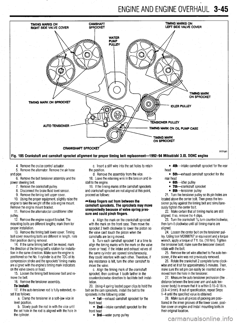
ENGlNEANDENGlNEOVERHiUL 3-45
TIMINQ MARKS ON RIQHT SIDE VALVE COVER TIMING MARKS ON LEFT SIDE VALVE COVER
CRANKSHAFT SPROCKETS
91251gb5 :ig. 185 Crankshaft and camshaft sprocket alignment for proper timing belt replacement-1992-94 Mitsubishi 3.OL DOHC engine
4. Remove the cruise control actuator.
5. Remove the alternator. Remove the air hose
and pipe.
6. Remove the belt tensioner assembly and the
power steering belt.
7. Remove the crankshaft pulley.
8. Disconnect the brake fluid level sensor.
9. Remove the timing belt upper cover.
10. Using the proper equipment, slightly raise the
engine to take the weight off the side engine mount.
Remove the engine mount bracket.
11. Remove the alternator/air conditioner idler
pulley.
12. Remove the engine support bracket. The
mounting bolts are different lengths; mark them for
proper installation.
13. Remove the timing belt lower cover. Timing
bolt cover mounting bolts are different in length, note
their position during removal.
14. If the same timing belt will be reused, mark
the direction of the timing belt’s rotation for installa-
tion in the same dlrection. Make sure the engine is
positioned so the No. 1 cylinder is at the TDC of its
compression stroke and the sprockets’timing marks
are aligned with the engine’s timing mark indicators
on the valve covers or head.
15. Loosen the timing belt tensioner bolt and re-
move the belt.
16. Remove the tensioner assembly.
To install:
17. If the auto tensioner rod is fully extended, re-
set it as follows:
a. Clamp the tensioner in a soft-jaw vice in
level position.
b. Slowly push the rod in with the vice until
the set hole in the rod is aligned with the hole in
the cylinder. c. Insert a stiff wire into the set holes to retain
the position.
d. Remove the assembly from the vice.
18. Leave the retaining wire in the tension and in-
stall to the engine.
19. If the timing marks of the camshaft sprockets
and crankshaft sprocket are not aligned at this point,
proceed as follows:
*Keep fingers out from between the
camshaft sprockets. The sprockets may move
unexpectedly because of valve spring pres-
sure and could pinch fingers.
a. Align the mark on the crankshaft sprocket
with the mark on the front case. Then move the
sprocket 2 teeth clockwise to lower the piston so
the valve can’t touch the piston when the
camshafts are being moved.
b. Turn each camshaft sprocket 1 at a time to
align the timing marks with the mark on the valve
cover or head. If the intake and exhaust valves of
the same cylinder are opened simultaneously,
they could interfere with each other. Therefore, if
any resistance is felt, turn the other camshaft to
move the valve.
c. Align the timing mark of the crankshaft
sprocket, then continue 1 tooth farther in the
counterclockwise direction to facilitate belt instal-
lation.
20. Using 4 spring loaded paper clips to hold the
belt on the cam sprockets, install the belt to the
sprockets in the following order:
l M-exhaust camshaft sprocket for the
front head
l 2nd-intake camshaft sprocket for the
front head
l trd-water pump pulley
l 5th-exhaust camshaft sprocket for tile
rear head
l Ah-intake camshaft sprocket for the rear
l Gth-idler pulley head l 7th-crankshaft sprocket l 8th-tensioner pulley
21. Turn the tensioner pulley so its pin holes are
located above the center bolt. Then press the ten-
sioner pulley against the timing belt and simultane-
ously tighten the center bolt.
22. Make certain that all timing marks are still
aligned. If so, remove the 4 clips.
23. Turn the crankshaft l/d turn counterclockwise,
then turn it clockwise until all timing marks are
aligned.
24. Loosen the center bolt on the tensioner pul-
ley. Using tool MD998767 or equivalent and a torque
wrench, apply a torque of 7 ft. Ibs. (10 Nm). Tighten
the tensioner bolt; make sure the tensioner doesn’t
rotate with the bolt.
25. Remove the set wire attached to the auto ten-
sioner, if the wire was not previously removed.
26. Rotate the crankshaft 2 complete turns clock-
wise and let it sit for approximately 5 minutes. Then,
make sure the set pin can easily be inserted and re-
moved from the hole in the tensioner.
27. Measure the auto tensioner protrusion (the
distance between the tensioner arm and auto ten-
sioner body) to ensure that it is within 0.15-0.18 in.
(3.8-4 5mm). If out of specification, repeat Steps
l-4 until the specified value is obtained.
28. Make sure all pieces of packing are posi-
tioned in the inner grooves of the lower cover, posi-
tion cover on engine and install mounting bolts in
their original location.
Page 107 of 408
3-46 ENGINEANDENGINEOVERHAUL
29. Install the engine support bracket and secure
using mounting bolts in their original location. Lubri-
cate the reaming area of the reamer bolt and tighten
slowly.
30. Install the idler pulley.
31. Install the engine mount bracket. Remove the
engine support fixture.
32. Make sure all pieces of packing are posi-
tioned in the inner grooves of the upper cover and in-
stall.
33. Connect the brake fluid level sensor.
34. Install the crankshaft pulley. Tighten the bolt
to 130-137ft. Ibs. (180-190 Nm).
35. install the belt tensioner assembly and the
power steering belt.
36 install the air hose and pipe.
37 Install the alternator.
38. Install the cruise control actuator.
39. Install the engine undercover.
40. Connect the negative battery cable.
199546 MODELS
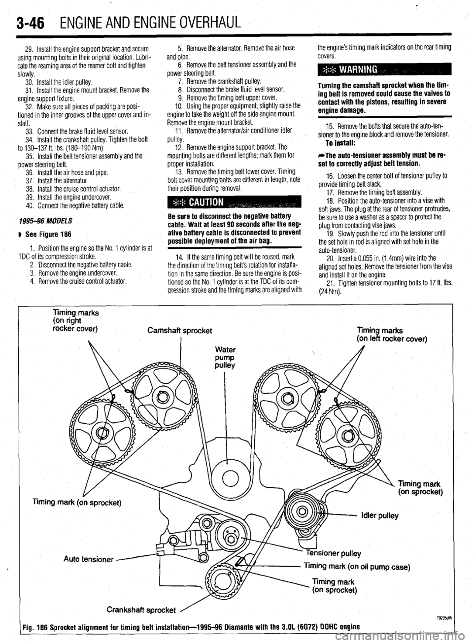
# See Figure 186
1, Position the engine so the No. 1 cylinder is at
TDC of its compression stroke.
2. Disconnect the negative battery cable.
3. Remove the engine undercover.
4 Remove the cruise control actuator. 5. Remove the alternator, Remove the air hose the engine’s timing mark indicators on the rear timing
and pipe.
6. Remove the belt tensioner assembly and the
power steering belt.
7. Remove the crankshaft pulley.
8. Disconnect the brake fluid level sensor.
9. Remove the timing belt upper cover.
10. Using the proper equipment, slightly raise the
engine to take the weight off the side engine mount.
Remove the engine mount bracket.
11, Remove the alternator/air conditioner idler
..,,ll^,. covers.
Turning the camshaft sprocket when the tim-
ing belt is removed could cause the valves to
contact with the pistons, resulting in severe
engine damage.
15. Remove the bolts that secure the auto-ten-
sioner to the engine block and remove the tensioner.
pu,ey. 12. Remove the engine support bracket. The To install:
mounting bolts are different lengths; mark them for
orooer installation. *The auto-tensioner assembly must be re-
set to correctlv adiust belt tension. , . 13. Remove the timing belt lower cover. Timing
bolt cover mounting bolts are different in length, note
their position during removal.
Be sure to disconnect the negative battery
cable. Wait at least 90 seconds after the neg-
ative battery cable is disconnected to prevent
possible deployment of the air bag.
14. If the same timing belt WIII be reused, mark
the direction of the trming belts rotation for installa-
tion In the same direction, Be sure the engine is posi-
tioned so the No. 1 cylinder is at the TDC of its com-
pression stroke and the timing marks are aligned with _ -
16. Loosen the center bolt of tensioner pulley to
provide timing belt slack.
17. Remove the timing belt assembly.
18. Posrtion the auto-tensioner into a vise with
soft iaws. The olua at the rear of tensioner protrudes,
be sure to usea v&her as a spacer to protect the
plug from contacting vise jaws.
19. Slowly push the rod mto the tensioner until
the set hole in rod is aligned with set hole in the
auto-tensioner.
20. Insert a 0.055 in. (1.4mm) wire into the
aligned set holes, Remove the tensioner from the vise
and install it on the engine.
21. Tighten tensioner mounting bolts to 17 ft. Ibs.
(24 Nm).
Timing marks
(on right
rocker cover)
Camshaft sprocket
Timing marks
mark (on oil pump case)
Crankshaft sprocket
Fig. 186 Sprocket alignment for timing belt installation-1995116 Diamante with the 3.N (6672) DDDD engine
Page 120 of 408
ENGINEAND ENGINEOVERHAUL 3-59
Most of the cleaning process can be carried out
with common hand tools and readily available sol-
vents or solutions. Carbon deposits can be chipped
away using a hammer and a hard wooden chisel. Old
gasket material and varnish or sludge can usually be
removed using a scraper and/or cleaning solvent. Ex-
tremely stubborn deposits may require the use of a
power drill wrth a wire brush. If using a wire brush,
use extreme care around any critical machined sur-
faces (such as the gasket surfaces, bearing saddles,
cylinder bores, etc.). USE OF A WIRE BRUSH IS NOT
RECOMMENDED ON ANY ALUMINUM COMPO-
NENTS Always follow any safety recommendations
given by the manufacturer of the tool and/or solvent.
You should always wear eye protection during any
cleaning process involvrng scraping, chipping or
spraying of solvents.
An alternative to the mess and hassle of cleaning
the parts yourself is to drop them off at a local garage
or machine shop. They will, more than likely, have
the necessary equrpment to properly clean all of the
parts for a nominal fee.
Always wear eye protection during any clean-
ing process involving scraping, chipping or
spraying of solvents.
Remove any oil galley plugs, freeze plugs and/or
pressed-in bearings and carefully wash and degrease
all of the engine components including the fasteners
and bolts. Small parts such as the valves, springs,
etc., should be placed in a metal basket and allowed
to soak. Use pipe cleaner type brushes, and clean all
passageways in the components. Use a ring ex-
pander and remove the rings from the pistons. Clean
the piston ring grooves with a special tool or a piece
of broken ring Scrape the carbon off of the top of the
piston. You should never use a wire brush on the
pistons. After preparing all of the piston assemblies
in this manner, wash and degrease them again.
Use extreme care when cleaning around the
cylinder head valve seats. A mistake or slip
may cost you a new seat.
When cleaning the cylinder head, remove carbon
from the combustron chamber with the valves in-
stalled. This will avoid damaging the valve seats.
:ig. 234 Drill out the damaged threads with
he specified size bit. Be sure to drill corn.
rletely through the hole or to the bottom oi
I blind hole REPAIRING DAMAGEDTHREADS
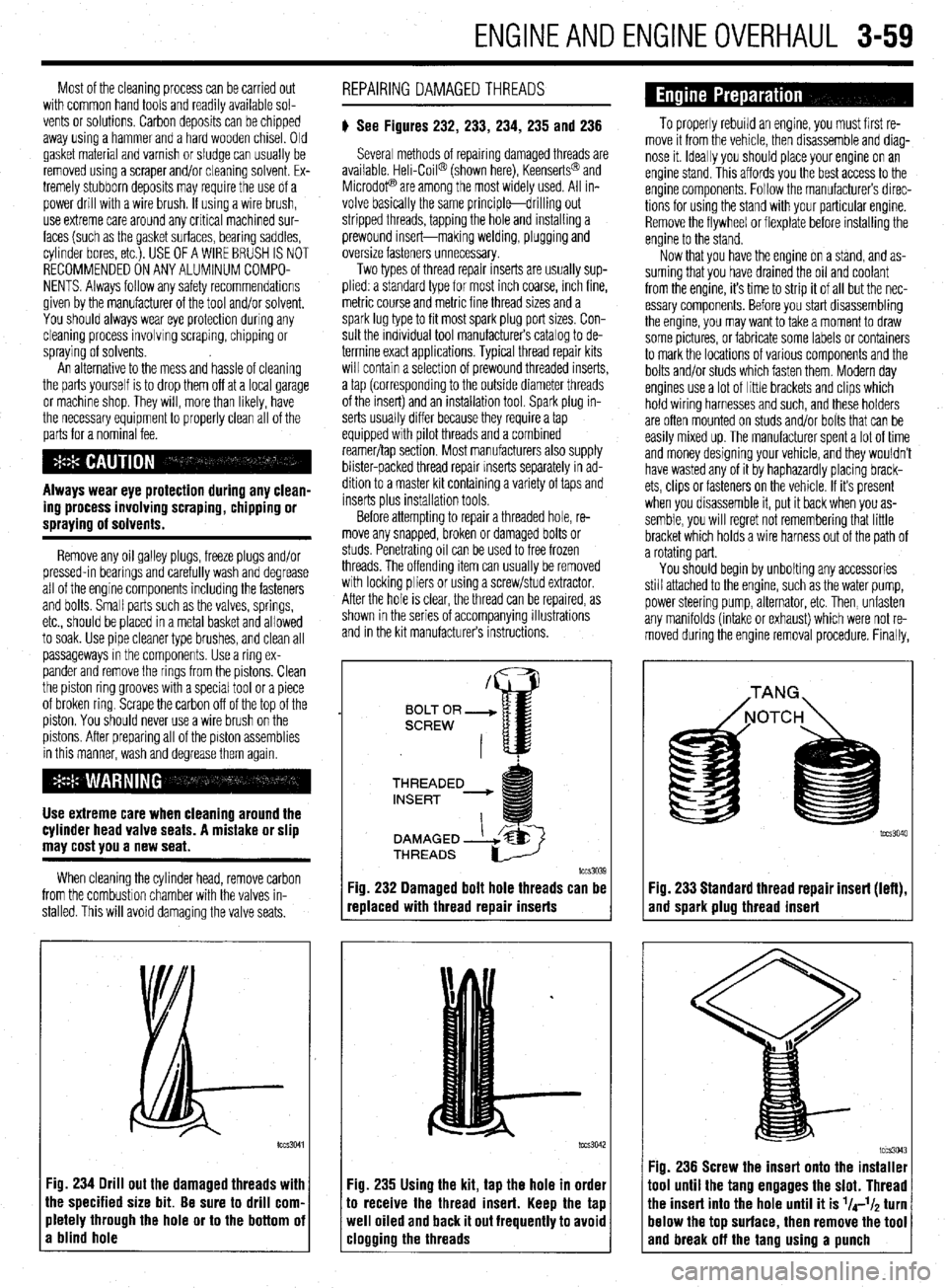
# See Figures 232, 233, 234, 235 and 236
Several methods of repairing damaged threads are
available Heli-Coil@ (shown here), Keenserts@ and
Microdop are among the most widely used. All in-
volve basically the same principle-drilling out
stripped threads, tapping the hole and installing a
prewound insert-making welding, plugging and
oversize fasteners unnecessary.
Two types of thread repair inserts are usually sup-
plied: a standard type for most inch coarse, rnch fine,
metric course and metrrc fine thread sizes and a
spark lug type to fit most spark plug port sizes. Con-
sult the individual tool manufacturers catalog to de-
termine exact applications. Typical thread repair kits
will contain a selection of prewound threaded inserts,
a tap (corresponding to the outside diameter threads
of the insert) and an installation tool. Spark plug in-
serts usually differ because they require a tap
equipped wrth pilot threads and a combined
reamer/tap section. Most manufacturers also supply
blister-packed thread repair Inserts separately in ad-
dition to a master kit containing a variety of taps and
inserts plus installation tools
Before attempting to repair a threaded hole, re-
move any snapped, broken or damaged bolts or
studs. Penetrating oil can be used to free frozen
threads. The offending item can usually be removed
with locking pliers or using a screw/stud extractor.
After the hole is clear, the thread can be reparred, as
shown in the series of accompanying illustrations
and in the krt manufacturers instructions.
THREADED
lCCS3039
replaced with thread repair inserts
:ig. 235 Using the kit, tap the hole in order
o receive the thread insert. Keep the tap
veil oiled and back it out frequently to avoid
:logging the threads
To properly rebuild an engine, you must first re-
move it from the vehicle, then disassemble and diag-
nose it. Ideally you should place your engine on an
engine stand. This affords you the best access to the
engine components. Follow the manufacturers direc-
tions for using the stand with your particular engine.
Remove the flywheel or flexplate before installing the
engine to the stand.
Now that you have the engine on a stand, and as-
suming that you have drained the oil and coolant
from the engine, it’s time to strip it of all but the nec-
essary components. Before you start disassembling
the engine, you may want to take a moment to draw
some pictures, or fabricate some labels or containers
to mark the locations of various components and the
bolts and/or studs which fasten them. Modern day
engines use a lot of little brackets and clips which
hold wiring harnesses and such, and these holders
are often mounted on studs and/or bolts that can be
easily mixed up. The manufacturer spent a lot of time
and money designing your vehicle, and they wouldn’t
have wasted any of it by haphazardly placing brack-
ets, clips or fasteners on the vehicle. If it’s present
when you disassemble it, put it back when you as-
semble, you will regret not remembering that little
bracket which holds a wire harness out of the path of
a rotating part.
You should begin by unbolting any accessories
still attached to the engine, such as the water pump,
power steering pump, alternator, etc. Then, unfasten
any manifolds (intake or exhaust) which were not re-
moved during the engine removal procedure. Finally,
Fig. 233 Standard thread repair insert (left),
and spark plug thread insert
im3043 Fig. 236 Screw the insert onto the installer
1001 until the tang engages the slot. Thread
‘he insert into the hole until it is l/4-l/~ turn
lelow the top surface, then remove the tool
and break off the tano usina a uunch
Page 205 of 408
6-2 CHASSIS ELECTRICAL
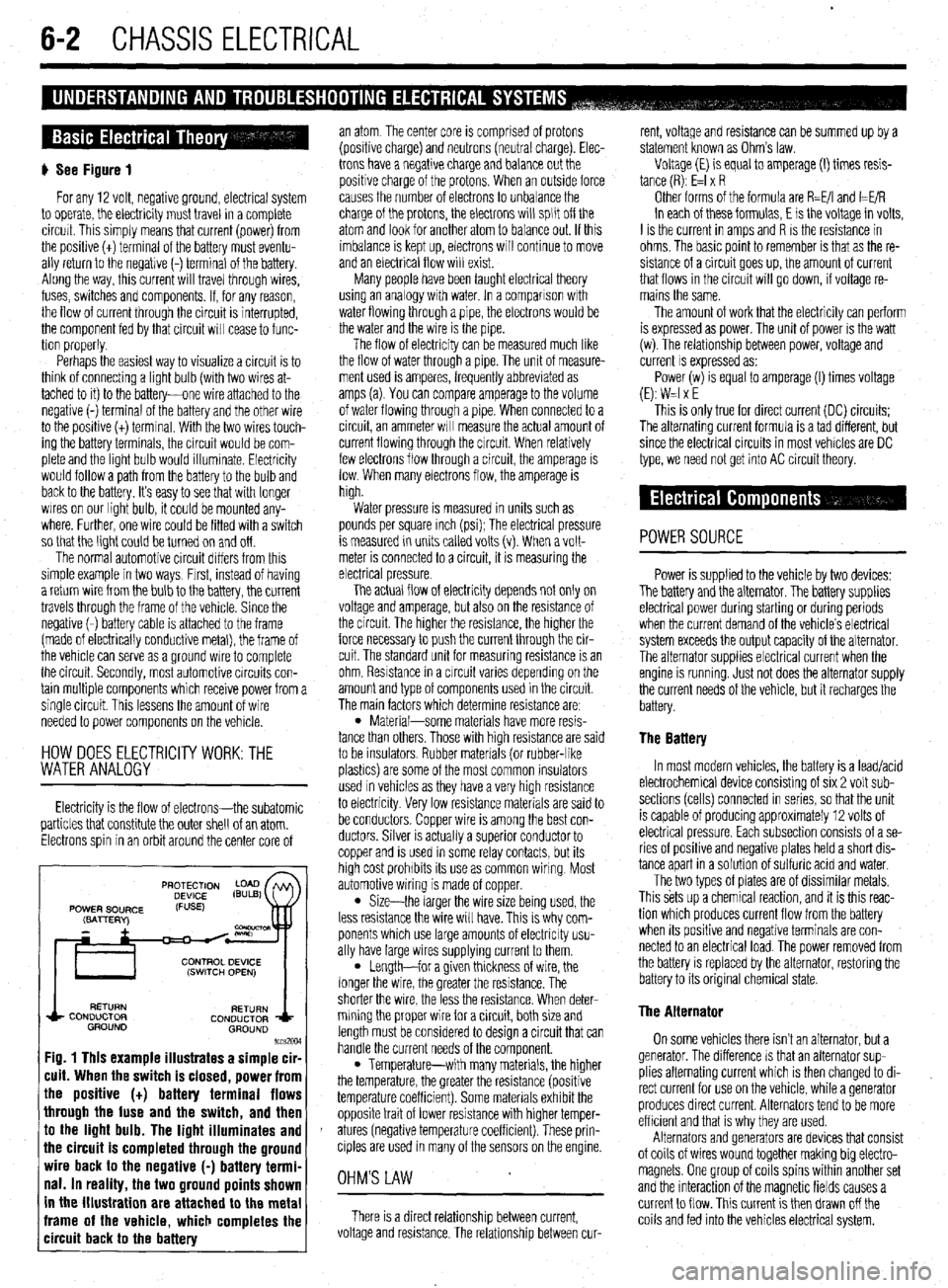
) See Figure 1
For any 12 volt, negative ground, electrical system
to operate, the electricity must travel in a complete
circurt. This simply means that current (power) from
the posibve (t) terminal of the battery must eventu-
ally return to the negative (-) terminal of the battery.
Along the way, this current will travel through wires,
fuses, switches and components. If, for any reason,
the flow of current through the circuit is interrupted,
the component fed by that circuit will cease to func-
tion properly.
Perhaps the easiest way to visualize a circuit is to
think of connecting a light bulb (with two wires at-
tached to it) to the battery-one wire attached to the
negative (-) terminal of the battery and the other wire
to the positive (t) terminal. With the two wires touch-
ing the battery terminals, the circuit would be com-
plete and the light bulb would illummate. Electricity
would follow a path from the battery to the bulb and
back to the battery. It’s easy to see that wrth longer
wires on our light bulb, it could be mounted any-
where. Further, one wire could be fitted with a switch
so that the light could be turned on and off.
The normal automotive circuit differs from this
simple example in two ways, Frrst, instead of having
a return wire from the bulb to the battery, the current
travels through the frame of the vehicle. Since the
negative (-) battery cable is attached to the frame
(made of electrically conductive metal), the frame of
the vehicle can serve as a ground wire to complete
the circuit. Secondly, most automotive circuits con-
tain multiple components which receive power from a
single circuit. This lessens the amount of wire
needed to power components on the vehicle.
HOW DOES ELECTRlClTYWORK:THE
WATER ANALOGY
Electricity is the flow of electrons-the subatomic
particles that constitute the outer shell of an atom.
Electrons spin in an orbit around the center core of
RETURN
RETURN
CONDUCTOR
CONDUCTOR
GROUND
GROUND
lccs2w
Fig. 1 This example illustrates a simple cir-
cuit. When the switch is closed, power from
the positive (t) battery terminal flows
through the fuse and the switch, and then
to the light bulb. The light illuminates and
the circuit is completed through the ground
wire back to the negative (-) battery termi-
nal. In reality, the two ground points shown
in the illustration are attached to the metal
frame of the vehicle, which completes the
circuit back to the battery
an atom The center core is comprised of protons
(positive charge) and neutrons (neutral charge). Elec-
trons have a negative charge and balance
out the
positive charge of the protons. When an outside force
causes the number of electrons to unbalance the
charge of the protons, the electrons will split off the
atom and look for another atom to balance out. If this
imbalance is kept up, electrons will continue to move
and an electrical flow will exist.
Many people have been taught electrical theory
using an analogy with water. In a comparison wrth
water flowing through a pipe, the electrons would be
the water and the wire is the pipe.
The flow of electricity can be measured much like
the flow of water through a pipe. The unit of measure-
ment used is amperes, frequently abbreviated as
amps (a). You can compare amperage to the volume
of water flowing through a pipe. When connected to a
circuit, an ammeter WIII measure the actual amount of
current flowing through the circuit. When relatively
few electrons flow through a circuit, the amperage is
low. When many electrons flow, the amperage is
high.
Water pressure is measured in units such as
pounds per square inch (psi); The electrical pressure
is measured in unrts called volts (v). When a volt-
meter is connected to a circuit, it is measuring the
electrical pressure.
The actual flow of electricity depends not only on
voltage and amperage, but also on the resistance of
the circuit The higher the resistance, the higher the
force necessary to push the current through the cir-
cuit. The standard unit for measuring resistance is an
ohm. Resistance in a crrcuit varies dependmg on the
amount and type of components used in the circuit.
The main factors which determine resistance are:
l Material-some materials have more resis-
tance than others Those with high resistance are said
to be insulators Rubber materials (or rubber-like
plashcs) are some of the most common insulators
used in vehicles as they have a very high resistance
to electricity Very low resistance materials are said to
be conductors. Copper wire is among the best con-
ductors. Silver is actually a superior conductor to
copper and is used in some relay contacts, but its
high cost prohibits its use as common wiring Most
automotive wiring is made of copper.
l Size-the larger the wire size being used, the
less resistance the wire will have. This IS why com-
ponents which use large amounts of electricity usu-
ally have large wires supplying current to them.
l Length-for a given thickness of wire, the
longer the wire, the greater the resistance. The
shorter the wire, the less the resistance. When deter-
mining the proper wire for a circuit, both size and
length must be considered to design a circuit that can
handle the current needs of the component.
l Temperature-with many materials, the higher
the temperature, the greater the resistance (positive
temperature coefficient). Some materials exhibit the
opposite trait of lower resistance with higher temper-
atures (negative temperature coefficient). These prin-
ciples are used in many of the sensors on the engine
OHM'S LAW
There is a direct relationship between current,
voltage and resistance. The relationship between cur- rent, voltage and resistance can be summed up by a
statement known as Ohm’s law.
Voltage (E) is equal to amperage (I) times resis-
tance (R): E=l x R
Other forms of the formula are R=E/I and I=E/R
In each of these formulas, E is the voltage in volts,
I is the current in amps and R IS the resistance in
ohms. The basic point to remember is that as the re-
sistance of a circuit goes up, the amount of current
that flows in the circuit will go down, if voltage re-
mains the same.
The amount of work that the electricity can perform
is expressed as power. The unit of power is the watt
(w). The relationship between power, voltage and
current
IS expressed as:
Power(w) is equal to amperage (I) times voltage
(E): W=l x E
This is only true for direct current (DC) circuits:
The alternating current formula is a tad different, but
since the electrical circuits in most vehicles are DC
type, we need not get into AC circuit theory.
POWERSOURCE
Power is supplied to the vehicle by two devices:
The battery and the alternator. The battery supplies
electrical power during starting or during periods
when the current demand of the vehicle’s electrical
system exceeds the output capacity of the alternator.
The alternator supplies electrical current when the
engine is running
Just not does the alternator supply
the current needs of the vehicle, but it recharges the
battery.
The Battery
In most modern vehicles, the battery is a lead/acid
electrochemical device consisting of six 2 volt sub-
sections (cells) connected in series, so that the unit
is capable of producing approximately 12 volts of
electrical pressure. Each subsection consists of a se-
ries of positive and negative plates held a short dis-
tance apart in a solutron of sulfuric acid and water.
The two types of plates are of dissimilar metals,
This sets up a chemrcal reaction, and it is this reac-
tion which produces current flow from the battery
when Its positive and negattve terminals are con-
nected to an electrical load. The power removed from
the battery is replaced by the alternator, restoring the
battery to its original chemical state.
The Alternator
On some vehicles there isn’t an alternator, but a
generator. The difference IS that an alternator sup-
plies alternating current which is then changed to di-
rect current for
use on the vehicle, while a generator
produces direct current. Alternators tend to be more
efficient and that is why they are used.
Alternators and generators are devices that consist
of coils of wires wound together making big electro-
magnets. One group of coils spins within another set
and the interaction of the magnetic fields causes a
current to flow. This current is then drawn off the
coils and fed into the vehicles electrical system.
Page 210 of 408
I I
CHASSIS ELECTRICAL 6-7
When working on any electrical component on the
vehicle, it is always a good idea to disconnect the
negative (-) battery cable. This will prevent potential
damage to many sensitive electrical components
such as the Powertrain Control Module (PCM), radio,
alternator, etc.
*Any time you disengage the battery cables,
it is recommended that you disconnect the negative (-) battery cable first. This will pre-
vent your accidentally grounding the positive
(+) terminal to the body of the vehicle when
disconnecting it, thereby preventing damage
to the above mentioned components.
Before you disconnect the cable(s), first turn the
ignition to the OFF position. This will prevent a draw
on the battery which could cause arcing (electricity
trying to ground itself to the body of a vehicle, just
like a spark plug jumping the gap) and, of course, damaging some components such as the alternator
diodes.
When the battery cable(s) are reconnected (nega-
tive cable last), be sure to check that your lights,
windshield wipers and other electrically operated
safety components are all working correctly. If your
vehicle contains an Electronically Tuned Radio (ETR),
don’t forget to also reset your radio stations. Ditto for
the clock.
SERVICE PRECAUTIONS
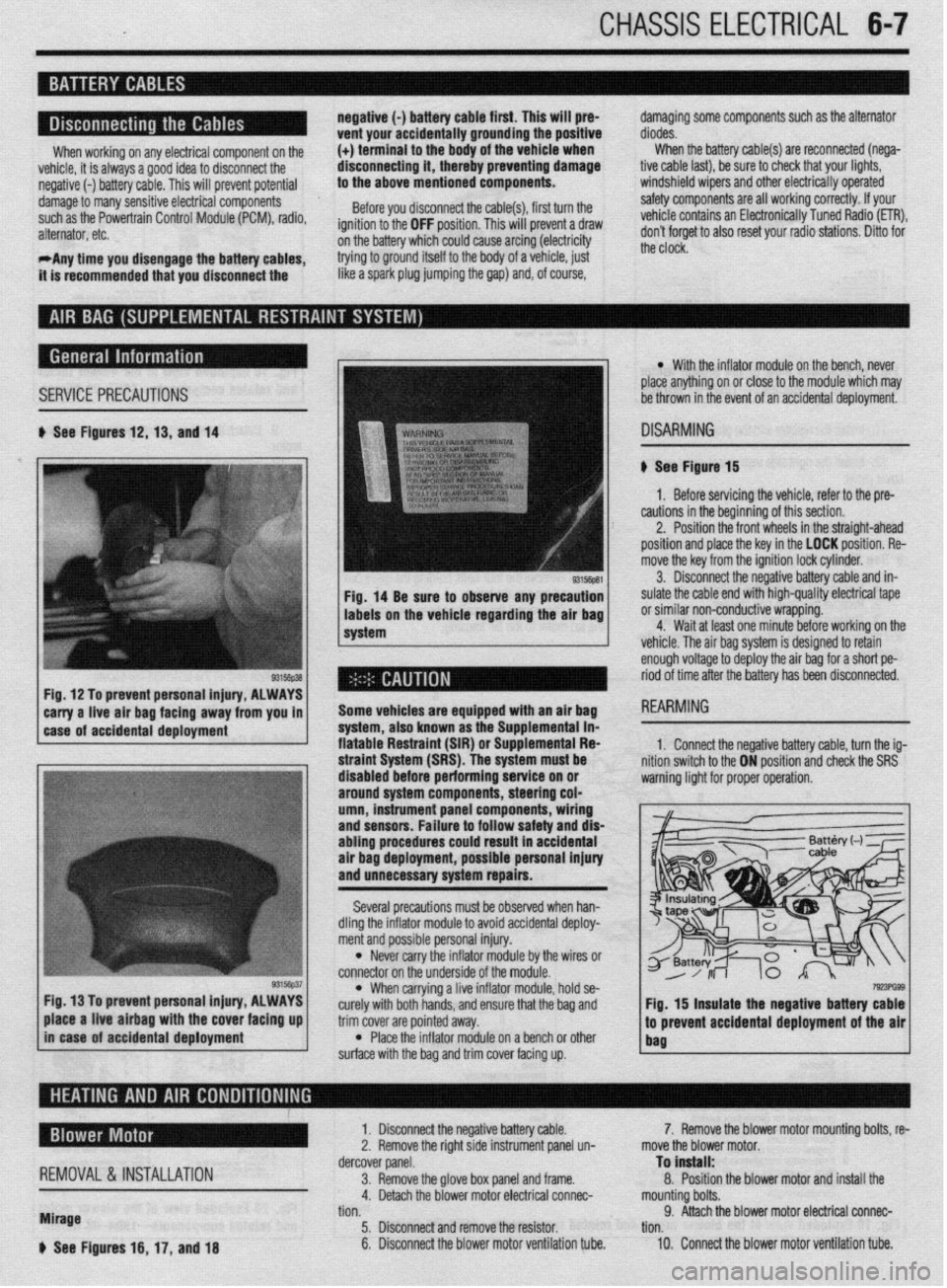
b See Figures 12,13, and 14
Fig, 14 Be sure to observe any precaution
labels on the vehicle regarding the air bag
system
Fig. 12 To prevent personal injury, ALWAYS
*
carry a-live -ah bag fac!ng away from you in 1
1 case of accidental deployment Some vehicles are equipped wtth an air bag
-.-‘--
syr1em, aiscl Known as I11 -I-- ‘------- -- sLe Supplemental in- fiatable Restraint (SIR) o r Suouiementai Fiea
l With the inflator module on the bench, never
place anything on or close to the module which may
be thrown in the event of an accidental deployment.
DISARMING
# See Figure 15
1. Before servicing the vehicle, refer to the pre-
cautions in the beginning of this section.
2. Position the front wheels in the straight-ahead
position and place the key in the LOCK position. Re-
move the key from the ignition lock cylinder.
3. Disconnect the negative battery cable and in-
sulate the cable end with high-quality electrical tape
or similar non-conductive wrapping.
4. Wait at least one minute before working on the
vehicle. The air baa svstem is desianed to retain
enough voltage to deploy the air bag for a short pe-
riod of time after the battery has been disconnected.
1. Connect the neoative batters cable. turn the ia-
3, hold se-
e bag and
trim cover are pointed away.
l Place the inflator module on a bench or other
surface with the bag and trim cover facing up.
7!r!3PG93 Fig. 15 insulate the negative battery cable
.I
to prevent accidental deployment of the air
bag place a live airbag with the cover facing up
in case of accidental deployment
REMOVAL &INSTALLATION
Mirage
b See Figures 16, 17, and 18 1. Disconnect the negative battery cable.
2. Remove the right side instrument panel un-
dercover panel.
3. Remove the glove box panel and frame.
4. Detach the blower motor electrical connec-
tion.
5. Disconnect and remove the resistor.
6. Disconnect the blower motor ventilation tube. 7. Remove the blower motor mounting bolts, re-
move the blower motor.
To install:
8. Position the blower motor and install the
mounting bolts.
9. Attach the blower motor electrical connec-
tion.
10. Connect the blower motor ventilation tube.
Page 254 of 408

1994-00 GALANT CHASSIS SCHEMATIC
_ TIMES HOT AT UL TIMES HOT AT
, FUSIBLE FUSISLE
LINK
‘6 LINK
1
4GA 101
I IGNITION
SWITCH
. ACCY
LOCK
w
a
FUSE
G
ID*
&i
2 E
GENERATOK -- COHBINAl
RELAY nETER
‘I
J!
d B
8
I
&
>
P
IC RECUATOR
DIAGRAM
33
. TIMES
Fl!SlELE
LINK
2
IGGA
ALTERNATOR
1
1994-00 GALANT CHASSIS SCHEMATIC
HOT AT UL TIMES HOT AT UL TIMES HOT AT ALL TIMES
Fusl8i.E FUSE
LINK J
e LA SGA
34 34
IGNITION
SWITCH
r-
4
s
4
1 a
CONDENSER ’
FAN IlOTOR
IQEUY (LO) ---.
.
d
CONDENSER
FAN
MOTOR
I ENGINE CONTROC
FIODLLE
I CONDENSER
FAN
HOTOll
RELAY
Gil)
DIAGRAM 34
Page 331 of 408
SUSPENSION AND STEERING 8-35
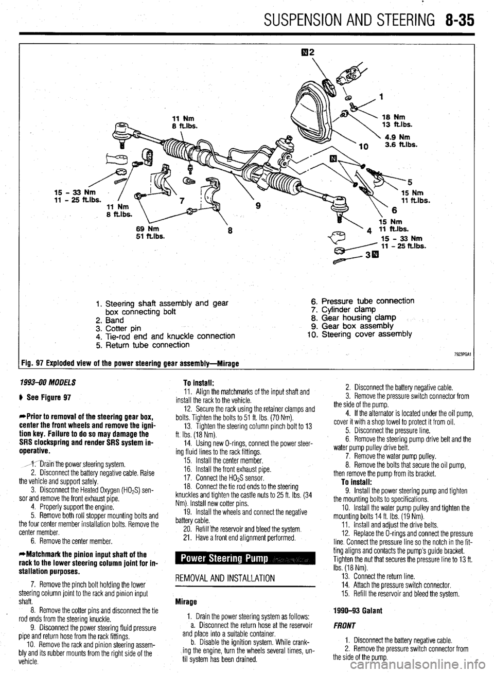
1. Steering shaft assembly and gear
box connecting bolt
2. Band
3. Cotter pin
4. Tie-rod end and knuckle connection
5. Return tube connection 6. Pressure tube connection
7. Cylinder clamp
8. Gear housing clamp
9. Gear box assembly 10. Steering cover assembly
7923PGAl FiD= 97 Exploded view of the power steering gear assembly-Mirage
1993-90 MODELS To install:
) See Figure 97
*Prior to removal of the steering gear box,
center the front wheels and remove the igni-
tion key. Failure to do so may damage the
SRS clockspring and render SRS system in-
operative.
,mr;iin thepower steering system.
2. Disconnect the battery negative cable. Raise
the vehicle and support safely.
3. Disconnect the Heated Oxygen (HOPS) sen-
sor and remove the front exhaust pipe.
4. Properly support the engine.
5. Remove both roll stopper mounting bolts and
the four center member installation bolts. Remove the
center member.
6. Remove the center member. 11. Align the matchmarks of the input shaft and
install the rack to the vehicle.
12. Secure the rack using the retainer clamps and
bolts. Tighten the bolts to 51 ft. Ibs. (70 Nm).
13. Tighten the steering column pinch bolt to 13
ft. Ibs. (18 Nm).
14. Using new O-rings, connect the power steer-
ing fluid lines to the rack fittings.
15. Install the center member.
16. Install the front exhaust pipe.
17. Connect the H02S sensor.
18. Connect the tie rod ends to the steering
knuckles and tighten the castle nuts to 25 ft. Ibs. (34
Nm). Install new cotter pins.
19. Install the wheels and connect the negative
battery cable.
20. Refill ‘the reservoir and bleed the system.
21. Have a front end alignment performed.
stallation purposes. -
7. Remove the pinch bolt holding the lower REMOVALANDINSTALLATION
steering column joint to the rack and pinion input
shaft.
8. Remove the cotter pins and disconnect the tie
rod ends from the steering knuckle.
9. Disconnect the power steering fluid pressure
pipe and return hose from the rack fittings.
IO. Remove the rack and pinion steering assem-
bly and its rubber mounts from the right side of the
vehicle. Mirage
1, Drain the power steering system as follows:
a. Disconnect the return hose at the reservoir
and place into a suitable container.
b. Disable the ignition system. While crank-
ing the engine, turn the wheels several times, un-
til system has been drained. 2. Disconnect the battery negative cable.
3. Remove the pressure switch connector from
the side of the pump.
4. If the alternator is located under the oil pump,
cover it with a shop towel to protect it from oil.
5. Disconnect the pressure line.
6. Remove the steering pump drive belt and the
water pump pulley drive belt.
7. Remove the water pump pulley.
8. Remove the bolts that secure the oil pump,
then remove the pump from its bracket.
To install: 9. Install the power steering pump and tighten
the mounting bolts to specifications.
IO. Install the water pump pulley and tighten the
mounting bolts 14 ft. Ibs. (19 Nm).
11. Install and adjust the drive belts.
12. Replace the O-rings and connect the pressure
line. Connect the pressure line so the notch in the fit-
ting aligns and contacts the pump’s guide bracket.
Tighten the nut that secures the pressure line to 13 ft.
Ibs. (18 Nm).
13. Connect the return line.
14. Attach the pressure switch connector.
15. Refill the reservoir and bleed the system.
1990-93 Galant
FRONT
1. Disconnect the battery negative cable.
2. Remove the pressure switch connector from
the side of the pump.
Page 332 of 408
8-36 SUSPENSION AND STEERING
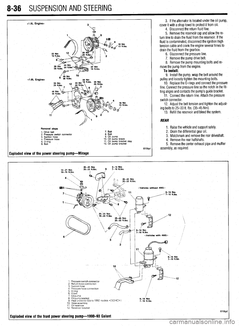
4 SL Engine>
<1.8L Engine>
Removal steps
1. Drive belt
7. BoIt
2. Pressure switch connector
8. Bolt
3. Suction hose
9. Oil pump
4. Pressure hose
10. Oil pump brace
2 Elrg
11. Oil pumo bracket stay
12. Oil pump bracket
93158gal
Exploded view of the power steering pump-Mirage
3. If the alternator is located under the oil pump,
cover it with a shop towel to protect it from oil.
4. Disconnect the return fluid line.
5. Remove the reservoir cap and allow the re-
turn line to drain the fluid from the reservoir. If the
fluid is contaminated, disconnect the ignition high
tension cable and crank the engine several times to
drain the fluid from the gearbox.
6. Disconnect the pressure line.
7. Remove the pump drive belt.
8. Remove the pump mounting bolts and re-
move the pump from the engine.
To install: 9. Install the pump, wrap the belt around the
pulley and loosely tighten the mounting bolts.
10. Replace the O-rings and connect the pressure
line. Connect the pressure line so the notch in the fit-
ting aligns and contacts the pump’s guide bracket.
1 I. Connect the return line. Attach the pressure
switch connector.
12. Adjust the belt tension and tighten the adjust-
ing bolts to 25-33 ft. Ibs. (35-45 Nm).
13. Refill the reservoir and bleed the system.
REAR
1. Raise the vehicle and support safely.
2. Drain the differential gear oil.
3. Matchmark and remove the rear driveshaft.
4. Remove the rear halfshafts.
5. Remove the center exhaust pipe and muffler
assembly, as required.
35-45 Nm 9-14 Nm
14-Z Nm 25-33 ft.lbs.
9 7-10 klbs.
2 g-lb Nm
7-10 ft.lbs.
Page 333 of 408
SUSPENSION AND STEERING 8-37
19-28 Nm
14-20 klbs.
/
12-18 Nm
9- 13 ft.lbs.
2rd
,
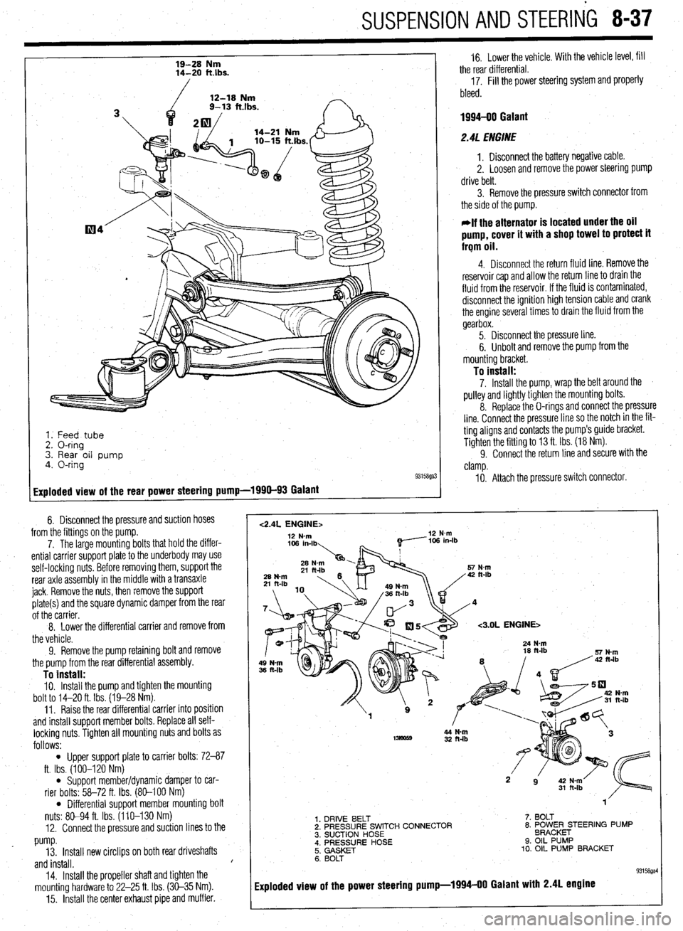
1. Feed tube
2. O-ring
3. Rear oil pump
4. O-ring
93158ga:
Exploded view of the rear power steering pump-1990-93 Galant
6. Disconnect the pressure and suction hoses
from the fittings on the pump.
7. The large mounting bolts that hold the differ-
ential carrier support plate to the underbody may use
self-locking nuts. Before removing them, support the
rear axle assembly in the middle with a transaxle
jack. Remove the nuts, then remove the support
plate(s) and the square dynamic damper from the rear
of the carrier.
8. Lower the differential carrier
and remove from
the vehicle.
9. Remove the pump retaining bolt and remove
the pump from the rear differential assembly.
To install: IO. Install the pump and tighten the mounting
bolt to 14-20 ft. Ibs. (19-28 Nm).
11. Raise the rear differential carrier into position
and install support member bolts. Replace all self-
locking nuts. Tighten all mounting nuts and bolts as
follows:
l Upper support plate to carrier bolts: 72-87
ft. Ibs. (100-120 Nm)
l Support member/dynamic damper to car-
rier bolts: 58-72 ft. Ibs. (80-100 Nm)
l Differential support member mounting bolt
nuts: 80-94 ft. Ibs. (110-130 Nm)
12. Connect the pressure and suction lines to the
pump.
13. Install new circlips on both rear driveshafts
and install. I
14.
Install the propeller shaft and tighten the
mounting hardware to 22-25 ft. Ibs. (30-35 Nm).
15. Install the center exhaust pipe and muffler.
1
16. Lower the vehicle. With the vehicle level, fill
the rear differential.
17. Fill the power steering system and properly
bleed.
1994-00 Galant
2.4L ENGINE
1. Disconnect the battery negative cable.
2. Loosen and remove the power steering pump
drive belt.
3. Remove the pressure switch connector from
the side of the pump.
*If the alternator is located under the oil
pump, cover it with a shop towel to protect it
frqm oil.
4. Disconnect the return fluid line. Remove the
reservoir cap and allow the return line to drain the
fluid from the reservoir. If the fluid is contaminated,
disconnect the ignition high tension cable and crank
the engine several times to drain the fluid from the
gearbox.
5. Disconnect the pressure line.
6. Unbolt and remove the pump from the
mounting bracket.
To install: 7. Install the pump, wrap the belt around the
pulley and lightly tighten the mounting bolts.
8. Replace the O-rings and connect the pressure
line. Connect the pressure line so the notch in the fit-
ting aligns and contacts the pump’s guide bracket.
Tighten the fitting to 13 ft. Ibs. (18 Nm).
9. Connect the return line and secure with the
clamp.
IO. Attach the pressure switch connector.
<2.4L ENGINE> 12 N-m 12 N-m
<3.OL ENGINE>
32 ft-lb
1. DRIVE BELT
2. PRESSURE SWITCH CONNECTOR
3. SUCTION HOSE
; i’;;‘;;RE HOSE 7. BOLT
8. ~O~~~E;TEER’NG PUMP
9. OIL PUMP
10. OIL PUMP BRACKET
6. BOLT
93158gal
Exploded view of the power steering pump-1994-00 Galant with 2.4L engine
Page 334 of 408
- 8-38 SUSPENSION AND STEERING
11. Adjust the power steering belt for proper ten-
sion and tighten the adjusting bolts.
12. Reconnect the negative battery cable.
13. Refill the reservoir and bleed the system.
3. Of EIJGINE
1. Disconnect the battery negative cable. 2. Disconnect the return fluid line. Remove the
reservoir cap and allow the return line to drain the
fluid from the reservoir. If the fluid is contaminated,
disconnect the ignition high tension cable and crank
the engine several times to drain the fluid from the
gear box.
3. Remove the power steering pump drive belt.
4. Remove the pressure switch connector from
the side of the pump.
5. If the alternator is located under the oil pump,
cover it with a shop towel to protect it from oil.
6. Disconnect the high pressure hose and the
return hose from the pump.
7. Remove the pump drive belt and unbolt the
pump from its bracket and remove the pump.
To install: 8. Install the pump, *rap the belt around the
pulley and tighten the bolts that secure the pump to
17 ft. Ibs. (24 Nm).
9. Replace the O-rings and connect the high
pressure hose. Connect the pressure line so the
notch in the fitting aligns and contacts the pump’s
guide bracket. Tighten the mounting nut with lock-
washer to 17 ft. Ibs. (24 Nm).
IO. Using a new hose clamp, connect the return
line.
11. Attach the pressure switch connector.
12. Adjust the belt tension and tighten the
adjust- ing bolts.
13. Refill the reservoir and bleed the system.
Diamante *
FRONT
. 1. Disconnect the battery negative cable. 2. Disconnect the return fluid line. Remove the
reservoir cap and allow the return line to drain the
fluid from the reservoir. If the fluid is contaminated,
disconnect the ignition high tension cable and crank
the engine several times to drain the fluid from the
gearbox.
3. Remove the power steering pump drive belt.
4. Remove the pressure switch connector from
the side of the pump.
5. If the alternator is located under the oil pump,
cover it with a shop towel to protect it from oil.
6. Disconnect the high pressure hose and the
return hose from the pump.
7. Remove the pump drive belt and unbolt the
pump from its bracket and remove the pump.
To install: 8. Install the pump, wrap the belt around the
pulley and tighten the bolts that secure the pump to
17 ft. Ibs. (24 Nm).
9. Replace the O-rings and connect the high
pressure hose. Connect the pressure line so the
notch in the fitting aligns and contacts the pump’s
guide bracket. Tighten the mounting nut with lock-
washer to 17 ft. Ibs. (24 Nm).
10. Using a new hose clamp, connect the return
line.
Il. Attach the pressure switch connector.
12. Adjust the belt tension and tighten the adjust-
ing bolts.
13. Refill the reservoir and bleed the system.
REAR
1. Disconnect the negative battery cable.
2. Drain the power steering fluid.
3. Remove the rear power steering pump heat
protector, located on the engine side of the differen-
tial on the transaxle.
4. Disconnect the pressure line from the pump.
5. Disconnect the suction hose from the pump.
6. Remove the mounting bolts and remove the
pump from the transaxle.
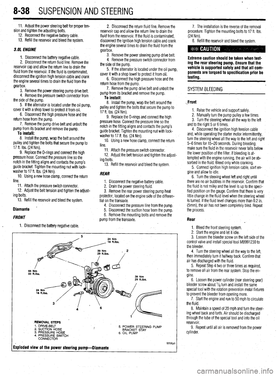
44
33
REMOVAL STEPS
5. POWER STEERING PUMP
BRACKET STAY
6. OIL PUMP 1. DRIVE-BELT
2. SUCTION HOSE I ’ 3. PRESSURE HOSE
4. PRESSURE SWITCH
CONNECTOR
Exploded view of the power steering pump-Diamante
. 93158ga5
7. The installation is the reverse of the removal
procedure. Tighten the mounting bolts to 17 ft. Ibs.
(24 Nm).
8. Refill the reservoir and bleed the system.
Extreme caution should be taken when test-
ing the rear steering pump. Ensure that the
vehicle is supported safely and that all com-
ponents are torqued to specification prior be
testing.
. SYSTEM BLEEDING
,Front
1. Raise the vehicle and support safely.
2. Manually turn the pump pulley a few times.
3. Turn the steering wheel all the way to the left
and to the right 5 or 6 times.
4. Disconnect the ignition high tension cable
and, while operating the starter motor intermittently,
turn the steering wheel all the way to the letI and right
5-6 times for 15-20 seconds. During bleeding,
make sure the fluid in the reservoir never falls below
the lower position of the filter. If bleeding is at-
tempted with the engine running, the air will be ab-
sorbed in the fluid. Bleed only while cranking.
5. Connect ignition high tension cable, start en-
gine and allow to idle.
6. Turn the steering wheel left and right until
there are no air bubbles in the reservoir. Confirm that
the fluid is not milky and the level is up to the speci-
fied position on the gauge. Confirm that there is very
little change in the fluid level when the steering wheel
is turned. If the fluid level changes more than 0.2 in.
(5mm), the air has not been completely bled. Repeat
the process.
Rear
.
1. Bleed the front steering system.
2. Start the engine and let it idle.
3. Loosen the bleeder screw on the left side of the
control valve and install special tool MB991230 to
the bleeder.
4. Turn the steering wheel all the way to the left,
then immediately turn it halfway back. Confirm that
air has discharged with the fluid.
5. Repeat Step 4 two or three times as required,
to remove all air from the rear system. Stop the en-
gine.
6. Loosen the power cylinder (rear steering gear)
bleeder screw about I/* turn and install the same
special tool with the rotation prevention metal fixtures
to prevent the bleeder from opening more.
7. Start the engine and run to 50 mph to circulate
the fluid.
8. Maintain a speed of 20 mph and turn the steer-
ing wheel back and forth. Air should be discharged ,
through the tube of the special tool and into the oil
reservoir.
9. Repeat until all air is removed from the power
cylinder.