alternator MITSUBISHI DIAMANTE 1900 User Guide
[x] Cancel search | Manufacturer: MITSUBISHI, Model Year: 1900, Model line: DIAMANTE, Model: MITSUBISHI DIAMANTE 1900Pages: 408, PDF Size: 71.03 MB
Page 77 of 408
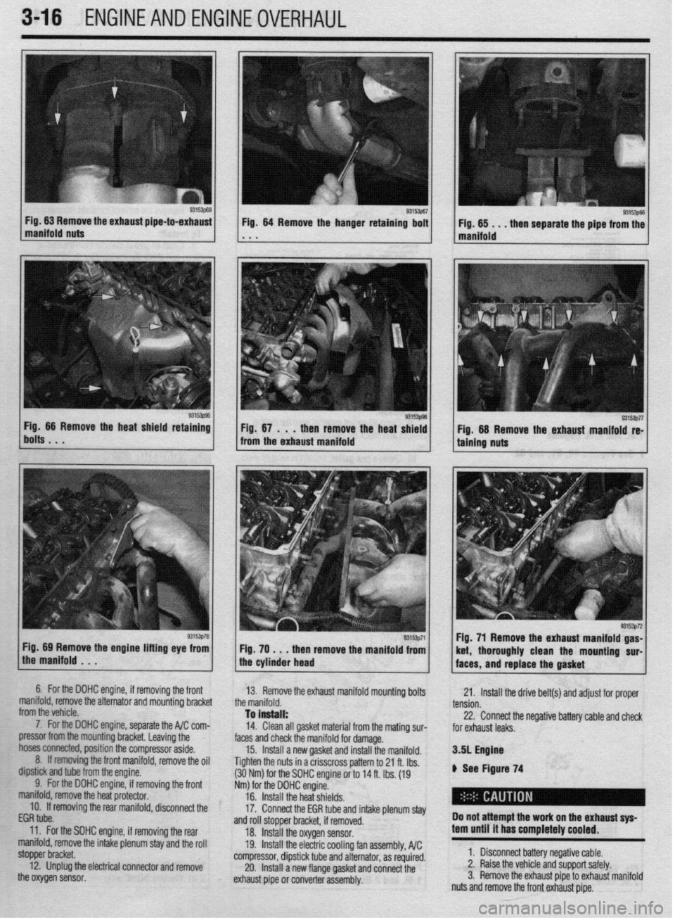
3-16 ,ENGlNEANDENGlNEOVERHAUL
Fig 66 Remove the heat shield retaining
bolts. . . g3’~‘51 Fig. 64 Remove the hanger retaining bolt
* . I(
Fig, 67 . . .
then remove the heat shield
from the exhaust manifold
Fig. 69 Remove the engine lifting eye from
the manifold . . . Fig. 70 , . . then remove the manifold from
the cylinder head Fig. 71 Remove the exhaust manifold gas-
/ faces, and replace the gasket ’ 93’53p72 ket, thoroughly clean the mountmg sur-
6. For the DOHC engine, if removing thr
a front
manifold, remove the alternator and mountin!
from the vehicle. 3 bracket
7. For the DOHC engine, separate the I$,, I.vIII- /r nnm
pressor from the mounting bracket. Leaving the
hoses ~~~, position the compressor aside,
8. ff removing the front manifold, remove the oil
dipstick and tube from the engine.
9. For the DOHC engine, if removing the front
manifold, remove the heat protector. 13. Remove the exhaust manifold mounting bolts
the manifold.
To install:
-4” PI,*, -11 rm.A.^L -,‘&^-:-I f-e.- IL- -_-I!-- - .-
17. lrlMll dll yWK1 Illdlell~l 110111 LIle lKWi~ SIN- faces and check the manifold for damage.
15. Install a new gasket and install the manifold.
Tighten the nuts in a crisscross pattern to 21 ft. Ibs.
(30Nm). .’ --.._
Nm) for 1
16. II 21. Install the drive belt(s) and adjust for proper
tension.
to1 the SOHC engine or to 14 ft. Ibs. (19
he DOHC engine.
Wall the heat shields. 22. Connect the negative battery cable and check
I- L- L, #
ror exnausr leaks.
3.51 Engfne
A Sam Finnwn 74
17. c
“IIII”“IUI” L”ll L”“““ll” IIIlu#lb p,““l~,aa~
and roll stopper bracket, if removed.
18. Install the oxygen sensor.
19. Install the electric cooling fan assembly, A/C
compressor, dipstick tube and alternator, as required.
20. Install a new flange gasket and connect the
exhaust pipe or converter assembly. Do not attempt the work on the
exhaust sys-
tern until it has completely coo
led.
1. Disconnect battery negative cable.
2. Raise the vehicle and support safely.
3. Remove the exhaust pipe to exhaust manifold
nuts and remove the front exhaust pipe. IO. If removing the rear manifold, disconnect the
EGR tube.
11. For the SOHC engine, if removing the rear
manifold, remove the intake plenum stay and the roll
stopper bracket.
12. Unplug the electrical connector and remove
the oxygen sensor.
Page 81 of 408
.
3-20 ENGINEANDENGINEOVERHAUL
Never open, service or drain the radiator or
cooling system when hot; serious burns can
occur from the steam and hot coolant. Also,
when draining engine coolant, keep in mind
that cats and dogs are attracted to ethylene
glycol antifreeze and could drink any that is
left in an uncovered container or in puddles
on the ground. This will prove fatal in suffi-
cient quantities. Always drain coolant into a
sealable container. Coolant should be reused
unless it is contaminated or is several years
old.
3. Remove the overflow hose and disconnect
the upper radiator hose.
*It is recommended that each clamp be
matchmarked to the hose. Observe the marks
and reinstall the clamps exactly when rein-
stalling the radiator.
4. If equipped with an automatic transaxle, re-
move and plug the fluid cooler hoses.
5. Unplug the electrical connector(s) from the
coolant fan motor.
6. Remove the mounting bolts, then remove the
fan and shroud assembly from the vehicle.
7. Remove the fan blade retainer nut from the
shaft on the fan motor and separate the fan from the
motor.
8. Remove the motor to shroud attaching
screws and the motor from the shroud.
To tnstall: 9. Install the motor to the shroud and secure
with the mounting bolts.
10. Install the remaining components in the re-
verse order of removal.
11. Fill the coohng system. Connect the negative
battery cable and check the cooling fan for proper op-
eration.
Diamante
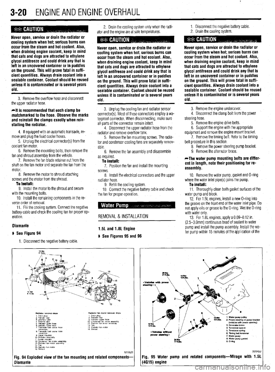
# See Figure 94
1. Disconnect the negative battery cable 2. Drain the cooling system only when the radi-
ator and the engine are at safe temperatures. 1. Disconnect the negative battery cable
2. Drain the cooling system.
Never open, service or drain the radiator or
cooling system when hot; serious burns can
occur from the steam and hot coolant. Also,
when draining engine coolant, keep in mind
that cats and dogs are attracted to ethylene
glycol antifreeze and could drink any that is
left in an uncovered container or in puddles
on the ground. This will prove fatal in suffi-
cient quantities. Always drain coolant into a
sealable container. Coolant should be reused
unless it is contaminated or is several years
old.
3. Unplug the cooling fan and radiator sensor
connector(s). Most of these connectors employ a wa-
terproof connector. When disconnecting, make sure
all parts of the connector remain intact.
4. Disconnect the upper radiator hose from the
radiator and remove overflow tank.
5. Remove the fan mounting screws. The radia-
tor and condenser cooling fans are separately remov-
able.
6. Remove the fan assembly and disassemble
Never open, service or drain the radiator or
cooling system when hot; serious burns can
occur from the steam and hot coolant. Also,
when draining engine coolant, keep in mind
that cats and dogs are attracted to ethylene
glycol antifreeze and could drink any that is
left in an uncovered container or in puddles
on the ground. This will prove fatal in suffi-
cient quantities. Always drain coolant into a
sealable container. Coolant should be reused
unless it is contaminated or is several years
old.
3. Remove the engine undercover.
4 Disconnect the clamp bolt from the power
steering hose.
5. Remove the engine drive belts.
6. Support the engine with the appropriate
equipment and remove the engine mount bracket.
7. Remove the timing belt Reier to the timing
belt procedure in this section
8 Remove the power steering pump bracket.
9. Remove the alternator brace.
as required.
To install: 7. Posrtion the fan and install the mounting
screws
*The water pump mounting bolts are differ-
ent in length, note their positioning for re-
assembly.
8 Install the electrical connectors and the upper
radiator hose.
9. Refill the cooling system.
IO. Connect the negative battery cable and check
the fan for orooer ooeration. 10. Remove the water pump, gasket and O-ring
where the water inlet pipe(s) joins the pump.
To install: 11, Thoroughly clean both gasket surfaces of the
water oumo and block.
12. For 1.5L engines, install a new O-ring into
the groove on the front end of the water inlet pipe. Do
not apply oils or grease to the O-ring. Wet the O-ring
with water only
13. For 1.8L engines, apply a 0.09-0.12 in.
(2.5-3 Omm) continuous bead of sealant to water
pump and rnstall the pump assembly. Install the wa-
ter pump within 15 minutes of the applrcation of the
REMOVAL & INSTALLATION
1.5L and 1.8L Engine
) See Figures 95 and 98
7923PGO :ig. 94 Exploded view of the fan mounting and related components- Fig. 95 Water pump and related components-Mirage with 1.51
liamante (4615) engine
Page 82 of 408
ENGINEANDENGINEOVERHAUL 3-21
7923PG08
ealant. Wait 1 hour after installation of the water
pump to refill the cooling system or start the engine.
14. Install the gasket and pump assembly and
tighten the bolts to 17 ft. Ibs. (24 Nm). Use care when
aligning the water pump with the water inlet pipe.
15. Install the remaining components in the re-
verse order of removal.
16. Fill the system with coolant. 17. Connect the negative battery cable, run the
vehicle until the thermostat opens and fill the radiator
completely.
18. Once the vehicle has cooled, recheck the
coolant level.
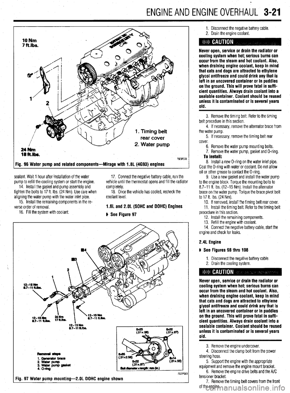
1.6L and 2.OL (SOHC and OOHC) Engines
+ See Figure 97
Fig
1. Disconnect the negative battery cable.
2. Drain the engine coolant.
Never open, service or drain the radiator or
cooling system when hot; serious burns can
occur from the steam and hot coolant. Also,
when draining engine coolant, keep in mind
that cats and dogs are attracted to ethylene
glycol antifreeze and could drink any that is
left in an uncovered container or in puddles
on the ground. This will prove fatal in suffi-
cient quantities. Always drain coolant into a
sealable container. Coolant should be reused
unless it is contaminated or is several years
old.
3. Remove the timing belt. Refer to the timing
belt procedure in this section.
4. If necessary, remove the alternator brace from
the water pump.
5. If necessary, remove the timing belt rear
cover.
6. Remove the water pump mounting bolts.
7. Remove the water pump, gasket and O-ring.
To Install: 8. Install a new O-ring on the water inlet pipe.
Coat the O-ring with water or coolant. Do not allow
oil or other grease to contact the O-ring.
9. Use a new gasket and install the water pump
to the engine block Torque the mounting bolts to
8.7-11 ft. Ibs. (12-15 Nm). Install the alternator
brace on the water pump. Torque the brace pivot bolt
to 17 ft. Ibs. (24 Nm).
10. If removed, install the timing belt rear cover.
11. Install the timing belt. Refer to the timing belt
procedure in this section.
12. Install the remaining components.
13. Refill the engine with coolant.
14. Connect the negative battery cable, start the
engine and check for leaks.
2.4L Engine
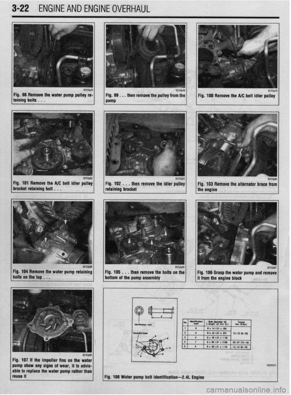
) See Figures 98 thru 108
1. Disconnect the negative battery cable
2. Drain the cooling system.
Never open, service or drain the radiator or
cooling system when hot; serious burns can
occur from the steam and hot coolant. Also,
when draining engine coolant, keep in mind
that cats and dogs are attracted to ethylene
glycol antifreeze and could drink any that is
left in an uncovered container or in puddles
on the ground. This will prove fatal in suffi-
cient quantities. Always drain coolant into a
sealable container. Coolant should be reused
unless it is contaminated or is several years
old.
3. Remove the engine undercover.
4. Disconnect the clamp bolt from the power
steering hose.
5 Support the engine with the appropriate
equipment and remove the engine mount bracket.
6. Remove the engine drive belts and the A/C
tensioner bracket.
7. Remove the timing belt covers from the front
of the engine.
Page 83 of 408
3-22 ENGINEANDENGINEOVERHAUL
Fig. 98 Remove the wafer pump pulley re-
taining bolts ~ . .
Fig 101 Remove the A/C beit idler pulley
braEketretainingboit..., g3’a/ 93153p30 Fig. 99 . . . then remove the pulley from the
pump
931531183 Fig. 102 . . * then remove the idler pulley
retaining bracket
Fig. 104 Remove the water pump retaining
Fig. lfJ5 . . . then remove the bolts on the
bolts on the top . . .
bottom of the pump assembly
Fig. 107 if the impeller fins on the water
able to replace the water pump rather than
reuse it Fig. 100 Remove the A/C belt idler pulley
g. 103 Remove the alternator brace from
Fig. 108 Water pump bolt identification-2.41 Engine
Page 84 of 408
ENGlNEANDENGlNEOVERHAiL 3-23
8. Remove the camshaft and silent shaft timing
belts. Refer to the timing belt procedure in this sec-
tion
9. Remove the A/C belt idler pulley and pulley
bracket.
10. Remove the alternator brace,
11. Remove the water pump, gasket and O-ring
where the water inlet pipe(s) joins the pump.
To install:
12. Thoroughly clean both gasket surfaces of the
water pump and block.
13. Install a new O-ring into the groove on the
front end of the water inlet pipe and wet with clean
antifreeze only. Do not apply oils or grease to the O-
ring.
14. Using a new gasket, install the water pump
assembly. Tighten bolts with the head mark 4 to 10
ft Ibs. (14 Nm) and bolts with the head mark 7 to 18
ft. Ibs. (24 Nm).
15. Install the A/C pulley and pulley bracket,
16. Install the timing belts. Refer to the timing
belt procedure in this section.
17. Install the engine drive belts.
18. Install the engine mount bracket.
19. Install the engine undercover,
20. Fill the system with coolant.
21. Connect the negative battery cable, run the
vehicle until the thermostat opens and fill the radiator
completely.
22. Once the vehicle has cooled, recheck the
coolant level.
3.OL and 3.5L Engines
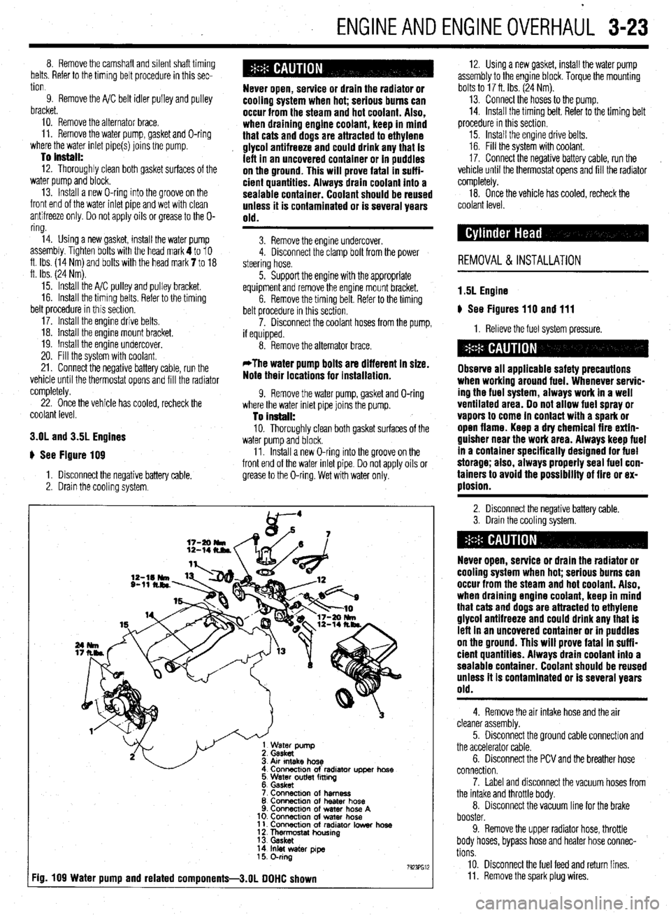
# See Figure 109
1. Disconnect the negative battery cable,
2. Drain the cooling system.
Never open, service or drain the radiator or
cooling system when hot; serious burns can
occur from the steam and hot coolant. Also,
when draining engine coolant, keep in mind
that cats and dogs are attracted to ethylene
glycol antifreeze and could drink any that is
left in an uncovered container or in puddles
on the ground. This will prove fatal in suffi-
cient quantities. Always drain coolant into a
sealable container. Coolant should be reused
unless it is contaminated or is several years
old.
3. Remove the engine undercover.
4. Disconnect the clamp bolt from the power
steering hose.
5. Support the engine with the appropriate
equipment and remove the engine mount bracket.
6. Remove the timing belt. Refer to the timing
belt procedure in this section.
7. Disconnect the coolant hoses from the pump,
if equipped.
8. Remove the alternator brace.
*The water pump bolts are different in size.
Note their locations for installation.
9. Remove the water pump, gasket and O-ring
where the water inlet pipe joins the pump.
To install: 10. Thoroughly clean both gasket surfaces of the
water pump and block.
11. Install a new O-ring into the groove on the
front end of the water inlet pipe. Do not apply oils or
grease to the O-ring. Wet with water only.
Atr Intake hose
Connactlon of’ radlator upper hose
5 Water outlet fming
6. Gasket
7 Connacmn of harness
8 Connection of heater hose
9. Connection of water hose A
10. ConnectIon of water hose
11. Connection of radiator Iowar hose
1 f Thn&ostat housing
14 Inlet water pye
15 O-ring
7923Fw :ig. 109 Water pump and related components-3.01 DOHC shown
12. Using a new gasket, install the water pump
assembly to the engine block. Torque the mounting
bolts to 17 ft. Ibs. (24 Nm).
13. Connect the hoses to the pump.
14. Install the timing belt. Refer to the timing belt
procedure in this section.
15. Install the engine drive belts.
16. Fill the system with coolant.
17. Connect the negative battery cable, run the
vehicle until the thermostat opens and fill the radiator
completely.
18. Once the vehicle has cooled, recheck the
coolant level.
REMOVAL & INSTALLATION
1.5L Engine
u See Figures 110 and 111
1. Relieve the fuel system pressure.
Observe all applicable safety precautions
when working around fuel. Whenever servic-
ing the fuel system, always work in a well
ventilated area. Do not allow fuel spray or
vapors to come in contact with a spark or
open flame. Keep a dry chemical fire extin-
guisher near the work area. Always keep fuel
in a container specifically designed for fuel
storage; also, always properly seal fuel con-
tainers to avoid the possibility of fire or ex-
plosion.
2. Disconnect the negative battery cable.
3. Drain the cooling system.
Never open, service or drain the radiator or
cooling system when hot; serious burns can
occur from the steam and hot coolant. Also,
when draining engine coolant, keep in mind
that cats and dogs are attracted to ethylene
glycol antifreeze and could drink any that is
left in an uncovered container or in puddles
on the ground. This will prove fatal in suffi-
cient quantities. Always drain coolant into a
sealable container. Coolant should be reused
unless it is contaminated or is several years
old.
4. Remove the air intake hose and the air
cleaner assembly.
5. Disconnect the ground cable connection and
the accelerator cable.
6. Disconnect the PCV and the breather hose
connection.
7. Label and disconnect the vacuum hoses from
the intake and throttle body.
8. Disconnect the vacuum line for the brake
booster.
9. Remove the upper radiator hose, throttle
body hoses, bypass hose and heater hose connec-
tions
10. Disconnect the fuel feed and return lines.
11. Remove the spark plug wires.
Page 90 of 408
ENGINEANDENGINEOVERHAUL 3-29
l HOzS sensor l ECT gauge sender l ECT sensor l MAP sensor l IAT sensor l TP sensor l IAC motor l injector harness l ignition coil l CMP sensor l EGR solenoid valve
33. Install the spark plug wires and cover,
34. Replace the O-rings and connect the fuel
lines.
35. Install the air cleaner and intake hose. Con-
nect the breather hose.
36. Fill the cooling system.
37. Connect the negative battery cable
3.01 DDHC Engine
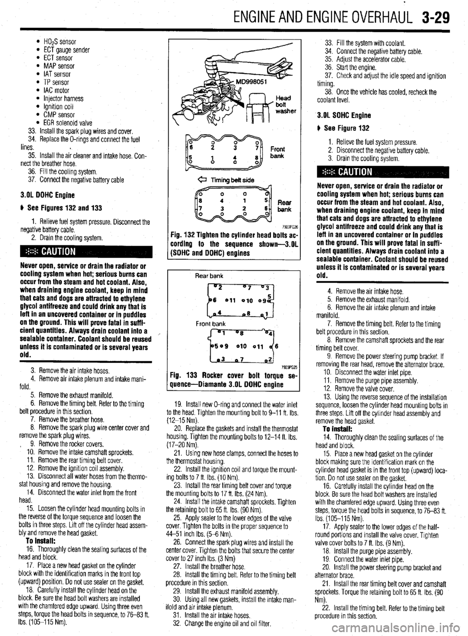
ti See Figures 132 and 133
1. Relieve fuel system pressure. Disconnect the
negative battery cable.
2. Drain the cooling system.
Never open, service or drain the radiator or
cooling system when hot; serious burns can
occur from the steam and hot coolant. Also,
when draining engine coolant, keep in mind
that cats and dogs are attracted to ethylene
glycol antifreeze and could drink any that is
left in an uncovered container or in puddles
on the ground. This will prove fatal in suffi-
cient quantltles. Always drain coolant into a
sealable container. Coolant should be reused
unless it is contaminated or is several years
old.
3. Remove the air intake hoses.
4. Remove air intake plenum and intake mani-
fold.
5. Remove the exhaust manifold.
6. Remove the timing belt. Refer to the timing
belt procedure in this section.
7. Remove the breather hose.
8. Remove the spark plug wire center cover and
remove the spark plug wires.
9. Remove the rocker covers.
10. Remove the intake camshaft sprockets.
11. Remove the rear timing belt cover.
12. Remove the ignition coil assembly.
13. Disconnect all water hoses from the thermo-
stat housing and remove the housing.
14. Disconnect the water inlet from the front
head.
15. Loosen the cylinder head mounting bolts in
the reverse of the torque sequence and loosen the
bolts in three steps. Lift off the cylinder head assem-
bly and remove the head gasket.
To install: 16. Thoroughly clean the sealing surfaces of the
head and block.
17. Place a new head gasket on the cylinder
block with the identification marks in the front top
(upward) position. Do not use sealer on the gasket,
18. Carefully install the cylinder head on the
block. Be sure the head bolt washers are installed
with the chamfered edge upward. Using three even
steps, torque the head bolts in sequence, to 76-83 ft.
Ibs. (105-115 Nm).
@ Timing belt side
7923PG26 :ig. 132 Tighten the cylinder head bolts ac-
:ording to the sequence shown-3.01
SDHC and DDHC) engines
Rear bank
[::od
04
~8 01
Front bank
'1 "8
509 010 011 6
1.03 07 02 7923ffi25 Fig. 133 Rocker cover bolt torque se-
quence-Diamante 3.OL DDHC engine
19. Install new O-ring and connect the water inlet
to the head. Tighten the mounting bolt to 9-11 ft. Ibs
(12-15 Nm).
20. Replace the gaskets and install the thermostat
housing. Tighten the mounting bolts to 12-14 ft. Ibs.
(17-20 Nm).
21. Using new hose clamps, connect the hoses to
the thermostat housing.
22. Install the Ignition coil and torque the mount-
ing bolts to 7 ft. Ibs. (10 Nm).
23. Install the rear timing belt cover and torque
the mounting bolts to 17 ft. Ibs. (24 Nm).
24. Install the intake camshaft sprockets. Tighten
the retaining bolt to 65 ft. Ibs. (90 Nm).
25. Apply sealer to the lower edges of the valve
cover. Tighten the bolts in the proper sequence to
44-51 inch Ibs. (5-6 Nm).
26. Connect the spark plug wires and install the
center cover. Tighten the bolts that secure the center
cover to 27 inch Ibs. (3 Nm)
27. Install the breather hose.
28. Install the timing belt. Refer to the timing belt
procedure in this section,
29. Install the exhaust manifold assembly.
30. Using all new gaskets, install the intake man-
ifold and air intake plenum.
31. Install the air intake hoses.
32. Change the engine oil and oil filter. 33. Fill the system wrth coolant.
34. Connect the negabve battery cable.
35. Adjust the accelerator cable.
36. Start the engine.
37. Check and adjust the idle speed and ignition
timing.
38. Once the vehicle has cooled, recheck the
coolant level.
3.OL SDHC Engine
# See Figure 132
1. Relieve the fuel system pressure.
2. Disconnect the negative battery cable.
3. Drain the cooling system.
Never open, service or drain the radiator or
cooling system when hot; serious burns can
occur from the steam and hot coolant. Also,
when draining engine coolant, keep in mind
that cats and dogs are attracted to ethylene
alvcol antifreeze and could drink any that is
Left in an uncovered container or in puddles
on the ground. This will Drove fatal in suff i-
cient quantities. Always drain coolant into a
sealable container. Coolant should be reused
Unless it is Contaminated or is several years
old.
4. Remove the air intake hose.
5. Remove the exhaust manifold.
6. Remove the air intake plenum and intake
manifold.
7. Remove the timing belt. Refer to the timing
belt procedure in this section.
8. Remove the camshaft sprockets and the rear
timing belt cover.
9. Remove the power steering pump bracket. If
removing the rear head, remove the alternator brace.
10. Disconnect the water inlet pipe.
11. Remove the purge pipe assembly.
12. Remove the valve cover,
13. Using the reverse sequence of the installation
sequence, loosen the cylinder head mounting bolts in
three steps. Lift off the cylmder head assembly and
remove the head gasket.
To install: 14. Thoroughly clean the sealing surfaces of the
head and block.
15. Place a new head gasket on the cylinder
block making sure the identification mark on the
cylrnder head gasket is in the front top (upward) loca-
tion. Do not use sealer on the gasket,
16. Carefully install the cylinder head on the
block. Be sure the head bolt washers are installed
with the chamfered edge upward. Using three even
steps, torque the head bolts in sequence, to 7683 ft.
Ibs. (105-115 Nm).
17. Apply sealer to the lower edges of the half-
round portions and install the valve cover. Tighten
valve cover bolts to 7 ft. Ibs. (9 Nm).
18. Install the purge pipe assembly.
19. Connect the water inlet pipe.
20. Install the power steering pump bracket and
alternator brace.
21. Install the rear timing belt cover and camshaft
sprockets. Torque the retaining bolt to 65 ft. Ibs. (90
Nm).
22. Install the timing belt. Refer to the timing belt
procedure in this section.
Page 101 of 408
l
3-40 ENGINEANDENGINEOVERHAUL
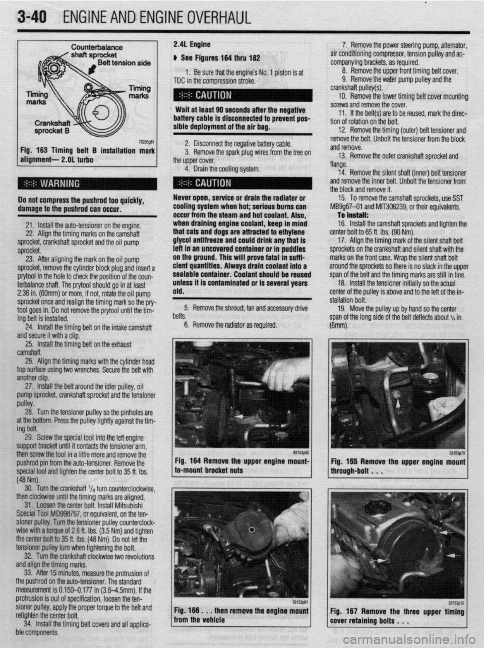
Counterbaiance
19235861
Fig. 163 Timing belt 5 installation mark
alignment- 2.OL turbo
Do not compress the pushrod too quickly,
damage to the pushrod can occur.
21. Install the auto-tensioner on the engine.
22. Align the timing marks on the camshaft
sprocket, crankshaft sprocket and the oil pump
sprocket.
23. After aligning the mark on the oil pump
: sprocket, remove the cylinder block plug and insert a
prytool in the hole to check the position of the coun-
terbalance shaft. The orvtool should ao in at least 7. Remove the power steering pump, alternator
air conditioning compressor, tension pulley and ac-
companying brackets, as required.
8 Remove the upper front timing belt cover.
9. Remove the water pump pulley and the
crankshaft pulley(s).
10. Remove the lower timing belt cover mountinf
screws and remove the cover.
11. If the belt(s) are to be reused, mark the direc.
tion of rotation on the belt.
12. Remove the timing (outer) belt tensioner and
remove the belt. Unbolt the tensioner from the block
and remove.
13. Remove the outer crankshaft sprocket and
flange.
14. Remove the silent shaft (inner) belt tensioner
and remove the inner belt. Unbolt the tensioner from
the block and remove it.
15. To remove the camshaft sprockets, use SST
Ml39g67-01 and MlT308239, or their equivalents.
To in!3tall:
16. Install the camshaft sprockets and tighten thr
center bolt to 65 ft. Ibs. (90 Nm).
17. Align the timing mark of the silent shaft belt
sprockets on the crankshaft and silent shaft with the
marks on the front case. Wrap the silent shaft belt
around the sprockets so there is no slack in the uppe
!
I span of the belt and the timing marks are still in line.
18. Install the tensioner initially so the actual
:enter of the pulley is above and to the left of the in-
jtallation bolt. 2.36 in. (60mm) or more, if not, rotai;! the oil pump
sprocket once and realign the timing mark so the pry-
24. Install the timing belt on the intake camshaft
and secure it with a clip. .
25. Install the timina belt on the exhaust old. 2.41 Engine
I: # See Figures 164 thru 162
1. Be sure that the engine’s No. 1 piston is at
TDC in the compression stroke.
Wait at least 90 seconds after the negative
battery cable is disconnected to prevent pos-
sible deployment of the air bag.
2. Disconnect the negative battery cable.
3. Remove the spark plug wires from the tree on
the upper cover.
4. Drain the cooling system.
Never open, service or drain the radiator or
cooling system when hot; serious bums can
occur from the steam and hot coolant. Also,
when draining engine coolant, keep in mind
that cats and dogs are attracted to ethylene
glycol antifreeze and could drink any that is
left in an uncovered container or in puddles
on the ground. This will prove fatal in suffi-
cient quantities. Always dram coolant into a
sealable container. Coolant should be reused
unless it is contaminated or is several years
tool goes in. Do not remove the on/ool until the tfrn- 5. Remove the shroud, fan and accessory drive
ing belt is installed. lelts.
6. Remove the radiator as required. 19. Move the pulley up by hand so the center
jpan of the lona side of the belt deflects about 11~ in.
camshaft.
26. Align the timing marks with the cylinder head
top surface using two wrenches. Secure the belt with
another clip.
27. tnstatf the belt around the idler pulley, oil
pump sprocket, crankshaft sprocket and the tensioner
pulley.
28. Turn the tensioner pulley so the pinholes are
at the bottom. Press the pulley lightly against the tim-
ing belt.
29. Screw the special tool into the left engine
support bracket until it contacts the tensioner arm,
then screw the tool in a little more and remove the
pushrod pin from the auto-tensioner. Remove the
special tool and tighten the center bolt to 35 ft. Ibs.
(48 Nm). Fig 164 Remove the upper engine mount-
to-mount bracket nuts al%@]
Pm3p70 Fig. 165 Remove the upper engine mount
through-bolt . . .
30. Turn the crankshaft ‘Id turn counterclockwise,
then clockwise until the timing marks are aligned.
31. Loosen the center bolt. Install Mitsubishi
Special Tool MD998767, or equivalent, on the ten-
sioner p&y. Turn the tensioner pulley counterclock-
wise with a torque of 2.6 ft. Ibs. (3.5 Nm) and tighten
the center boftto 35 ft. tbs. (48 Nm). Do not let the
tensioner pUtFey turn when tightening the bolt.
32. Turn the crankshaft clockwise two revolutions
and align the timing marks.
33. After 15 minutes, measure the protrusion of
the pushrod on the auto-tensioner. The standard
measurement is 0.150-0.177 in (3.8-4.5mm). If the
I protrusion is out of specification, loosen the ten-
I sioner pulley, apply the proper torque to the belt and
: retighten the center bolt.
34. Install the timing belt covers and all applica-
i ble components.
Page 103 of 408
.
3-42 ENGINEANDENGINEOVERHAUL
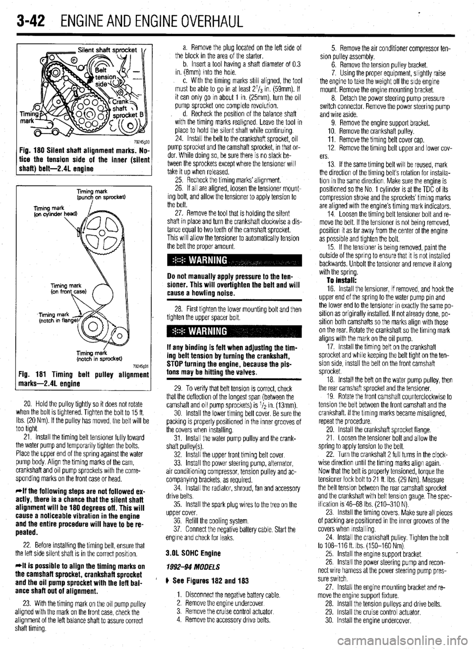
Fig. 180 Silent shaft alignment marks. No,
tice the tension side of the inner (silen
shaft) belt-2.41 enaine
Timing merk
(pun+ on sprocket)
liming m&k
(notch in sprocket)
79245g31 :ig. 181 Timing belt pulley alignmenl
narks-2.41 enoine
20. Hold the pulley tightly so it does not rotate
when the bolt is tlghtened. Tighten the bolt to 15 ft.
Ibs. (20 Nm). If the pulley has moved, the belt will be
too tight
21. Install the timing belt tensioner fully toward
the water pump and temporarily tighten the bolts.
Place the upper end of the spring against the water
pump body. Align the timing marks of the cam,
crankshaft and oil pump sprockets with the corre-
sponding marks on the front case or head.
*If the following steps are not followed ex-
actly, there is a chance that the silent shaft
alignment will be 180 degrees off. This will
cause a noticeable vibration in the engine
and the entire procedure will have to be re-
peated.
22. Before installing the timing belt, ensure that
the left side silent shaft is in the correct position.
*It is possible to align the timing marks on
the camshaft sprocket, crankshaft sprocket
and the oil pump sprocket with the lefl bal-
ance shaft out of alignment.
23. With the timing mark on the oil pump pulley
aligned with the mark on the front case, check the
alignment of the left balance shaft to assure correct
shaft timing. a. Remove the plug located on the left side of
the block in the area of the starter.
b. Insert a tool having a shaft diameter of 0.3
in. (8mm) into the hole.
c. With the timing marks still aligned, the tool
must be able to go in at least 2l/s in. (59mm). If
it can only go m about 1 in. (25mm), turn the oil
pump sprocket one complete revolution.
d. Recheck the position of the balance shaft
with the timing marks reahgned. Leave the tool in
place to hold the silent shaft while continuing.
24. Install the belt to the crankshaft sprocket, oil
pump sprocket and the camshaft sprocket, in that or-
der. While doing so, be sure there is no slack be-
tween the sprockets except where the tensioner will
take it up when released.
25. Recheck the timing marks’ alignment.
26. If all are aligned, loosen the tensioner mount-
ing bolt, and allow the tensioner to apply tension to
the belt.
27. Remove the tool that is holding the silent
shaft in place and turn the crankshaft clockwise a dis-
tance equal to two teeth of the camshaft sprocket.
This will allow the tensioner to automatically tension
the belt the proper amount.
Do not manually apply pressure to the ten-
sioner. This will overtighten the belt and will
cause a howling noise.
28. First tighten the lower mounting bolt and then
tighten the upper spacer bolt.
If any binding is felt when adiustino the tim-
ing delt tension by turning th;! crankshaft,
STOP turning the engine, because the pis-
tons may be hitting the valves.
29. To verify that belt tension is correct, check
that the deflection of the longest span (between the
camshaft and oil pump sprockets) is I/* in. (13mm).
30. Install the lower timing belt cover. Be sure the
packing is properly positioned in the inner grooves of
the covers when installing.
31. Install the water pump pulley and the crank-
shaft pulley(s).
32. Install the upper front timing belt cover.
33. Install the power steering pump, alternator,
air conditioning compressor, tension pulley and ac-
companying brackets, as required.
34. Install the radiator, shroud, fan and accessory
drive belts.
35. Install the spark plug wires to the tree on the
upper cover.
36. Refill the cooling system.
37. Connect the negative battery cable. Start the
engme and check for leaks.
3.OL SDHC Engine
1992-94 MODELS
# See Figures 182 and 183
1. Disconnect the negative battery cable.
2. Remove the engine undercover
3. Remove the cruise control
actuator 4. Remove the accessory drive belts. 5. Remove the air conditioner compressor ten-
sion pulley assembly.
6. Remove the tension pulley bracket.
7. Using the proper equipment, slightly raise
the engine to take the weight off the side engine
mount. Remove the engine mounting bracket.
8. Detach the power steering pump pressure
switch connector. Remove the power steering pump
and wire aside.
9. Remove the engine support bracket.
10. Remove the crankshaft pulley.
11. Remove the timing belt cover cap.
12. Remove the timing belt upper and lower cov-
ers.
13. If the same timing belt will be reused, mark
the direction of the timing belt’s rotation for installa-
tion in the same direction. Make sure the engine is
positioned so the No. 1 cylinder is at the TDC of its
compression stroke and the sprockets’ timing marks
are aligned with the engine’s timing mark indicators.
14. Loosen the timing belt tensioner bolt and re-
move the belt. If the tensioner is not being removed,
position it as far away from the center of the engine
as possible and tighten the bolt.
15. If the tensioner is being removed, paint the
outside of the spring to ensure that it is not installed
backwards. Unbolt the tensioner and remove it along
with the spring.
To install:
16. Install the tensioner, if removed, and hook the
upper end of the spring to the water pump pin and
the lower end to the tensioner in exactly the same po-
sition as originally installed. If not already done, po-
sition both camshafts so the marks align with those
on the rear. Rotate the crankshaft so the timing mark
aligns with the mark on the oil pump.
17. Install the timing belt on the crankshaft
sprocket and while keeping the belt tight on the ten-
sion side, install the belt on the front camshaft
sprocket.
18. Install the belt on the water pump pulley, then
the rear camshaft sprocket and the tensioner.
19. Rotate the front camshaft counterclockwise to
tension the belt between the front camshaft and the
crankshaft. If the tlmlng marks became misaligned,
repeat the procedure.
20. Install the crankshaft sprocket flange.
21. Loosen the tensioner bolt and allow the
spring to apply tension to the belt.
22. Turn the crankshaft 2 full turns in the clock-
wise direction until the timing marks align again.
Now that the belt is properly tensioned, torque the
tensioner lock bolt to 21 ft. Ibs. (29 Nm). Measure
the belt tension between the rear camshaft sprocket
and the crankshaft with belt tension gauge, The spec-
ification is 46-68 Ibs. (210-310 N).
23. Install the timing covers. Make sure all pieces
of packing are positioned in the inner grooves of the
covers when Installing.
24. install the crankshaft pulley. Tighten the bolt
to 108-116ft. Ibs. (150-160 Nm)
25. Install the engine support bracket.
26. Install the power steering pump and recon-
nect wire harness at the power steering pump pres-
sure switch.
27. Install the engine mounting bracket and re-
move the engine support fixture.
28. Install the tension pulleys and drive belts.
29. Install the cruise control actuator.
30 Install the engine undercover.
Page 104 of 408

ENGINEANDENGINEOVERHAU'L 3-43
2. Bolt
3. Washer
4. Crankshaft pulley
5. Access cover
6. Right side upper
front cover
7. Cap
8. Left side upper front
OOVM 9. Front lower cover
10. Flange 90 Nm
65 ft.lbs.
I
16
1
r
11
I
26 Nm
19 ft.lbs.
11. Lookbolt
12. Tensioner
13. Tensbner spring
14. Timing bait
I 15. Crankshaft sprocket
16. Bott
155 Nm 17. Camshaft sprocket
112 ft.lbs. 18. Left slde rear cover
19. Right side rear cwer
:ig. 182 Exploded view of the timing belt covers, timing belt and related parts-1992-94 Mitsubishi 3.OL SOHC engine 91'251gb:
TIMING MARK
TIMING MARK ON ON BELT COVER
REAR COVER OR
ALTERNATOR BRACKET
CAMSHAFT SPROCKET
TIMINQ BELT TENSIONER
ON FRONT CASE
CRANKSHAFT SPROCKET
:ig. 183 Crankshaft and camshaft sprocket alignment for proper timing belt replacement-1992-94 Mitsubishi 3.OL SOHC engine
Page 105 of 408
.
3-44 ENGINEANDENGINEOVERHALJL
31. Connect the negative battery cable.
32. Road test the vehicle.
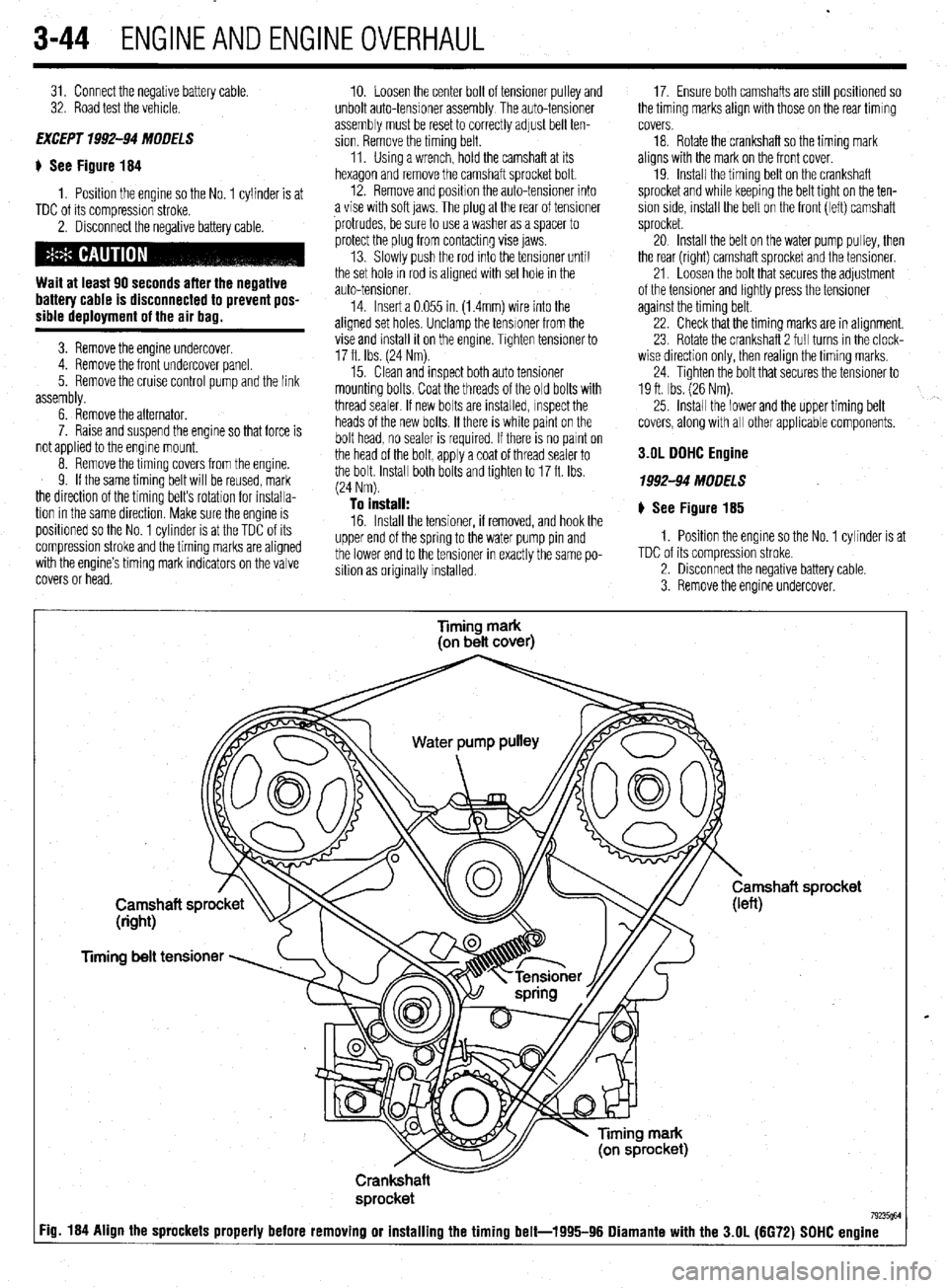
EXCEPT 1992-94 MODELS
$ See Figure 184
1. Position the engine so the No. 1 cylinder is at
TDC of its compression stroke.
2. Disconnect the negative battery cable.
Wait at least 90 seconds after the negative
battery cable is disconnected to prevent pos-
sible deployment of the air bag.
3. Remove the engine undercover.
4. Remove the front undercover panel.
5. Remove the cruise control pump and the link
assembly.
6. Remove the alternator.
7. Raise and suspend the engine so that force is
not applied to the engme mount,
8. Remove the timing covers from the engine.
9. If the same timing belt will be reused, mark
the direction of the timing belt’s rotation for installa-
tion in the same direction. Make sure the engine is
positroned so the No. 1 cylinder is at the TDC of its
compression stroke and the timing marks are aligned
with the engine’s timing mark indicators on the valve
covers or head. 10. Loosen the center bolt of tensioner pulley and
unbolt auto-tensioner assembly The auto-tensioner
assembly must be reset to correctly adjust belt ten-
sion. Remove the timing belt.
11. Using a wrench, hold the camshaft at its
hexagon and remove the camshaft sprocket bolt.
12. Remove and position the auto-tensioner into
a vise with soft jaws. The plug at the rear of tensioner
protrudes, be sure to use a washer as a spacer to
protect the plug from contacting vise jaws.
13. Slowly push the rod Into the tensioner until
the set hole rn rod is aligned with set hole in the
auto-tensioner.
14. Insert a 0.055 in. (1.4mm) wire into the
aligned set holes. Unclamp the tensioner from the
vise and install it on the engine. Trghten tensroner to
17 ft. Ibs. (24 Nm).
15. Clean and inspect both auto tensioner
mounting bolts. Coat the threads of the old bolts with
thread sealer. If new bolts are installed, Inspect the
heads of the new bolts. If there is white paint on the
bolt head, no sealer is required. If there is no parnt on
the head of the bolt, apply a coat of thread sealer to
the bolt. Install both bolts and tighten to 17 ft. Ibs.
(24 Nm).
To install: 16. Install the tensioner, if removed, and hook the
upper end of the spring to the water pump pin and
the lower end to the tensioner in exactly the same po-
sition as originally installed. 17. Ensure both camshafts are still positioned so
the timing marks align with those on the rear timing
covers.
18. Rotate the crankshaft so the timing mark
aligns with the mark on the front cover.
19. Install the timing belt on the crankshaft
sprocket and while keeping the belt tight on the ten-
sion side, mstall the belt on the front (left) camshaft
sprocket.
20 Install the belt on the water pump pulley, then
the rear (right) camshaft sprocket and the tensioner.
21. Loosen the bolt that secures the adjustment
of the tensioner and lightly press the tensioner
against the timing belt.
22. Check that the timing marks are in alignment.
23 Rotate the crankshaft 2 full turns in the clock-
wise direction only, then realign the timing marks,
24. Tighten the bolt that secures the tensioner to
19 ft. Ibs. (26 Nm).
25. install the lower and the upper timing belt
covers, along with all other applicable components.
3.OL DDHC Engine
1992-94 MODELS
# See Figure 185
1. Position the engine so the No. 1 cylinder is at
TDC of its compression stroke.
2. Disconnect the negative battery cable.
3. Remove the engine undercover.
Timing mark
(on belt cover)
Timing belt tensioner
Crankshaft
sprocket
7923W :ig. 184 Align the sprockets properly before removing or installing the timing belt-1995-96 Diamante with the 3.OL (6672) SDHC engine