ABS MITSUBISHI DIAMANTE 1900 Owner's Guide
[x] Cancel search | Manufacturer: MITSUBISHI, Model Year: 1900, Model line: DIAMANTE, Model: MITSUBISHI DIAMANTE 1900Pages: 408, PDF Size: 71.03 MB
Page 302 of 408
SUSPENSION AND STEERING 8-7
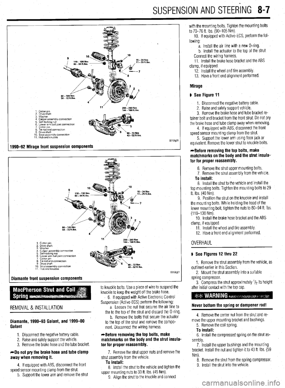
1 Cotter p,n
2 Drive shaft
3 Washer
4 Caliper assembly connecf~on
5 Self-IockIng ““f
6 Lower arm ball ,Ol”f Connectlo”
7 cotter PI”
8 T,e rod end connectton
9 Drive Shaft
10 Strut assembly connection
11 Hub and knuckle
1990-92 Mirage front suspension components
-
1 Cutter PI”
2 Drtve shaft
3 Washer
4 Ca,,perassembly connect~o”
5 Self-locking nut
6 Lower arm ball ,o,nt connection
7 cotter PI”
8 Tie rod end connection
9 Dwe shaft
10 Strut assembly connection
11 Hub and knuckie
Diamante front suspension components
1
to knuckle bolts Use a piece of wire to suspend the
knuckle to keep the weight off the brake hose.
6. If equipped with Active Electronrc Control
Suspension (Active-ECS) perform the followrng:
REMOVAL &INSTALLATION a. Loosen the nut that secures the an line to
the to the too of the strut and discard the O-ring.
Diamante, 1990-93 Galant, and 1999-00
Galant
1. Disconnect the negative battery cable.
2. Raise and safely support the vehicle.
3. Remove the brake hose and the tube bracket.
40 not pry the brake hose and tube clamp
awav when removino it.
b. Remove the bolts that secure the actuator
to the top of the strut and remove the compo-
nent. Disconnect the wiring harness.
*Before removing the top bolts, make
matchmarks on the body and the strut insula-
tor for proper reassembly.
7. Remove the strut upper nuts and remove the
strut assemblv from the vehicle.
4. If equipped with ABS, disconnect the front
speed sensor mounting clamp from the strut.
5. Support the lower arm and remove the strut
To instalf: 8. Install the strut to the vehicle and tighten the
upper mounting nuts to 33 ft. Ibs. (45 Nm)
9 Align the strut to the knuckle and connect with the mounting bolts. Tighten the mounting bolts
to 70-76 ft. Ibs. (90-105 Nm).
10. If equipped with Active-ECS, perform the fol-
lowing,
a. Install the air line with a new O-ring.
b Install the actuator to the top of the strut
Connect the wiring harness.
11. Install the brake hose bracket and the ABS
clamp, if equipped.
12. Install the wheel and tire assembly.
13. Have a front end alignment performed.
Mirage
# See Figure 11
1, Disconnect the negative battery cable.
2. Raise and safely support vehicle.
3. Remove the brake hose and tube bracket re-
tainer bolt and bracket from the front strut. Do not pry
the brake hose and tube clamp away when removrng.
4. If equipped with ABS, disconnect the front
speed sensor mounting clamp from the strut.
5. Support the lower arm usmg floor jack or
equivalent Remove the lower strut to knuckle bolts.
*Before removing the top bolts, make
matchmarks on the body and the strut insula-
tor for proper reassembly.
6. Remove the strut upper mounting bolts.
7. Remove the strut assembly from the vehicle.
To install: 8. Install the strut to the vehicle and install the
top mounting bolts, Tighten the mountrng bolts to 29
ft. Ibs. (40 Nm)
9. Position the strut on the knuckle and mstall
the mounting bolts, While holdrng the head of the
lower mounting bolt, tighten the nuts to 80-94 ft. Ibs.
(110-130 Nm).
10. Install the brake hose bracket and the ABS
clamp, if equipped
11 Install the wheel and tire assembly
12. Have a front end alignment performed.
OVERHAUL
) See Figures 12 thru 22
1. Remove the strut assembly from the vehicle, as
outlined earlier in this Section.
2. Mount the strut assembly into a suitable
spring compressor.
3. Compress the strut approximately r/a its height
after initial contact with the top cap.
Never bottom the spring or dampener rod!
4. Remove the center nut from the strut and re-
move the upper mounting bracket and bushings.
5. Remove the coil spring.
To install: 6. Install the compressed spring on the strut as-
sembly.
7. Install the upper bushings and the mounting
bracket Install the nut and tighten it to 43 ft. Ibs. (59
Nm).
8. Remove the strut from the spring compressor.
9. Install the strut into the vehrcle
Page 303 of 408
8-8 SUSPENSION AND STEERING
REMOVAL &INSTALLATION
199443 Galant
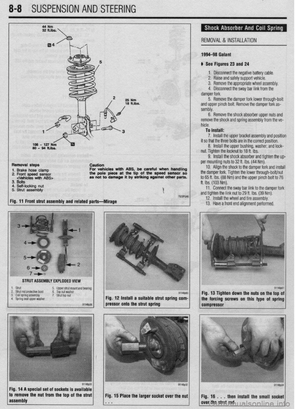
u See Figures 23 and 24
1 a Disconnect the neaative batterv cable.
I 3. Remove the appronnate wheel assembly.
25
Nm
18 fths.
I 2. Raise and safelv su~oort vehicle.
I I ,I 4. Disconnect the sway bar link from the
oamper rork.
5. Remove the damper fork lower through-bolt
and upper pinch bolt. Remove the damper fork as-
sembly.
6. Remove the shock absorber upper nuts and
remove the shock and spring assembly from the ve-
hicle.
To install:
7. Install the upper bracket assembly and position
it so that the three bolts are in the correct position.
8. Install the upper bushing, washer, and lock-
nut. Tighten the locknut to 18 ft.-lbs.
9. Install the shock absorber and tighten the up-
Removal steps
csution
1. Brake hose clamp For vehicles with ABS, be careful when handling
2. Front speed sensor the pole piece at the tip of the spaed sensor so
3. Bolts
4. Self-locking nut
5. Strut assembly
I
7wmA6
Fig. 11 Front strut assembly and related parts---Mirage ft. Ibs. (103 Nm).
11. Connect the sway bar link to the damoer fork per mounting nuts to 32 ft. Ibs. (44 Nm).
IO. Align the shock to the damper fork and install
the damper fork. Tighten the lower through-bolt/nut
to 65 ft. Ibs. (88 Nm) and the upper pinch bolt to 76
and tighten the link nut tb 29 ft. Ibs. (39 Nm):
12. Install the wheel and tire assembly.
13. Have a front end alignment performed.
I STRUT ASSEMBLY EXPLODED VIEW
I ,-
:-, : ;i
,\,.^ -_ I~.’ :“:;rL~~<
-_ cy -.:;;yp;:,
91146p?Jl Fig. 12 Install a suitable strut spring com-
91146p61 Fig. 13 Tighten down the nuts on the top of
the forcing screws on this type of spring
pressor onto the strut spring
compressor
Fig. 14 A special set of sockets Is available
to remove the nut from the top of the strut
Fig. 15 Place the larger socket over the nut
1 ;ir ;;ostrut;;; install the small soi8oet
Page 304 of 408
SUSPENSION AND STEER'ING 8-9
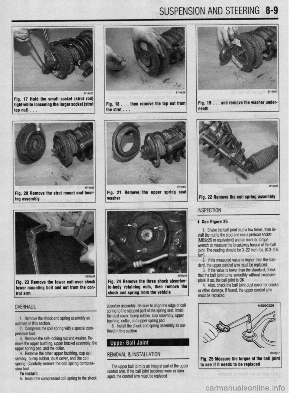
ile loosening the larger socket (strut then remove the top nut from
91148ps4 1 Fig. 29 Remove the strut mount and bear-
ins assembly 1 Fig. 21 Remove the upper spring seat 1
washer
91148PS7
Fig. 19 . t , and remove the washer under-
neath
Fig. 22 Remove the coil spring assembly
INSPECTION
’ ) See Figure 25
Fig. 23
Remove the lower coil-over shock
lowar mounting bolt
and nut from the con- 1.
Shake the ball joint stud a few times, then in-
stall the nut to the stud and use a preload socket
(MB9c26 or equivalent) and an inch lb. torque
wrench to measure the breakaway torque of the ball
joint. The reading should be 3-22 inch Ibs. (0.3-2.5
Nm).
2.
If the measured value is higher than the stan-
dard, the upper control arm must be replaced.
3.
If the value is lower than the standard, check
that the ball joint turns smoothly without excessive
Fig. 24 Remove the three shock absorber- plate. If so, the ball joint is OK. to-body retaining nuts, the 4.
Also, check the ball joint dust cover for cracks
or other damage, if found, the upper control arm
must be replaced.
1.
outlin
OVERHAUL
Remove the shock and spring assembly as
ed in this section.
Compress the coil spring with a special com-
ion tool.
Remove the self-locking nut and washer. Re-
the upper bushing, upper bracket assembly, the
sorina oad. and the collar. absorber assembly. Be sure to align the edge of coil
sorina to the steoaed Dart of the spring Seat. laSk3ll assembly, upper
nad
2.
press
3.
move
upper
4. dem&e the other upper bushing, cup as-
sembly, bump rubber, dust I cover, and the coil
spring. Carefully remove the coil spring compres-
sion tool.
To install:
5. Install the compressed coil spring to the shock
REMOVAL &INSTALLATION
Thp lwwr hall inint is an inkoral oart of the umer
6e d&cover, d;mp iubber, cup
bushing, collar, and upper spring r--.
6. Install the shock and spring assembly as out-
lined in this section.
Fig. 25 Measure the toruue of the ball joint
to see if it needs to be t&laced
..*., “rf.l’ “m.. ,-.,.. .--.. . ...-=.- r-. . .rr
control arm. If the ball joint becomes worn or dam-
aged, the control arm must be replaced.
Page 308 of 408
SUSPENSION AND STEERING 8-13
W-118 Nm*
71-W ft.lbs: 83Nm
69-78 Nm
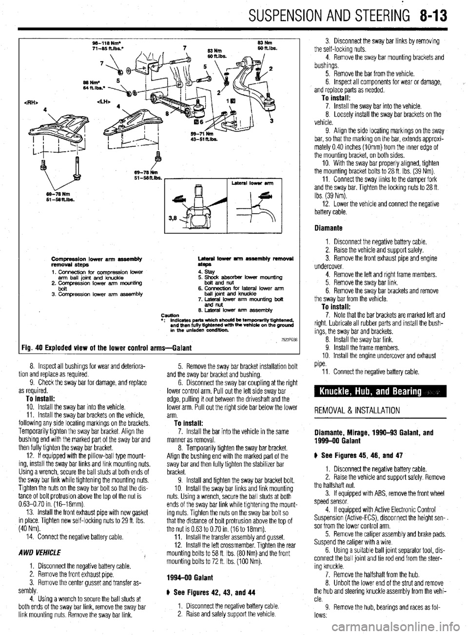
Compression lower arm assembly
removal steps
1. Connection for compression lower
arm ball joint and knuckle
2. Comoression lower arm mouniina Lateral lower tmn assembly removal
steps
4. stay
bon ’ 3. Compression lower arm assembly 6. CMlnection for lateral lower arm
ball joint and knuckle
7. lateral lower arm mounting boll
andnllt
0. hleral lower am7 assembly
CWtlOtl
l : Indicates parts which should be temporarily tightened,
and then fully tightened with the vehicle on the ground
in the unladen condition
7923PGB8 Fig. 40 Exploded view of the lower control arms-Galant
tion and replace as required. 8.
9. Inspect all bushings for wear and deteriora-
Check the sway bar for damage, and replace
as required.
To install: 10. Install the sway bar into the vehicle.
11. Install the sway bar brackets on the vehicle,
following any side locating markings on the brackets.
Temporarily tighten the sway bar bracket. Align the
bushing end with the marked part of the sway bar and
then fully tighten the sway bar bracket.
12. If equipped with the pillow-ball type mount-
ing, install the sway bar links and link mounting nuts.
Using a wrench, secure the ball studs at both ends of
the sway bar link while tightening the mounting nuts.
Tighten the nuts on the sway bar bolt so that the dis-
tance of bolt protrusion above the top of the nut is
0.63-0.70 in. (1&18mm).
13. Install the front exhaust pipe with new gasket
in place. Tighten new self-locking nuts to 29 ft. Ibs.
(40 Nm). and the sway bar bracket and bushing.
6. 5. Remove the sway bar bracket installation bolt
Disconnect the sway bar coupling at the right
lower control arm. Pull out the left side sway bar
edge, pulling it out between the driveshaft and the
lower arm. Pull out the right side bar below the lower
arm.
To install:
14. Connect the negative battery cable.
A WD VEHICLE
I
1. Disconnect the negative battery cable.
2. Remove the front exhaust pipe.
3. Remove the center gusset and transfer as-
sembly.
4. Using a wrench to secure the ball studs at
both ends of the sway bar link, remove the sway bar
link mounting nuts. Remove the sway bar link. 11. Connect the negative battery cable.
REMOVAL & INSTALLATION
7. Install the bar into the vehicle in the same Diamante, Mirage, 1996-93 Galant, and manner as removal. 1999-00 Galant 8. Temporarily tighten the sway bar bracket.
Align the bushing end with the marked part of the
sway bar and then fully tighten the stabilizer bar
bracket.
9. Install and tighten the sway bar bracket bolt.
10. Install the sway bar links and link mounting
nuts Using a wrench, secure the ball studs at both
ends of the sway bar link while tightening the mount-
ing nuts. Tighten the nuts on the sway bar bolt so
that the distance of bolt protrusion above the top of
the nut is 0.63 to 0.70 in. (16 to 18mm).
11. Install the transfer assembly and gusset.
12. Install the left crossmember. Tighten the rear
mounting bolts to 58 ft Ibs. (80 Nm) and the front
mounting bolts to 72 ft. Ibs. (100 Nm). ) See Figures 45, 46, and 47
1. Disconnect the negative battery cable.
2. Raise the vehicle and support safely. Remove
the halfshaft nut.
3. If equipped with ABS, remove the front wheel
speed sensor
1994-90 Galant
4. If equipped with Active Electronic Control
Suspension (Active-ECS), disconnect the height sen-.
sor from the lower control arm.
5. Remove the caliper assembly and brake pads.
Suspend the caliper with a wire
6. Using a suitable ball joint separator tool, dis-
connect the ball joint and tie rod end from the steer-
ing knuckle.
7. Remove the halfshaft from the hub.
8. Unbolt the lower end of the strut and remove
the hub and steering knuckle assembly from the vehi-
cle.
9 Remove the hub, bearings and races as fol-
lows.
# See Figures 42, 43, and 44
1. Disconnect the negative battery cable.
2. Raise and safely support the vehicle 3. Disconnect the sway bar links by removing
the self-locking nuts.
4. Remove the sway bar mounting brackets and
bushings.
5. Remove the bar from the vehicle.
6. Inspect all components for wear or damage,
and replace parts as needed.
To install: 7. Install the sway bar into the vehicle.
8. Loosely install the sway bar brackets on the
vehicle.
9. Align the side locating markings on the sway
bar, so that the marking on ihe bar, extends approxi-
mately 0.40 inches (1Omm) from the Inner edge of
the mounting bracket, on both sides.
10. With the sway bar properly aligned, tighten
the mounting bracket bolts to 28 ft. Ibs. (39 Nm).
11. Connect the sway links to the damper fork
and the sway bar. Tighten the locking nuts to 28 ft.
Ibs (39 Nm).
12. Lower the vehicle and connect the negative
battery cable.
Diamante
1. Disconnect the negative battery cable.
2. Raise the vehicle and support safely.
3. Remove the front exhaust pipe and engine
undercover.
4. Remove the left and right frame members.
5. Remove the sway bar link.
6. Remove the sway bar brackets and remove
the sway bar from the vehicle.
To install: 7. Note that the bar brackets are marked left and
right. Lubricate all rubber parts and install the bush-
ings, the sway bar and brackets.
8. Install the sway bar link.
9. Install the frame members.
10. Install the engine undercover and exhaust
pipe.
Page 310 of 408
SUSPENSION AND STEERING 845
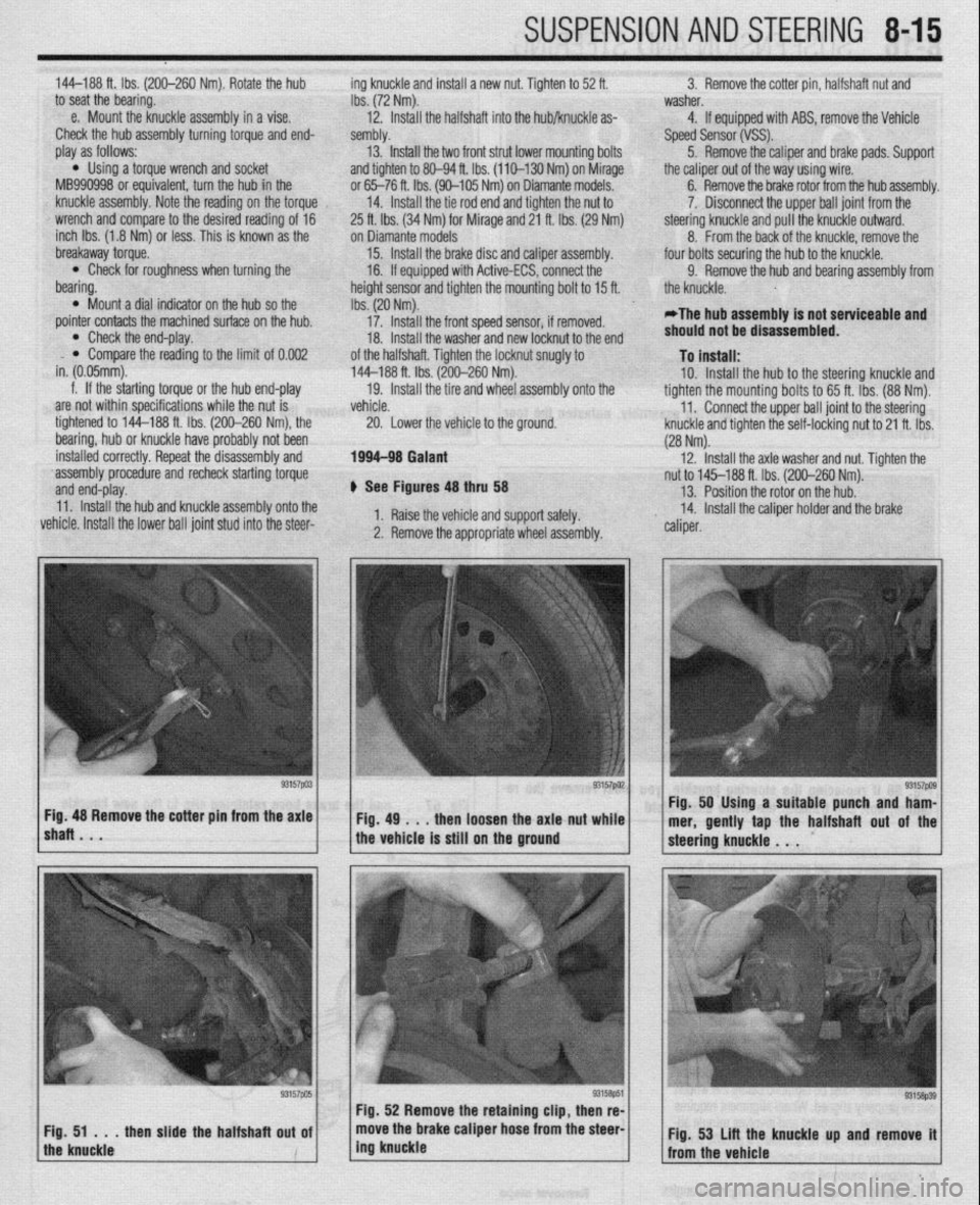
144-188 ft. Ibs. (200-260 Nm). Rotate the hub ing knuckle and install a new nut. Tighten to 52 ft. 3. Remove the cotter pin, halfshaft nut and
to seat the bearing.
Ibs. (72 Nm). washer.
e. Mount the knuckle assembly in a vise.
12. Install the halfshaft into the hub/knuckle as- 4. If equipped with ABS, remove the Vehicle
Check the hub assembly turning torque and end- sembly.
Speed Sensor (VSS).
play as follows: 13. Install the two front strut lower mounting bolts
5. Remove the caliper and brake pads. Support
l Using a torque wrench and socket
and tighten to 80-94 ft. Ibs. (110-130 Nm) on Mirage
the caliper out of the way using wire.
MB990998 or equivalent, turn the hub in the or 65-76 ft. Ibs. (90-105 Nm) on Diamante models. 6. Remove the brake rotor from the hub assembly.
knuckle assembly. Note the reading on the torque
14. Install the tie rod end and tighten the nut to 7. Disconnect the upper ball joint from the
wrench and compare to the desired reading of 16
25 ft. lbs. (34 Nm) for Mirage and 21 ft. Ibs. (29 Nm) steering knuckle and pull the knuckle outward.
inch Ibs. (1.8 Nm) or less. This is known as the ‘on Diamante models
8. From the back of the knuckle, remove the
breakaway torque.
15. Install the brake disc and caliper assembly. ‘four bolts securing the hub to the knuckle.
l Check for roughness when turning the
16. If equipped with Active-ECS, connect the
9. Remove the hub and bearing assembly from
bearing.
height sensor and tighten the mounting bolt to 15 ft.
the knuckle.
0 Mount a dial indicator on the hub so the
Ibs. (20 Nm).
pointer contacts the machined surface on the hub.
17. Install the front speed sensor, if removed.
*The hub assembly is not serviceable and
l Check the end-play.
18. Install the washer and new locknut to the end should not be disassembled.
l Compare the reading to the limit of 0.002
in. (0.05mm). of the halfshaft. Tighten the locknut snugly to To install: 144-188 ft. Ibs. (200-260 Nm).
f. If the starting torque or the hub end-play
19. Install the tire and wheel assembly onto the 10. Install the hub to the steering knuckle and
are not within specifications while the nut is tighten the mounting bolts to 65 ft. Ibs. (88 Nm).
vehicle.
11.
tightened to 144-188 ft. Ibs. (200-260 Nm), the
Lower the vehicle to the ground. Connect the upper ball joint to the steering
20.
bearing, hub or knuckle have probably not been ‘knuckle and tighten the self-locking nut to 21 ft. Ibs.
(28 Nm).
installed correctly. Repeat the disassembly and 1994-98 Galant 12.
‘assembly procedure and recheck starting torque Install the axle washer and nut. Tighten the
and end-play. nut to 145-188 ft. Ibs. (200-260 Nm).
+ See Figures 48 thru 58 13. Position the rotor on the hub.
11. Install the hub and knuckle assembly onto the
vehicle. Install the lower ball joint stud into the steer- 1. Raise the vehicle and support safely. 14. Install the caliper holder and the brake
2. Remove the appropriate wheel assembly. ” caliper.
lshaRBmV * “57pa3~ ~Fig.4g~..thenloosehtheaxlattut~~;.~ Fig. 48 Remove the cotter pm from the axle Fig. 50 Using a suitable punch and ham-
mer, gently tap the halfshaft out of the
the vehicle is still on the ground
Page 311 of 408
8116 SUSPENSION AND STEERING
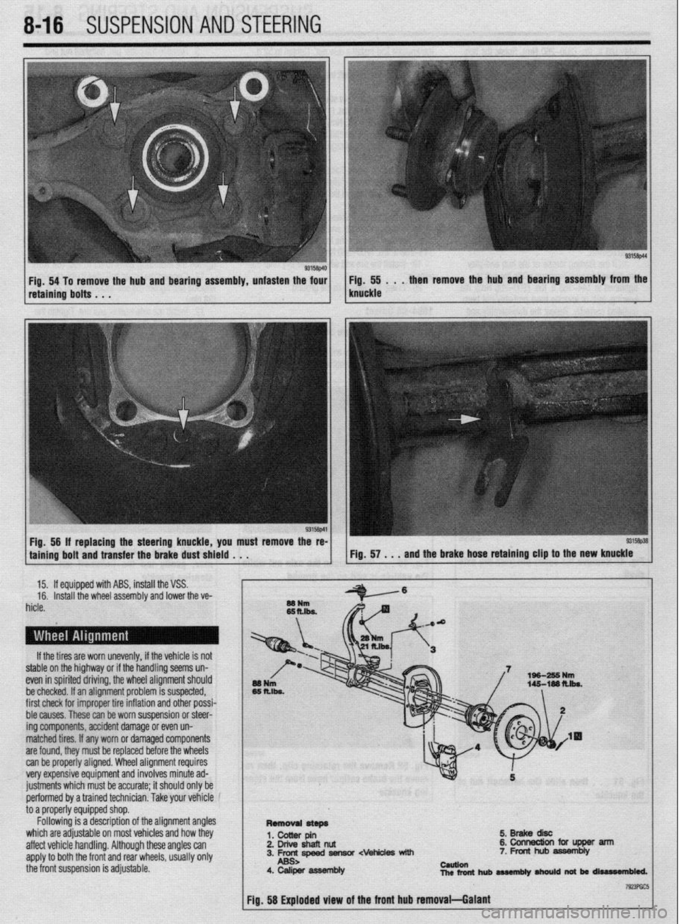
Fig. 54 To remove the hub and bearing assembly, unfasten the four Fig. 55 . . . then remove the hub and bearing assembly from the
retaining bolts . . . knuckle
Fig, 56 If replacing the steering knuckle, you must remove the re-
taining bolt and transfer the brake dust shield . . .
15. If equipped with ABS, install the VSS.
16. Install the wheel assembly and lower the ve-
hicle.
If the tires are worn unevenly, if the vehicle is not
stable on the highway or if the handling seems un-
even in spirited driving, the wheel alignment should
be checked. If an alignment problem is suspected,
first check for improper tire inflation and other possi-
ble causes. These can be worn suspension or steer-
ing components, accident damage or even un-
matched tires. If any worn or damaged components
are found, they must be replaced before the wheels
can be properly aligned. Wheel alignment requires
very expensive equipment and involves minute ad-
justments which must be accurate; it should only be
performed by a trained technician. Take your vehicle
to a properly equipped shop.
Following is a description of the alignment angles
which are adjustable on most vehicles and how they
affect vehicle handling. Although these angles can
apply to both the front and rear wheels, usually only
the front suspension is adjustable.
5.BrakediW
2. Drive shafl nut &collnectionfciflJpperarm
3. Frc-rc,speed fiensor cvehides with 7. Front hub assembly
4. Caliper asWmbly cauuen
nlcrfonthubaMmbly~natbrrliurr#n61ed.
Page 316 of 408
.
SUSPENSION AND STEERING 8-21
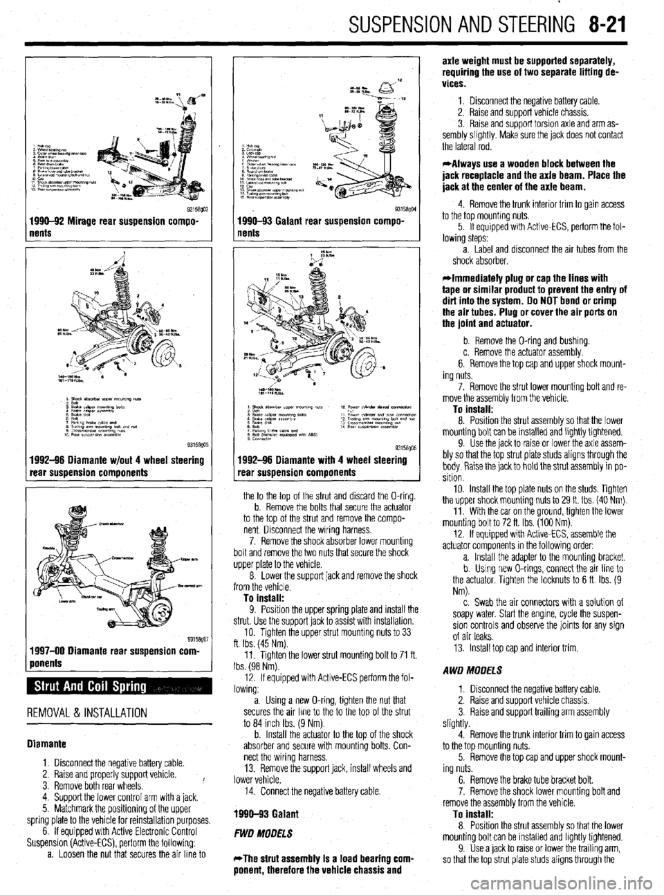
1 nents Q3158!@3 1990-92 Mirage rear suspension compo-
1992-96 Diamante w/out 4 wheel steering
rear suspension components
1 ponents %” 1997-00 Diamante rear suspension corn
REMOVAL & INSTALLATION
Diamante
1. Disconnect the negative battery cable.
2. Raise and properly support vehicle.
3. Remove both rear wheels. !
4. Support the lower control arm with a jack.
5. Matchmark the positioning of the upper
spring plate to the vehicle for reinstallation purposes.
6. If equipped with Active Electronic Control
Suspension (Active-ECS), perform the following:
a. Loosen the nut that secures the air line to
I
93158QM 1990-93 Galant rear suspension compo-
nents
1992-96 Diamante with 4 wheel steering
rear suspension components
the to the top of the strut and discard the O-ring.
b. Remove the bolts that secure the actuator
to the top of the strut and remove the compo-
nent Disconnect the wiring harness.
7. Remove the shock absorber lower mounting
bolt and remove the two nuts that secure the shock
upper plate to the vehicle.
8. Lower the support jack and remove the shock
from the vehicle.
To install:
9. Position the uooer sprina elate and install the
strut. Use the support’jack to as% with installation.
10. Tighten the upper strut mounting nuts to 33
ft. Ibs. (45 Nm).
11. Tighten the lower strut mounting bolt to 71 ft.
Ibs. (98 Nm).
12. If equipped with Active-ECS perform the fol-
lowing:
a. Using a new O-ring, tighten the nut that
secures the air line to the to the top of the strut
to 84 inch Ibs. (9 Nm).
b. Install the actuator to the top of the shock
absorber and secure with mounting bolts. Con-
nect the wiring harness.
13. Remove the support jack, install wheels and
lower vehicle.
14. Connect the negative battery cable.
1990-93 Galant
FWD MODELS
*The strut assembly Is a load bearing com-
ponent, therefore the vehicle chassis and axle weight must be supported separately,
requiring the use of two separate lifting de-
vices.
1. Disconnect the negative battery cable.
2. Raise and support vehicle chassis.
3. Raise and support torsion axle and arm as-
sembly slightly. Make sure the jack does not contact
the lateral rod.
*Always use a wooden block between the
jack receptacle and the axle beam. Place the
jack at the center of the axle beam.
4. Remove the trunk interior trim to gain access
to the top mounting nuts.
5. If equipped with Active-ECS, perform the fol-
lowing steps:
a. Label and disconnect the air tubes from the
shock absorber.
*Immediately plug or cap the lines with
tape or similar product to prevent the entry of
dirt into the system. Do NOT bend or crimp
the air tubes. Plug or cover the air ports on
the joint and actuator.
b. Remove the O-ring and bushing.
c. Remove the actuator assembly.
6. Remove the top cap and upper shock mount-
ing nuts.
7. Remove the strut lower mounting bolt and re-
move the assembly from the vehicle.
To install:
8. Position the strut assembly so that the lower
mounting bolt can be installed and lightly tightened.
9. Use the jack to raise or lower the axle assem-
bly so that the top strut plate studs aligns through the
body. Raise the jack to hold the strut assembly in po-
sition
10. Install the top plate nuts on the studs. Tighten
the upper shock mounting nuts to 29 It. Ibs. (40 Nm).
11. With the car on the ground, tighten the lower
mounting bolt to 72 ft. Ibs. (100 Nm).
12. If equipped with Active-ECS, assemble the
actuator components in the following order:
a. Install the adapter to the mounting bracket.
b. Using new O-rings, connect the air line to
the actuator, Tighten the locknuts to 6 ft Ibs. (9
Nm).
c. Swab the air connectors with a solution of
soapy water. Start the engine, cycle the suspen-
sion controls and observe the joints for any sign
of air leaks.
13. Install top cap and interior trim.
AWD MODELS
1. Disconnect the negative battery cable.
2. Raise and support vehicle chassis.
3. Raise and support trailing arm assembly
slightly.
4. Remove the trunk interior trim to gain access
to the top mounting nuts.
5. Remove the top cap and upper shock mount-
ing nuts.
6. Remove the brake tube bracket bolt.
7. Remove the shock lower mounting bolt and
remove the assembly from the vehicle.
To install:
8. Position the strut assembly so that the lower
mounting bolt can be installed and lightly tightened.
9. Use a jack to raise or lower the trailing arm,
so that the top strut plate studs aligns through the
Page 317 of 408
sembly slightly.
3. In order to gain access to the top mounting
nuts, remove the rear seat as follows:
r
I-- a. While pulling the rear seat stopper out- lb
ward, lift the lower cushion upward. Remove the
lower cushion.
b. Remove the seat back mounting bolts.
c. Lift the seat back upward and remove the
seat.
4. Remove the shock upper mounting nuts.
5. Remove the shock lower mounting bolt and
remove the assembly from the vehicle.
To install:
6. Position the shock assembly so that the
lower mounting bolt can be installed and lightly
tightened.
7. Use a jack to raise or lower the lower control
arm, so that the top shock plate studs align through
the body. Raise the jack to hold the shock assembly
in position.
8 “, In&dl the tnn nlato nl Itc: nn thp dl~rk nnri ,,,“Lu,l .,,” .“* r....” ,.“.., “.. . ..” -.I__-..” tighten the mounting nuts to 32 ft. Ibs. (44 Nm).
9. With the vehicle on the ground, tighten the
lower mounting bolt to 71 ft. Ibs. (98 Nm).
10. Install the rear seat back and cushion.
Miraae
I
1. Remove the trunk interior trim to aain access
to the top mounting nuts.
2. Remove the top cap and upper shock mount-
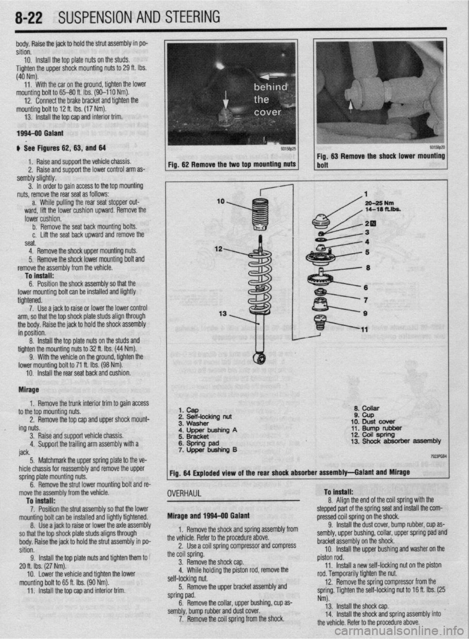
I 1. cap
2 Beif-locking nut
Q* ,A,ll)rrr ii ZPb
10: Dust cbver
11. Bump rubber 12. Coil spring
8-22 SUSPENSION AND STEERING
,
I
ing nuts.
3. Raise andsupport vehicle chassis.
4. Support the trailing arm assembly with a
iack a. ““QJ1vw
;. ~~;~~inp A
6: Spring pad 7. Upper bushing B 13. Shock absorber assembly
I----. 5 Matchmark thF! unner snrino elate to the ve-
I TmFliBl
_. .._._....._... . .._ -TT- _r
u r _.- .-
hicle chassis for reassembly and remove the upper
spring plate mounting nuts.
^ ^
. . .a .I II. I Fig. 64 Exploded view of the rear shock absorber assembly-Galant and Mirage
I
-t
Inrmg DOII ana re-
9.
OVERHAUL To Install:
o A*. .* I b. nemove tne strut lower mol
move the assembly from the vehicle
To install:
7. Position the strut assembly so that the lower
mountino bolt can be installed and liahtlv tiahtened.
8. t&e a jack to raise or lower thk &le&sembly
so that the top shock plate studs aligns through
body. Raise the jack to hold the strut assembly in po-
sition.
9. Install the top plate nuts and tighten them to
20 ft. Ibs. (27 Nm).
mounting bolt to 65 ft. Ibs. (90 Nm).
11. Install the top cap and interior trim. Mirage and 1996-00 Galant 0. ,,ngn me ena of the coil spring with the
stepped part of the spring seat and install the com-
pressed cnil snrinn nn the shock
1. Remove the shock and spring assembly from
the vehicle. Refer to the procedure above.
2. Use a coil spring compressor and compress
the coil spring.
3. Remove the shock cap.
” \w.;,n hrrh~inn +I-.- n;r+nn rnr( rnmn,rc, thn ,. .,,,,,- ,,-,-,* *J ..l” r .I._. * .-_, .-...-.- . ..-
self-locking nut.
5. Remove the upper bracket assembly and
spring pad.
6. Remove the collar, upper bushing, cup as-
sembly, bump rubber and dust cover.
7. Remove the coil spring from the shock. _.. -r,.. J _ _ _ __
9. Install the dust cover, bump rubber, cup as-
sembly, upper bushing, collar, upper spring pad and
bracket assembly on the shock.
10. Install the upper bushing and washer on the
piston rod.
11. Install a new self-locking nut on the piston
roa. temporarily tighten the nut.
12. Remove the spring compressor from the
spring. Tighten the self-locking nut to 16 ft. Ibs. (25
Nm).
13. Install the shock cap.
14. Install the shock and spring assembly into
the v&i&a Rnfnr tn the nmrd~w~ ahnrm
Page 318 of 408
SUSPENSION AND STEERING 8-23
i-l
12. Check rear wheel alignment and adjust if nec-
REMOVALANDINSTALLATION
essary.
1990-93 Galant
1. Disconnect the neoative battetv cable.
2. Raise and safely sipport vehicle.
3. Remove the tire and wheel assembly.
4. Support the rear lower control arm.
5. Remove the brake line clamp bolt.
6. Remove the nut and separate the upper ball
joint, using tool MB9f35 or equivalent, from the rear
trailing arm/steering knuckle.
*It is important to use proper method of
joint separation when reusing joint. Damage
can result from unapproved methods, result-
ing in possible joint failure.
7. Matchmark the eccentric nn the IInner instal-
8. Remove the upper arm from the vehicle.
To install:
9. Install the arm to the vehicle and install the
upper arm installation bolt. Align the matchmarks
and tighten the nut snugly only.
10. Install the upper arm ball joint to the rear
spindle assembly and install new nut. Tighten to 52
ft. Ibs. (72 Mm).
11. Install the tire and wheel assembly.
12. Lower the vehicle until the suspension sup-
ports its weight.
13. Tighten the upper arm installation bolt to 116
ft. Ibs. (160 Nmj. 1. Disconnect the negative battery cable.
- . .._...- -.. . ..- -rr-. lation bolt and remove from the control arm.
14. ‘Check the rear wheel alignment.
1994-98 Galant
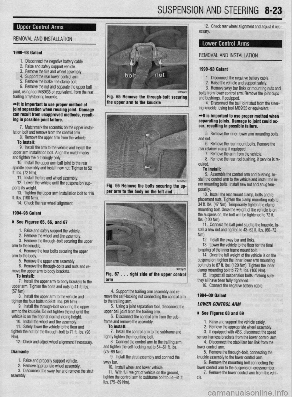
ti See Figures 65, 66, and 67 1
REMOVAL AND INSTALLATION
1990-93 Galant
2. Raise the vehicle and support safely.
!4315ap22 3. Remove sway bar links or mounting nuts and
Fig. 65 Remove the through-bolt securing bolts from lower control arm. Remove the joint cups
the upper arm to the knuckle and bushings, if equipped.
4. Disconnect the ball joint stud from the steer-
ing knuckle, using tool MB9f35 or equivalent.
*It is important to use proper method when
separating joints. Damage to joint could oc-
cur, resulting in possible failure.
5. Remove the inner lower arm mounting bolts
and nut.
6. Remove the rear mount bolts. Remove the
rear retainer clamp if equipped.
7. Remove the arm from the vehicle.
8. Remove the rear rod bushing, if service is re-
quired.
To install:
9. Assemble the control arm and bushing. In-
stall the control arm to the vehicle and install the in-
ner mounting bolts. Install new nut and snug tem-
nnrarilv md . . . 1 f.r”‘Y”‘,.
10. Install the rear mount clamp, bolts and re-
placement nuts. Tighten the clamp mounting nuts to
34 ft. Ibs. (47 Nm). Temporarily tighten the clamp
mounting bolt. Once the weight of the vehicle is on
the suspension, the bolt will be tightened to 72 ft.
Ibs. (100 Nm).
4. Support the trailing arm assembly and re-
move the Self-locking nut connecting the control arm
.* 11. Connect the ball joint stud to the knuckle. In-
stall a new nut and tighten to 43-52 ft. Ibs. (60-72
Nm).
12. Install the swav bar and links.
to tne tramng arm.
5. Using a joint separation tool, disconnect the
upper ball joint from the trailing ary.
6. Disconnect the control arm from the sub-
frame and remove the assembly.
To install:
7. Install the control arm to the subframe and
liahtlv tiahten the mounting bolt.
rol arm to the trailina arm 13. Lower the vehicle to the floor for the final
torquing of the inner frame mount bolt.
14. Once the full weight of the vehicle is on the
suspension, tighten the inner lower arm mounting
bolt nuts to 87 ft. Ibs. (120 Nm). Tighten the inner
clamp mounting bolt to 72 ft. Ibs. (100 Nm).
15. InSpet all suspension bolts, making sure
they all have been fully tightened.
16. Connect the negative battery cable.
199440 Gafant
LOWER CONTROL ARM
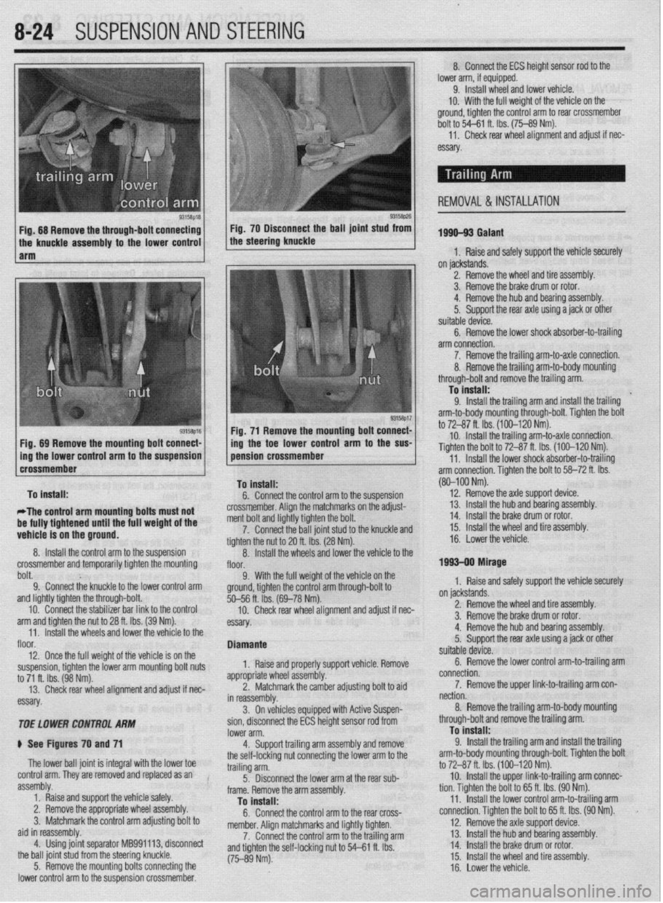
+ See Figures 68 and 69
1. Raise and support the vehicle safely.
2. Remove the appropriate wheel assembly.
3. If equipped with ABS, disconnect the speed
sensor harness brackets from the lower control arm.
4. Disconnect the stabilizer bar link from the
----“‘-‘I’
1 b Raise and safely support the vehicle.
2. Remove the wheel and tire assembly.
3. Remove the through-bolt securing the upper
arm to the knuckle.
4. Remove the four bolts securing the upper
arm to the body.
5. Remove the uooer arm assemhlv
re-
move the upper arm to body brackets,
To install:
7. Install the upper arm to body brackets to the
upper arm. Tighten the bolts and nuts to 41 ft. Ibs.
(57 Nm).
8. Install the upper arm to the vehicle and
tighten the four bolts to 28 ft. Ibs. (39 Nm). 6. Remove the through-bolts and nuts and
9. Install the through-bolt securing
vehicle is on the floor at normal ridina heiaht.
10. Install the wheel and tire assekbly:
11. Safely lower the vehicle to the floor and
tighten the nut for the through-bolt to 71 ft. Ibs. (98
Nm).
i2. Check and adjust wheel alignment if necessary. 8’. eonnectthe&i
and tighten the self-locki
(75-89 Nm). ng nut to 54-61 ft. Ibs.
connect the lower control arm.
5. Remove the through-bolt, connecting the
knuckle assembly to the lower control arm.
fi Romn\fn +hn mwntinn hnlt cnnnwtinn the 9. Install the strut assembly and
sway bar.
10. Install wheel and lower vehicle. V. IIVIII”“~ OK, ill” -...... J I”.. --....--.... J .,,” lower control arm to the suspension crossmember. Diamante
1, Raise and properly support vehicle.
2. Remove appropriate wheel assembly.
3. Disconnect the sway bar and remove the strut
assembly. 11. With full weight of vehicle on the ground,
tighten the control arm to subframe bolt to 54-61 ft.
Ibs. (75-89 Nm). 7. Remove the lower control arm from the vehi-
cle.
Page 319 of 408
8-24 SUSPENSION AND STEERING
9315t$M 93158p26 Fig. 68 Remove the through-bolt connecting Fig. 70 Disconnect the ball joint stud from
the knuckle assembly to the lower control the steering knuckle
1 arm
Fig. 71 Remove the mounting bolt connect-
Fig, 89 Remove the mounting bolt connect- /
1 ing the toe lower control arm to the SW
Dolt. 9; Connect the knuckle to the lower control arm 9. With the full weigh
ground, tighten the control
and lightly tighten the through-bolt.
10. Connect the stabilizer bar link to the control
arm and tighten the nut to 28 ft. Ibs. (39 Nm).
11. Install the wheels and lower the vehicle to the
floor.
12. Once the full weight of the vehicle is on the
suspension, tighten the lower arm mounting bolt nuts
to 71 ft. Ibs. (98 Nm).
13. Check rear wheel alignment and adjust if nec-
essary.
TOE LOWER CONTROL ARhl
ti See Figures 70 and 71
The lower ball joint is integral with the lower toe
control arm. They are removed and replaced as an
assembly.
1. Raise and support the vehicle safely.
2. Remove the appropriate wheel assembly.
3. Matchmark the control arm adjusting bolt to
aid in reassembly.
4. Using joint separator MB991113, disconnect
the ball joint stud from the steering knuckle.
5. Remove the mounting bolts connecting the
lower control arm to the suspension crossmember. %--56 ft. ibs. (
10. Check
essay. rem an0 aajusr
II nec-
orl vehicle Remove
ldiustina bolt to aid
soen- Diamante
1, Raise and properly supp
appropriate whl
eel assembly.
2. Matchn
narkthe camber a , _
in reassembly.
3. On vehicles equipped with Active Su r
sion, disconnect the ECS height sensor rod from
lower arm.
4. Support trailing arm assembly and remove
the self-locking nut connecting the lower arm to the
trailing arm.
5. Disconnect the lower arm at the rear sub-
frame. Remove the arm assembly.
To install:
6. Connect the control arm to the rear cross-
member. Alion matchmarks and liahtlv tiohten.
7. Connect the control arm tothe trailing arm
and tighten the self-locking nut to 54-P e rho I I IL IY.J.
(75-89 Nm). 8. Connect the ECS height sensor rod to the
lower arm, if equipped.
9. Install wheel and lower vehicle.
IO. With the full weight of the vehicle on the
ground, tighten the control arm to rear crossmember
bolt to 54-61 ft. Ibs. (75-89 Nm).
11,
Check rear wheel alignment and adjust if nec-
essary
1996-93 Galant
1, Raise and safely support the vehicle securely
on jackstands.
2. Remove the wheel and tire assembly.
3. Remove the brake drum or rotor.
4. Remove the hub and bearing assembly.
5.
Support the rear axle using a jack or other
suitable device.
6. Remove the lower shock absorber-to-trailing
arm connection.
7. Remove the trailing arm-to-axle connection.
REMOVAL & INSTALLATION
(80-100 Nm).
12.
Remove the axle suooort device.
on jackstands.
2. Remove the wheel and tire assembly.
3. Remove the brake drum or rotor.
4. Remove the hub and bearing assembly.
5.
Support the rear axle using a jack or other
suitable device.
6. Remove the lower control arm-to-trailing arm
connection.
7. Remove the upper link-to-trailing arm con-
nection.
8. Remove the trailing arm-to-body mounting
through-bolt and remove the trailing arm.
To install:
9.
Install the trailing arm and install the trailing
arm-to-body mounting through-bolt. Tighten the bolt
to 72-87 ft. Ibs. (100-120 Nm).
10. Install the upper link-to-trailing arm connec-
tion. Tighten the bolt to 65 ft. Ibs. (90 Nm).
11. Install the lower control arm-to-trailing arm
connection. Tighten the bolt to 65 ft. Ibs. (90 Nm).
12. Remove the axle support device.
13. Install 1 he hub and bearing assembly.
14 Install 1
. _ .he brake drum or rotor.
15.
Install the wheel and tire assembly.
16. Lower the vehicle.