weight MITSUBISHI DIAMANTE 1900 Repair Manual
[x] Cancel search | Manufacturer: MITSUBISHI, Model Year: 1900, Model line: DIAMANTE, Model: MITSUBISHI DIAMANTE 1900Pages: 408, PDF Size: 71.03 MB
Page 8 of 408
GENERALINFORMATIONAND MAINTENANCE l-9
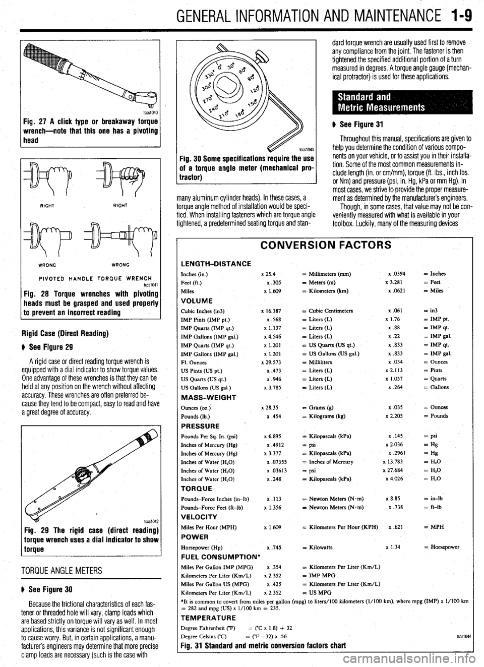
Fig. 27 A click type or breakaway torque
wrench-note that this one has a pivoting
head
v
WRONG WRONG
PIVOTED HANDLE TOR(IUE WRENCH tccS1041 Fig. 28 Torque wrenches with pivoting
heads must be grasped and used properly
to prevent an incorrect reading
Rigid Case (Direct Reading)
# See Figure 29
A rigid case or direct reading torque wrench is
equipped with a dial indicator to show torque values.
One advantage of these wrenches is that they can be
held at any position on the wrench without affecting
accuracy. These wrenches are often preferred be-
cause they tend to be compact, easy to read and have
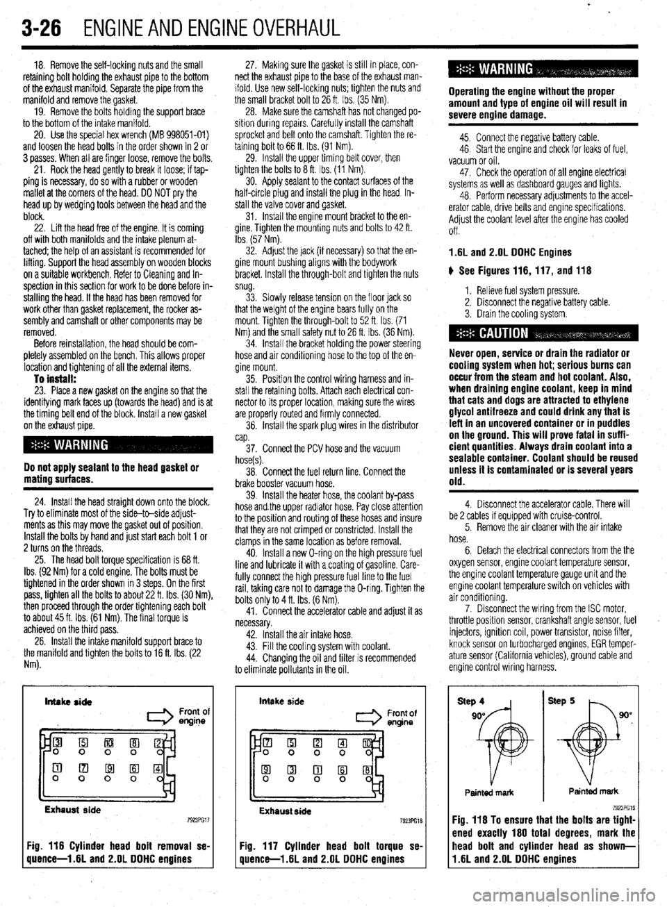
a great degree of accuracy.
lccs1042 Fig. 29 The rigid case (direct reading)
torque wrench uses a dial indicator to show
torque
TORQUEANGLEMETERS
# See Figure 30
Because the frictional characteristics of each fas-
tener or threaded hole will vary, clamp loads which
are based strictly on torque will vary as well. In most
applications, this variance IS not significant enough
to cause worry. But, in certain applications, a manu-
facturers engineers may determine that more precise
clamp loads are necessary (such is the case with :ig. 30 Some specifications require the use
rf a torque angle meter (mechanical pro.
ractor)
many aluminum cylinder heads). In these cases, a
torque angle method of installation would be speci-
fied. When installing fasteners which are torque angle
tightened, a predetermined seating torque and stan- dard torque wrench are usually used first to remove
any compliance from the joint. The fastener is then
tightened the specified additional portion of a turn
measured in degrees. A torque angle gauge (mechan-
ical protractor) is used for these applications.
) See Figure 31
Throughout this manual, specifications are given to
help you determine the condition of various compo-
nents on your vehicle, or to assist you in their installa-
tion. Some of the most common measurements in-
clude length (in. or cm/mm), torque (ft. Ibs., inch Ibs.
or Nm) and pressure (psi, in. Hg, kPa or mm Hg). In
most cases, we strive to provide the proper measure-
ment as determined by the manufacturers engineers.
Though, in some cases, that value may not be con-
veniently measured with what is available in your
toolbox. Luckily, many of the measuring devices
CONVERSION FACTORS
LENGTH-DISTANCE Inches (I”.) x 25.4 = Millimeters (mm) x .0394 = Inches
Feet (ft.) x ,305
= Meters (m) x 3.281 = Feet
Miles x 1.609 = Kilometers (km) x .0621
= Miles
VOLUME Cubic Inches (in3) x 16.387 = Cubic Centimeters x .061 = in3
IMP Pints (IMP pt.) x .568 = Liters (L) x 1.76
= IMP pt.
IMP Quarts (IMP qt.) x 1.137 = Liters (L) x .88 = IMP qt.
IMP Gallons (IMP gal.) x 4.546 = Liters (L) 7, .22
= IMP gal.
IMP Quarts (IMP qt ) x 1.201 = US Quarts (US qt.) x ,833 = IMP qt.
IMP Gallons (IMP gal.) x 1.201
= US Gallons (US gal.) x ,833
= IMP gal.
Fl. Ounces x 29.573 = Millihters x 034
= Ounces
us Pints (Us pt.) x ,473 = Liters (L) x 2.113 = Pints
US Quarts (US qt.) x .946 = Liters (L) x 1.057
= Quarts
US Gallons (US gal.) x 3.785 = Liters (L) x ,264 = Gallons
MASS-WEIGHT
Ounces (oz.) x 28.35
= Grams (g) x ,035
= Ounces
Pounds (lb ) x ,454 = Kdograms (kg) x 2.205
= Pounds
PRESSURE ’ Pounds Per Sq. In. (psi) x 6.895 = Kilopascals (kPa) x ,145 = psi
Inches of Mercury (Hg) x .4912
= psi x 2.036 = Hg
Inches of Mercury (Hg) x 3.377 = Kilopascals (kPa) x .2961
= Hg
Inches of Water (H,O)
x .07355 = Inches of Mercury x 13 783 = H,O
Inches of Water (H,O) x .03613 = psi x 27.684
= Hz0
Inches of Water (H,O) x ,248
= Kilopascals (kPa) x4026
= H,O
TORQUE Pounds-Force Inches (in-lb)
x ,113 = Newton Meters (N.m) x 8.85 = in-lb
Pounds-Force Feet (ft-lb)
x 1.356 = Newton Meters (N*m) x ,738 = ft-lb
VELOCITY Miles Per Hour (MPH)
x 1.609 = Kilometers Per Hour (KPH) x .621 = MPH POWER Horsepower (Hp) x ,745 = Kdowatts x 1.34
= Horsepower FUEL CONSUMPTION’ Mdes Per Gallon IMP (MPG) x .354
= Kilometers Per Liter (Km/L)
Kilometers Per Liter (Km/L)
x 2.352 = IMP MPG
Miles Per Gallon US (MPG) x ,425
= Kilometers Per Liter (Km/L)
Kdometers Per Liter (Km/L) x 2.352
= US MPG
*It 1s common to covert from miles per gallon (mpg) to hters/lOO kilometers (l/100 km), where mpg (IMP) x l/ID0 km
= 282 and mpg (US) x l/lo0 km = 235.
TEMPERATURE Degree Fahrenheit CF) = (“C x 1.8) + 32
Degree Celsms (‘C)
= CF - 32) x 56
tccsio4d
Fig. 31 Standard and metric conversion factors chart
Page 9 of 408
.
l-10 GENERALINFORMATIONAND MAINTENANCE
which are available today will have two scales so the
The conversion factor chart is used by taking the
Standard or Metric measurements may easily be given specification and multiplying it by the neces-
taken. If any of the various measuring tools which are sary conversion factor. For instance, looking at the
available to you do not contain the same scale as first line, if you have a measurement in inches such
listed in the specifications, use the accompanying
as “free-play should be 2 in.” but your ruler reads
conversion factors to determine the proper value. only in millimeters, multiply 2 in. by the conversion factor of 25.4 to get the metric equivalent of 50.8mm.
Likewise, if the specification was given only in a Met-
ric measurement, for example in Newton Meters
(Nm), then look at the center column first. If the mea-
surement is 100 Nm, multiply it by the conversion
factor of 0.738 to get 73.8 ft. Ibs.
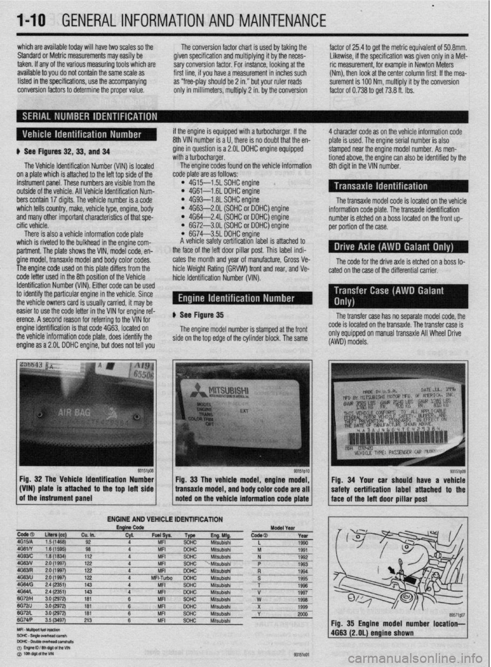
b See Figures 32,33, and 34
The Vehicle Identification Number (VIN) is located
on a plate which is attached to the left top side of the
instrument panel. These numbers are visible from the
outside of the vehicle. All Vehicle Identification Num-
bers contain 17 digits. The vehicle number is a code
which tells country, make, vehicle type, engine, body
and many other important characteristics of that spe-
cific vehicle.
There is also a vehicle information code plate
which is riveted to the bulkhead in the engine com-
partment. The plate shows the VIN, model code, en-
gine model, transaxle model and body color codes.
The engine code used on this plate differs from the
code letter used in the 8th position of the Vehicle
Identification Number (VIN). Either code can be used
to identify the particular engine in the vehicle. Since
the vehicle owners card is usually carried, it may be if the engine is equipped with a turbocharger. If the
8th VIN number is a U, there is no doubt that the en-
gine in question is a 2.OL DOHC engine equipped
with a turbocharger.
The engine codes found on the vehicle information
code plate are as follows:
l 4G15--1.5L SOHC engine l 4G61-1.6L DOHC engine l 4G93-1.8L SOHC engine l 4G63-2.OL (SOHC or DOHC) engine l 4G64-2.4L (SOHC or DOHC) engine l 6G72-3.OL (SOHC or DOHC) engine l 6G74-3.5L DOHC engine
A vehicle safety certification label is attached to
the face of the left door pillar post. This label indi-
cates the month and year of manufacture, Gross Ve-
hicle Weight Rating (GRVW) front and rear, and Ve-
hicle Identification Number (VIM). 4 character code as on the vehicle information code
plate is used. The engine serial number is also
stamped near the engine model number. As men-
tioned above, the engine can also be identified by the
8th digit in the VIN number.
The transaxle model code is located on the vehicle
information code plate. The transaxle identification
number is etched on a boss located on the front up-
per portion of the case.
The code for the drive axle is etched on a boss lo-
cated on the case of the differential carrier.
easier to use the code letter in the VIN for engine ref-
erence. A second reason for referring to the VIN for
engine identification is that code 4663, located on
the vehicle information code plate, does identify the
engine as a 2.OL DOHC engine, but does not tell you ) See Figure 35
The engine model number is stamped at the front
side on the top edge of the cylinder block. The same
Fig. 32 The Vehicle Identification Number
g3’51p’o of the instrument panel _I:^1 / Fig. 33 The vehicle model, engine model,
(VIN) plate is attached to the top left side
bansaxle model, and body color code are all
noted on the vehicle information code plate
ENGINE AND VEHiCLE IDENTlFlCATlON
EnglnCode
ModelYerr
todeal
LIten (cc)
Cu. In. W. Fuel+ Type m.hWg. Code@ Year ,G15JA 1.5 (1468) 92 4 MFI SOHC Mitsubishi
L 1990
IG61N 1.6(15QQ) 98 4 MFI DOHC
Mitsubishi M 1991
1G93lC 1.8 (1834) 112 4 MFI SOHC Mitsubishi N 1992
IG63N 2.0 (1997) 122 4 MFI SOHC “-Mitsubishi P
1993
!G63Fi 2.0 (1997) 122 4 MFI DOHC Mitsubishi
R 1994
,G63iU 2.0 (1997) 122 4 MFI-Tuibo DOHC Mitsubishi
S 1995
.GMffi 2.4 (2351) 143 4 MFI SOHC
Mitsubishi T 1996
iG64L 2.4 (2351) 143 4 MFI DOHC Mitsubishi V
lEzH 3.0 1997
(2972) 161 6 MFI SOHC Mitsubishi W 1998
;G7ZJ 3.0 (2Q72) 161 6 MFI GQHC Mitsubishi
~.. X 1999
iG7zL 3.0 (2972) 181
~ 6 MFI SOHC ___-___ Miisubishi
Y 2000
iG74lP 3.5 (3497) 213 6 MFI SOHC Miisubishi
The transfer case has no separate model code, the
code is located on the transaxle. The transfer case is
onlv eoUiODed on manual transaxle All Wheel Drive
(AWD)‘mbdels.
Fig. 34 Your car should have a vehicle
Fig. 35 Engine model number location-
4663 (2.OL) engine shown
Page 32 of 408
GENERALINFORMATIONAND MAINTENANC-E 1133
Used fluids such as engine oil, transaxle fluid, an-
tifreeze and brake fluid are hazardous wastes and
must be disposed of properly. Before draining any
fluids, consult with your local authorities; in many ar-
eas, waste oil, antifreeze, etc. is being accepted as a
part of recycling programs. A number of service sta-
tions and auto parts stores are also accepting waste
fluids for recycling.
Be sure of the recycling center’s policies before
draining any fluids, as many will not accept different
fluids that have been mixed together.
ENGINE OIL
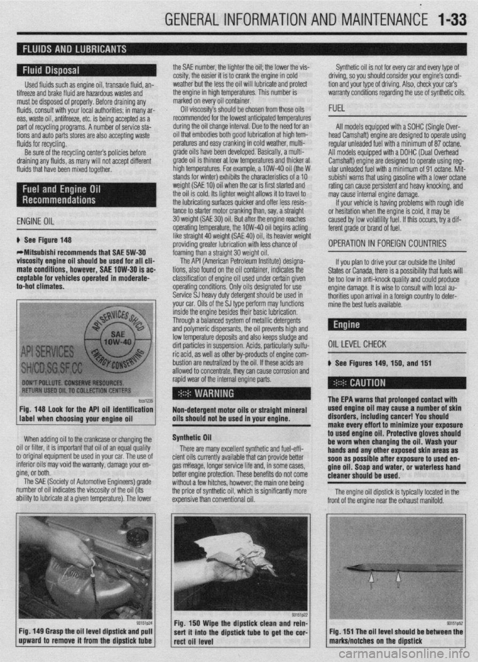
6 See Figure 148
WMitsubishi recommends that SAE 5W-30
viscosity engine oil should be used for all clia
mate conditions, however, SAE low-30 is ac
ceptable for vehicles operated in moderate-
to-hot climates. the SAE number, the lighter the oil; the lower the vis-
cosity, the easier it is to crank the engine in cold
weather but the less the oil will lubricate and protect
the engine in high temperatures. This number is
marked on every oil container.
Oil viscosity’s should be chosen from those oils
recommended for the lowest anticipated temperatures
during the oil change interval. Due to the need for an
oil that embodies both good lubrication at high tem-
peratures and easy cranking in cold weather, multi-
grade oils have been developed. Basically, a multi-
grade oil is thinner at low temperatures and thicker at
high temperatures. For example, a low-40 oil (the W
stands for winter) exhibits the characteristics of a 10
weight (SAE 10) oil when the car is first started and
the oil is cold. Its lighter weight allows it to travel to
the lubricating surfaces quicker and offer less resis-
tance to starter motor cranking than, say, a straight
30 weight (SAE 30) oil. But atier the ensine reaches
operating temperature, the low-40 oil begins acting
like straight 40 weight (SAE 40) oil, its heavier weight
providing greater lubrication with less chance of
foaming than a straight 30 weight oil. Synthetic oil is not for every car and every type of
driving, so you should consider your engine’s condi-
tion and your type of driving. Also, check your car’s
warranty conditions regarding the use of synthetic oils.
FUEL
All models equipped with a SOHC (Single Over-
head Camshaft) engine are designed to operate using
regular unleaded fuel with a minimum of 87 octane.
All models equipped with a DOHC (Dual Overhead
Camshaft) engine are designed to operate using reg-
ular unleaded fuel with a minimum of 91 octane. Mit-
subishi warns that using gasoline with a lower octane
rating can cause persistent and heavy knocking, and
may cause internal engine damage.
If your vehicle is having problems with rough idle
or hesitation when the enoine is cold, it mav be
caused by low volatility fuel. If this occurs, iry a dif-
ferent grade or brand of fuel.
'OPERATION 1~ FOREIGN COUNTRIES
lccS1235 Fig. 148 look for the API oil identification
Non-detergent motor oils or straight mineral
label when choosing your enaine oil oils should not be used in your engine.
When adding oil to the crankcase or changing the
0 Nil or filter, it is important that oil of an equal quality
I original equipment be used in your car. The use of
. tc mtenor 011s may void the warranty, damage your en-
gine, or both. __
The SAE (Society of Automotive Engineers) grade
number of oil indicates the viscosity of the oil (its
ability to lubricate at a given temperature). The lower
Fig. 149 Grasp the oil level dipstick and pull
upward to remove it from the dipstick
tube
The API (American Petroleum Institute) designa-
tions, also found on the oil container, indicates the
classification of engine oil used under certain given
operating conditions. Only oils designated for use
Service SJ heavy duty detergent should be used in
your car. Oils of the SJ type perform may functions If you plan to drive your car outside the United
States or Canada, there is a possibility that fuels will
be too low in anti-knock quality and could produce
engine damage. It is wise to consult with local au-
thorities upon arrival in a foreign country to deter-
mine the best fuels available.
inside the engine besides their basic lubrication.
Through a balanced system of metallic detergents
and polymeric dispersants, the oil prevents high and
low temperature deposits and also keeps sludge and
dirt particles in suspension. Acids, particularly sulfu-
OILLEVELCHECK ric acid, as well as other by-products of engine com-
bustion are neutralized by the oil. If these acids are
# See Figures 149, 150, and 151
allowed to concentrate, thev can cause corrosion and
rapid wear of the internal engine parts.
Synthetic Oil
There are many excellent synthetic and fuel-effi-
cient oils currently available that can provide better
gas mileage, longer service life and, in some cases,
better engine protection. These benefits do not come
without a few hitches, however; the main one being
the price of synthetic oil, which is significantly more
expensive than conventional oil.
.
The EPA warns that urolonoed contact with used engine oil ma; cause-a number of skin
disorders, including cancer! You should
make every effort to minimize your exposure
to
used engine oil. Protective gloves should
be worn when changing the oil. Wash your
hands and any other exposed skin areas as
soon as possible after exposure to used en-
gine oil. Soap and water, or waterless hand
cleaner should be used.
Fig. 150 Wipe the dipstick clean and rein-
sert it into the dipstick
tube to get the cor-
rect oil level The engine oil dipstick is typically located in the
Fig. 151 The oil level should be between the
marks/notches on the dipstick
Page 85 of 408
3-24 ENGINEANDENGINEOVERHAUL
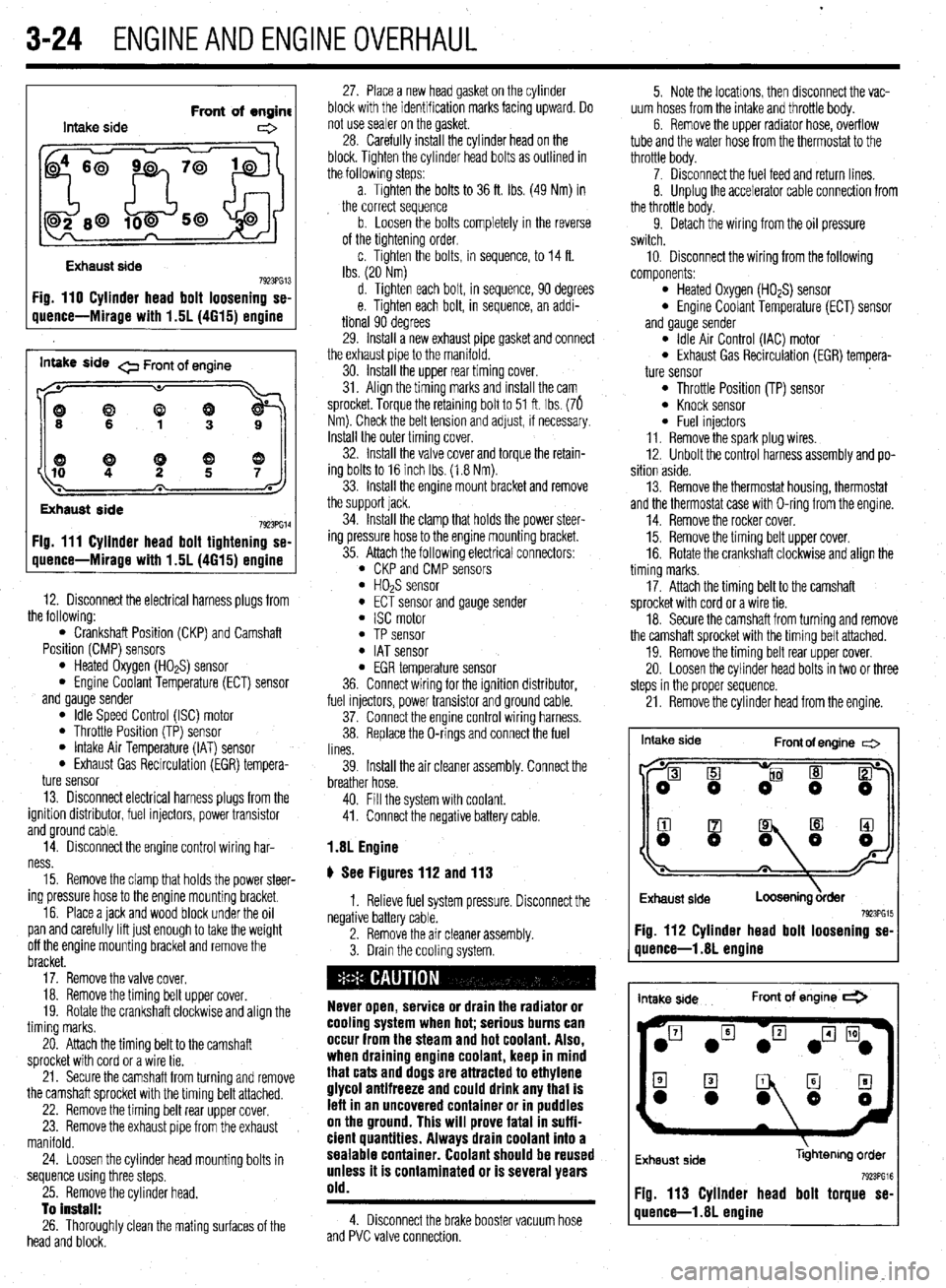
Intake side Front of engine
e
Exhaust side
7923PG13 Fig. 110 Cylinder head bolt loosening se-
uuence-Mirage with 1.5L (4615) ermine
inwe side 0 Front of engine
((9
Exhaust side
7923PG14 Fig. 111 Cyllnder head bolt tightening se-
quence-Mirage with 1.5L (4615) engine
12. Disconnect the electrical harness plugs from
the following:
l Crankshaft Position (CKP) and Camshaft
Position (CMP) sensors
l Heated Oxygen (HO*S) sensor l Engine Coolant Temperature (ECT) sensor
and gauge sender
l Idle Speed Control (ISC) motor l Throttle Position (TP) sensor l Intake Air Temperature (IAT) sensor l Exhaust Gas Recirculation (EGR) tempera-
ture sensor
13. Disconnect electrical harness plugs from the
ignition distributor, fuel injectors, power transistor
and ground cable.
14. Disconnect the engine control wiring har-
ness.
15. Remove the clamp that holds the power steer-
ing pressure hose to the engine mounting bracket.
16. Place a jack and wood block under the oil
pan and carefully lift just enough to take the weight
off the engine mounting bracket and remove the
bracket.
17. Remove the valve cover.
18. Remove the timing belt upper cover.
19. Rotate the crankshaft clockwise and align the
timing marks.
20. Attach the timing belt to the camshaft
sprocket with cord or a wire tie.
21. Secure the camshaft from turning and remove
the camshaft sprocket with the timing belt attached.
22. Remove the timing belt rear upper cover.
23. Remove the exhaust pipe from the exhaust
manifold.
24. Loosen the cylinder head mounting bolts in
sequence using three steps.
25. Remove the cylinder head.
To install:
26. Thoroughly clean the mating surfaces of the
head and block. 27. Place a new head gasket on the cylinder
block with the identification marks facing upward. Do
not use sealer on the gasket.
28. Carefully install the cylinder head on the
block. Tighten the cylinder head bolts as outlined in
the followlng steps:
a. Tighten the bolts to 36 ft. Ibs. (49 Nm) in
the correct sequence
b. Loosen the bolts completely in the reverse
of the tightening order,
c. Tighten the bolts, in sequence, to 14 ft.
Ibs. (20 Nm)
d. Tighten each bolt, in sequence, 90 degrees
e. Tighten each bolt, in sequence, an addi-
tional 90 degrees
29. Install a new exhaust pipe gasket and connect
the exhaust pipe to the manifold.
30. Install the upper rear timing cover.
31. Align the timing marks and install the cam
sprocket. Torque the retaining bolt to 51 ft. Ibs. (76
Nm). Check the belt tension and adjust, if necessary.
Install the outer timing cover.
32. Install the valve cover and torque the retain-
ing bolts to 16 inch Ibs. (1.8 Nm).
33. Install the engine mount bracket and remove
the support jack.
34. Install the clamp that holds the power steer-
ing pressure hose to the engine mounting bracket.
35. Attach the following electrical connectors:
l CKP and CMP sensors l HOPS sensor l ECT sensor and gauge sender l ISC motor l TP sensor l IAT sensor l EGR temperature sensor
36. Connect wiring for the ignition distributor,
fuel injectors, power transistor and ground cable.
37. Connect the engine control wiring harness.
38. Replace the O-rings and connect the fuel
lines.
39. Install the air cleaner assembly. Connect the
breather hose.
40. Fill the system with coolant.
41. Connect the negative battery cable.
1.8L Engine
# See Figures 112 and 113
1. Relieve fuel system pressure. Disconnect the
negative battery cable.
2. Remove the air cleaner assembly.
3. Drain the cooling system.
Never open, service or drain the radiator or
cooling system when hot; serious burns can
occur from the steam and hot coolant. Also,
when draining engine coolant, keep in mind
that cats and dogs are attracted to ethylene
glycol antifreeze and could drink any that is
lefl in an uncovered container or in puddles
on the ground. This will prove fatal in suffi-
cient quantities. Always drain coolant into a
sealable container. Coolant should be reused
unless it is contaminated or is several years
old.
4. Disconnect the brake booster vacuum hose
and PVC valve connection. 5. Note the locations, then disconnect the vac-
uum hoses from the intake and throttle body.
6. Remove the upper radiator hose, overflow
tube and the water hose from the thermostat to the
throttle body.
7. Disconnect the fuel feed and return lines.
8. Unplug the accelerator cable connection from
the throttle body.
9. Detach the wiring from the oil pressure
switch.
10, Disconnect the wiring from the following
components:
l Heated Oxygen (HO*S) sensor l Engine Coolant Temperature (ECT) sensor
and gauge sender
l Idle Air Control (IAC) motor l Exhaust Gas Recirculation (EGR) tempera-
ture sensor
l Throttle Position (TP) sensor l Knock sensor l Fuel injectors
11. Remove the spark plug wires.
12. Unbolt the control harness assembly and po-
sition aside.
13. Remove the thermostat housing, thermostat
and the thermostat case with O-ring from the engine.
14. Remove the rocker cover.
15. Remove the timing belt upper cover.
16. Rotate the crankshaft clockwise and align the
timing marks.
17. Attach the timing belt to the camshaft
sprocket with cord or a wire tie.
18. Secure the camshaft from turning and remove
the camshaft sprocket with the timing belt attached.
19. Remove the timing belt rear upper cover.
20. Loosen the cylinder head bolts in two or three
steps in the proper sequence.
21. Remove the cylinder head from the engine.
Intake side
Front of engine c=>
I
Exhaust side
Loosening &der 7923PG15 Fig. 112 Cylinder head bolt loosening se-
quence-l .8L engine
intake side Front of engine *
Exhaust side libhtenng order
Fig. 113 Cylinder head bolt torque se-
quence-l .8L engine
Page 87 of 408
3-26 ENGINEANDENGINEOVERHAUL
18. Remove the self-locking nuts and the small
retaining bolt holding the exhaust pipe to the bottom
of the exhaust manifold. Separate the pipe from the
manifold and remove the gasket.
19. Remove the bolts holding the support brace
to the bottom of the intake manifold.
20. Use the special hex wrench (MB 998051-01)
and loosen the head bolts in the order shown in 2 or
3 passes. When all are finger loose, remove the bolts.
21. Rock the head gently to break it loose; if tap-
ping is necessary, do so with a rubber or wooden
mallet at the corners of the head. DO NOT pry the
head up by wedging tools between the head and the
block.
22. Lift the head free of the engine. It is coming
off with both manifolds and the intake plenum at-
tached; the help of an assistant is recommended for
lifting. Support the head assembly on wooden blocks
on a suitable workbench. Refer to Cleaning and In-
spection in this section for work to be done before in-
stalling the head. If the head has been removed for
work other than gasket replacement, the rocker as-
sembly and camshaft or other components may be
removed.
Before reinstallation, the head should be com-
pletely assembled on the bench. This allows proper
location and tightening of all the external items.
To install: 23. Place a new gasket on the engine so that the
identifying mark faces up (towards the head) and is at
the timing belt end of the block. Install a new gasket
on the exhaust pipe.
Do not apply sealant to the head gasket or
mating surfaces.
24. Install the head straight down onto the block.
Try to eliminate most of the side-to-side adjust-
ments as this may move the gasket out of position.
Install the bolts by hand and just start each bolt 1 or
2 turns on the threads.
25. The head bolt torque specification is 68 ft.
Ibs. (92 Nm) for a cold engine. The bolts must be
tightened in the order shown in 3 steps. On the first
pass, tighten all the bolts to about 22 ft. Ibs. (30 Nm),
then proceed through the order tightening each bolt
to about 45 ft. Ibs. (61 Nm). The final torque is
achieved on the third pass.
26. Install the intake manifold support brace to
the manifold and tighten the bolts to 16 ft. Ibs. (22
Nm). 27. Making sure the gasket is still in place, con-
nect the exhaust pipe to the base of the exhaust man-
ifold. Use new self-locking nuts; tighten the nuts and
the small bracket bolt to 26 ft. Ibs. (35 Nm).
28. Make sure the camshaft has not changed po-
sition during repalrs. Carefully install the camshaft
sprocket and belt onto the camshaft. Tighten the re-
taining bolt to 66 ft. Ibs. (91 Nm).
29. Install the upper timing belt cover, then
tighten the bolts to 8 ft. Ibs. (11 Nm).
30. Apply sealant to the contact surfaces of the
half-circle plug and install the plug in the head In-
stall the valve cover and gasket.
31. Install the engine mount bracket to the en-
gine. Tighten the mounting nuts and bolts to 42 ft.
Ibs. (57 Nm).
32. Adjust the jack (if necessary) so that the en-
gine mount bushing aligns with the bodywork
bracket. Install the through-bolt and tighten the nuts
snug.
33. Slowly release tension on the floor jack so
that the weight of the engine bears fully on the
mount. Tighten the through-bolt to 52 ft. Ibs. (71
Nm) and the small safety nut to 26 ft. tbs. (36 Nm).
34. Install the bracket holding the power steering
hose and air conditioning hose to the top of the en-
gine mount.
35. Position the control wiring harness and in-
stall the retaining bolts. Attach each electrical con-
nector to its proper location, making sure the wires
are properly routed and firmly connected.
36. Install the spark plug wires in the distributor
cap.
37. Connect the PCV hose and the vacuum
hose(s).
38. Connect the fuel return line. Connect the
brake booster vacuum hose.
39. Install the heater hose, the coolant by-pass
hose and.the upper radiator hose. Pay close attention
to the position and routing of these hoses and insure
that they are not crimped or constricted. Install the
clamps in the same location as before removal.
40. Install a new O-ring on the high pressure fuel
line and lubricate it with a coating of gasoline. Care-
fully connect the high pressure fuel line to the fuel
rail, taking care not to damage the O-ring. Tighten the
bolts only to 4 ft. Ibs. (6 Nm).
41. Connect the accelerator cable and adjust it as
necessary.
42. Install the air intake hose.
43. Fill the cooling system with coolant.
44. Changing the oil and filter is recommended
to eliminate pollutants in the oil.
Intake side
I Front of
engine
Exhaust side
Fig. 116 Cylinder head bolt removal se-
quence-l .6L and 2.OL DDHC engines intake
side
Front of
entine
Exhaust side 7923PG18
Fig. 117 Cylinder head bolt torque se-
quence-l .6L and 2.OL DDHC engines Operating the engine without the proper
amount and type of engine oil will result in
severe engine damage.
45. Connect the negative battery cable.
46. Start the engine and check for leaks of fuel,
vacuum or oil.
47. Check the operation of all engine electrical
systems as well as dashboard gauges and lights.
48. Perform necessary adjustments to the accel-
erator cable, drive belts and engine specifications.
Adjust the coolant level after the engine has cooled
Off.
1.6L and 2.OL DDHC Engines
ti See Figures 116,117, and 116
1. Relieve fuel system pressure.
2. Disconnect the negative battery cable.
3. Drain the cooling system.
Never open, service or drain the radiator or
cooling system when hot; serious burns can
occur from the steam and hot coolant. Also,
when draining engine coolant, keep in mind
that cats and dogs are attracted to ethylene
glycol antifreeze and could drink any that is
left in an uncovered container or in puddles
on the ground. This will prove fatal in suffi-
cient quantities. Always drain coolant into a
sealable container. Coolant should be reused
unless it is contaminated or is several years
old.
4. Disconnect the accelerator cable. There will
be 2 cables if equipped with cruise-control.
5. Remove the air cleaner with the air intake
hose.
6. Detach the electrical connectors from the the
oxygen sensor, engine coolant temperature sensor,
the engine coolant temperature gauge unit and the
engine coolant temperature switch on vehicles with
air conditioning.
7. Disconnect the wiring from the ISC motor,
throttle position sensor, crankshaft angle sensor, fuel
injectors, ignition coil, power transistor, noise filter,
knock sensor on turbocharged engines, EGR temper-
ature sensor (California vehicles), ground cable and
engine control wiring harness.
Painted mark Painted mark
Fig. 116 To ensure that the bolts are tight-
ened exactly 160 total degrees, mark the
11.6L and 2.OL DDHC engines head bolt and cylinder head as shown-
Page 92 of 408
ENGINEANDENGINEOVERHAUL 3-31
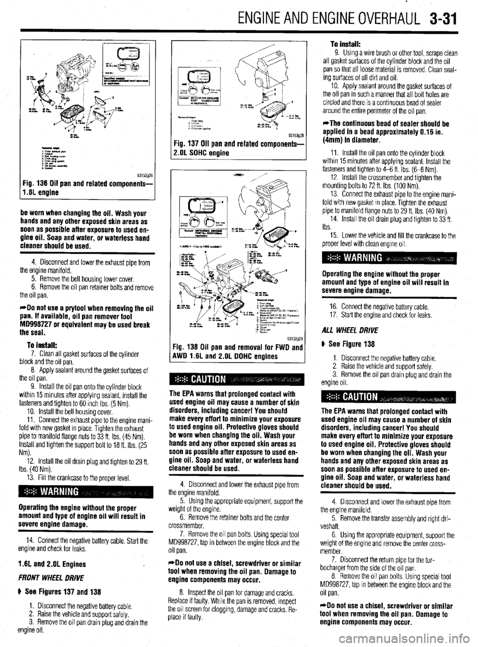
I,.s; engine g3i53g26
Fig 136 Oil pan and related components-
be worn when changing the oil. Wash your
hands and any other exposed skin areas as
soon as possible after exposure to used en-
gine oil. Soap and water, or waterless hand
cleaner should be used.
4. Disconnect and lower the exhaust pipe from
the engine manifold.
5. Remove the bell housing lower cover.
6. Remove the oil pan retainer bolts and remove
the oil pan.
*Do not use a prytool when removing the oil
pan. If available, oil pan remover tool
MD998727 or equivalent may be used break
the seal.
To install:
7. Clean all gasket surfaces of the cylinder
block and the oil pan.
8. Apply sealant around the gasket surfaces of
the oil pan.
9. Install the oil pan onto the cylinder block
within 15 minutes after applying sealant. Install the
fasteners and tighten to 60 inch Ibs. (5 Nm).
10. install the bell housing cover.
11. Connect the exhaust pipe to the engine mani-
fold with new gasket in place. Tighten the exhaust
pipe to manifold flange nuts to 33 ft. Ibs. (45 Nm).
Install and tighten the support bolt to 18 ft. Ibs. (25
Nm).
12. Install the oil drain plug and tighten to 29 ft.
Ibs. (40 Nm).
13. Fill the crankcase to the proper level.
Operating the engine without the proper
amount and type of engine oil will result in
severe engine damage.
14. Connect the negative battery cable. Start the
engine and check for leaks.
1.6L and 2.OL Engines
FRONT WHEEL DRIVE
ti See Figures 137 and 138
1. Disconnect the negative battery cable.
2. Raise the vehicle and support safely.
3. Remove the oil pan drain plug and drain the
engine oil.
93153gza Fig. 137 Oil pan and related components-
2.OL SOHC engine
93153g29 Fig. 138 Oil pan and removal for FWD and
AWD l.liL and 2.OL DDHC enoines
The EPA warns that prolonged contact with
used engine oil may cause a number of skin
disorders, including cancer! You should
make every effort to minimize your exposure
to used engine oil. Protective gloves should
be worn when changing the oil. Wash your
hands and any other exposed skin areas as
soon as possible after exposure to used en-
gine oil. Soap and water, or waterless hand
cleaner should be used.
4. Disconnect and lower the exhaust pipe from
the engine manifold.
5. Using the appropriate equipment, support the
weight of the engine.
6. Remove the retainer bolts and the center
crossmember,
7. Remove the oil pan bolts. Using special tool
MD998727, tap in between the engine block and the
oil pan.
*Do not use a chisel, screwdriver or similar
tool when removing the oil pan. Damage to
engine components may occur.
8. Inspect the oil pan for damage and cracks.
Replace if faulty. While the pan is removed, inspect
the oil screen for clogging, damage and cracks. Re-
place if faulty.
To install: 9. Using a wire brush or other tool, scrape clean
all gasket surfaces of the cylinder block and the oil
pan so that all loose material is removed. Clean seal-
ing surfaces of all dirt and oil.
10. Apply sealant around the gasket surfaces of
the oil pan in such a manner that all bolt holes are
circled and there is a continuous bead of sealer
around the entire perimeter of the oil pan.
*The continuous bead of sealer should be
applied in a bead approximately 0.16 in.
(4mm) in diameter.
11. Install the oil pan onto the cylinder block
within 15 minutes after applying sealant. Install the
fasteners and tighten to 4-6 ft. Ibs. (G8 Nm).
12. Install the crossmember and tighten the
mounting bolts to 72 ft. Ibs. (100 Nm).
13. Connect the exhaust pipe to the engine mani-
fold with new gasket In place. Tighten the exhaust
pipe to manifold flange nuts to 29 ft. Ibs. (40 Nm)
14. Install the oil drain plug and tighten to 33 ft.
Ibs.
15. Lower the vehicle and fill the crankcase to the
proper level with clean engine oil.
Operating the engine without the proper
amount and type of engine oil will result in
severe engine damage.
16. Connect the negative battery cable.
17. Start the engine and check for leaks.
ALL WHEEL DRIVE
ti See Figure 138
1. Disconnect the negative battery cable.
2. Raise the vehicle and support safely.
3. Remove the oil pan drain plug and drain the
engine oil.
The EPA warns that prolonged contact with
used engine oil may cause a number of skin
disorders, including cancer! You should
make every effort to minimize your exposure
to used engine oil. Protective gloves should
be worn when changing the oil. Wash your
hands and any other exposed skin areas as
soon as possible after exposure to used en-
gine oil. Soap and water, or waterless hand
cleaner should be used.
4. Disconnect and lower the exhaust pipe from
the engine manifold.
5. Remove the transfer assembly and right dri-
veshaft.
6. Using the appropriate equipment, support the
weight of the engine and remove the center cross-
member.
7. Disconnect the return pipe for the tur-
bocharger from the side of the oil pan.
8. Remove the oil pan bolts. Using special tool
MD998727, tap In between the engine block and the
oil pan.
*Do not use a chisel, screwdriver or similar
tool when removing the oil pan. Damage to
engine components may occur.
Page 95 of 408
3-34 ENGINEANDENGINEOVERHAUL
9. Remove the front cover mounting bolts. Note
the lengths of the mounting bolts as they are re-
moved for proper installation.
10. Remove the front case assembly and oil
pump assembly.
11. Remove the oil pump cover.
12. Remove the inner and outer gears from the
front case.
To install 13. Remove all gasket material from the mating
surfaces and clean all parts.
14. Thoroughly coat both oil pump gears with
clean engine oil and install them in the correct direc-
tion of rotation.
15. Install the pump cover and tighten the bolts to
84 inch Ibs. (10 Nm).
16. Coat the relief valve and spring with clean en-
gine oil. Install them and tighten the plug to 33 ft.
Ibs. (45 Nm).
17. Install a new front crankshaft seal and coat
the lips of the seal with clean engine oil.
18. Install the front case and oil pump assembly
to the engine block using a new gasket. Tighten the
bolts to loft. Ibs. (14 Nm)
19. Install the oil screen with new gasket. Torque
the screen bolts to 14 ft. Ibs. (19 Nm).
20. Install the oil pan.
21. Install the crankshaft sprocket and timing
belt. Refer to the timing belt procedure in this sec-
tion.
22. Fill the crankcase to the proper level.
Operating the engine without the proper
amount and type of engine oil will result in
severe enoine damaae.
23. Connect the negative battery cable.
1.6L, 2.OL and 2.4L Engines
p See Figures 146, 147, 148, and 149
*Whenever the oil pump is disassembled or
the cover removed, the gear cavity must be
filled with petroleum jelly to seal the pump
and act as a prime. Do not use grease.
1. Disconnect the negative battery cable.
2. Rotate the engine so No. 1 cylinder is on Top
Dead Center (TDC) of its compression stroke.
3. Drain the engine oil.
The EPA warns that prolonged contact with
used engine oil may cause a number of skin
disorders, including cancer! You should
make every effort to minimize your exposure
to used engine oil. Protective gloves should
be worn when changing the oil. Wash your
hands and any other exposed skin areas as
soon as possible afler exposure to used en-
gine oil. Soap and water, or waterless hand
cleaner should be used.
4 Using the proper equipment, support the
weight of the engine Remove the front engine mount
bracket and accessory drive belts.
5 Remove timing belt upper and lower covers.
6. Remove the timing belt and crankshaft
sprocket. Refer to the timing belt procedure in this
section. 7. Detach the electrical connector from the oil
pressure sending unit and remove the oil pressure
sensor. Remove the oil filter and the oil filter bracket.
8. Remove the oil pan, oil screen and gasket.
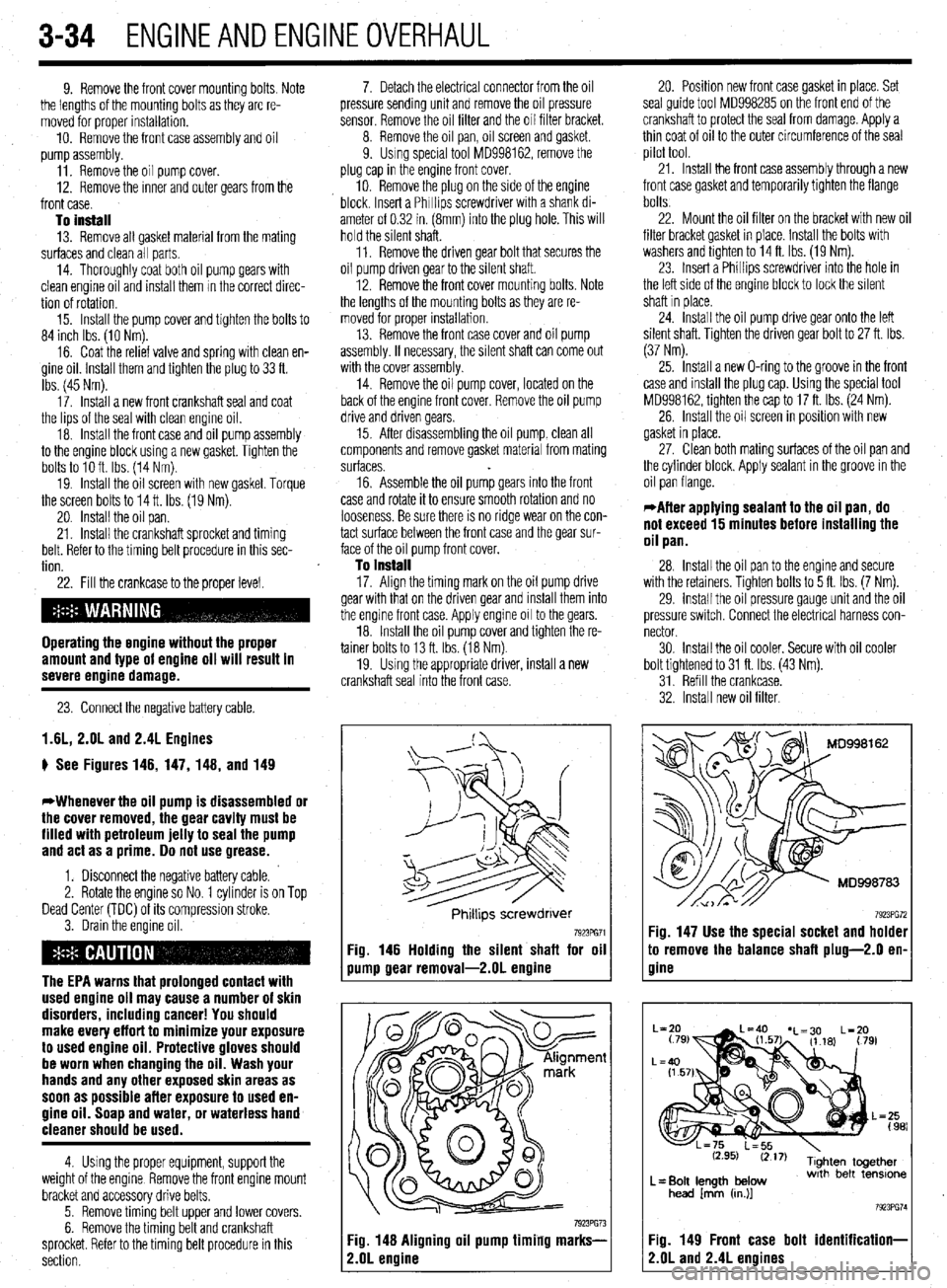
9. Using special tool MD998162, remove the
plug cap in the engine front cover.
10. Remove the plug on the side of the engine
block. Insert a Phrllips screwdriver with a shank di-
ameter of 0.32 in. (8mm) into the plug hole. This will
hold the silent shaft.
11. Remove the driven gear bolt that secures the
oil pump driven gear to the silent shaft.
12. Remove the front cover mounting bolts. Note
the lengths of the mounting bolts as they are re-
moved for proper installation.
13. Remove the front case cover and oil pump
assembly. If necessary, the silent shaft can come out
with the cover assembly.
14. Remove the oil pump cover, located on the
back of the engine front cover. Remove the oil pump
drive and driven gears.
15. After disassembling the oil pump, clean all
components and remove gasket material from mating
surfaces.
16. Assemble the oil pump gears into the front
case and rotate it to ensure smooth rotation and no
looseness. Be sure there is no ridge wear on the con-
tact surface between the front case and the gear sur-
face of the oil pump front cover.
To install 17. Align the timing mark on the oil pump drive
gear with that on the driven gear and install them into
the engine front case. Apply engine 011 to the gears.
18. Install the oil pump cover and tighten the re-
tainer bolts to 13 ft. Ibs. (18 Nm).
19. Using the appropriate driver, install a new
crankshaft seal into the front case.
Phrllips screwdrrver
7923PG71 Fig. 146 Holding the silent shaft for oil
pump gear removal-2.01 engine
7923PG73 Fig. 148 Aligning oil pump timing marks-
2.OL ermine
20. Position new front case gasket in place. Set
seal guide tool MD998285 on the front end of the
crankshaft to protect the seal from damage. Apply a
thin coat of oil to the outer circumference of the seal
pilot tool.
21. Install the front case assembly through a new
front case gasket and temporarily tighten the flange
bolts.
22. Mount the oil filter on the bracket with new oil
filter bracket gasket in place. Install the bolts with
washers and tighten to 14 ft. Ibs. (19 Nm).
23. Insert a Phillips screwdriver into the hole in
the left side of the engine block to lock the silent
shaft in place.
24. Install the oil pump drive gear onto the left
silent shaft. Tighten the driven gear bolt to 27 ft. Ibs.
(37 Nm).
25. Install a new O-ring to the groove in the front
case and install the plug cap. Using the special tool
MD998162, tighten the cap to 17 ft. Ibs. (24 Nm).
26. Install the oil screen in position with new
gasket in place.
27. Clean both mating surfaces of the oil pan and
the cylinder block. Apply sealant In the groove in the
oil pan flange.
*After applying sealant to the oil pan, do
not exceed 15 minutes before installing the
oil pan.
28. Install the oil pan to the engine and secure
with the retainers. Tighten bolts to 5 ft. Ibs. (7 Nm).
29. install the oil pressure gauge unit and the oil
pressure switch. Connect the electrical harness con-
nector.
30. Install the oil cooler. Secure with oil cooler
bolt tightened to 31 ft. Ibs (43 Nm).
31. Refill the crankcase.
32. Install new oil filter.
7923PG72 Fig. 147 Use the special socket and holder
:o remove the balance shaft plug-2.0 en-
7ine
L= Bolt length below
head /mm (cn.)]
Fig. 149 Front case bolt identification-
?.OL and 2.4L engines
Page 97 of 408
3-36 ENGINEANDENGINEOVERHAUL
The EPA warns that urolonaed contact with
used engine oil may cause”a number of skin
disorders, including cancer! You should
make every effort to minimize your exposure
to
used engine oil. Protective gloves should
be worn when changing the oil. Wash your
hands and any other exposed skin areas as
soon as possible after exposure to
used en-
gine oil. Soap and water, or waterless hand
cleaner should be used.
4. Remove the solash shield from the wheel
93153p65 93153p60 well.
5. Remove the oil filter adapter.
6. Remove the lower and upper oil pans.
7. Remove the lower baffle, oil pump pick-up
and upper baffle.
8. Remove the oil pump case mounting bolts
and the oil pump case.
9. Remove the oil pump gear cover.
10. Make matchmarks on the oil pump rotors be-
fore removing them.
,,. r.-- -IL- -.( -L.11---‘I --. IL- -.I _ --
nemove me cranksnarr sear rrom me 011 pump
case.
To instell:
12. Install a new crankshaft seal in the oil pump
cover.
13. Apply engine oil to the rotors, then align the
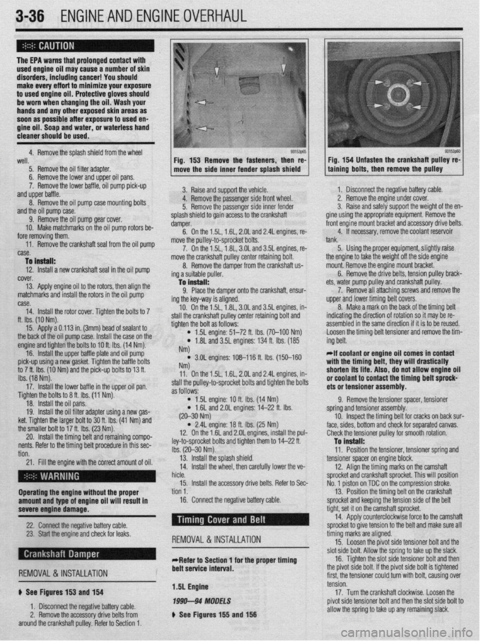
matchmarks and install the rotors in the oil pump Fig. 153 Remove the fasteners, then re-
move the side inner fender splash shield
3. Raise and support the vehicle.
4. Remove the passenger side front wheel.
5. Remove the passenger side inner fender
splash shield to gain access to the crankshaft
damper.
6. On the 1.5L, 1.6L, 2.OL and 2.4L engines, re-
move the oullev-to-sorocket bolts.
7. On thei .5L, i .8L, 3.OL and 3.5L engines, re-
move the crankshaft pulley center retaining bolt.
8. Remove the damper from the crankshaft us
ing a suitable puller.
-la install:
9. Place the damper onto the crankshaft, ensur-
ing the key-way is aligned.
10. On the 1.5L, 1.8L, 3.OL and 3.5L engines, in-
e crankshaft pulley center retaining bolt and
the bolt as follows: Fig. 154 Unfasten the crankshaft pulley re-
talning bolts, then remove the pulley
case.
14. Install the rotor cover. Tighten the bolts to 7
ft. Ibs. (10 Nm).
15. Apply a 0.113 in. (3mm) bead of sealant to
the back of the oil pump case. I[ -‘-‘I IL -~-- IL-
nsrall me ca
se on me engine and tighten the bolts to IOft Ihc 11 ,,, -. , .4 Nm).
16. Install the upper baffle r tlal te and oil pump
pick-up using a new gasket. Tic fhtti,, ,,lG va,,,ti ““a,., an tha hafflc, hnltc to 7 ft. Ibs. (10 Nm) and the pit k-up bolts to 13 ft.
Ibs. (18 Nm).
17. Install the lower baffle in the upper oil pan.
Tighten the bolts to 8 ft. Ibs. (11 Nm).
18. Install the oil pans.
19. Install the oil filter adapter using a new gas-
ket. Tighten the larger bolt to 30 ft. Ibs. (41 Nm) and
the smaller bolt to 1’ u ‘L- Inn ‘I--’ stall thl
tighten
4
) 1.5L engine: 51-72 ft. Ibs. (70-100 Nm)
l 1.8L and 3.5L engines: 134 ft. Ibs. (185
NM
l 3.OL engines: 108-116 ft. lbs. (150-160 NW 11. On the 1.5L, 1.6L, 2.OL and 2.4L engines, in-
stall the pulley-to-sprocket bolts and tighten the bolts
as follows:
l 1.5L engine: 10 ft. Ibs. (14 Nm)
* 1.6L and 2.OL engines: 14-22 ft. Ibs. 1. Disconnect the negative battery cable.
2. Remove the engine under cover.
3. Raise and safely support the weight of the en-
gine using the appropriate equipment. Remove the
front engine mount bracket and accessory drive belts.
4. If necessary, remove the coolant reservoir
tank.
5. Using the proper equipment, slightly raise
ets, water pump pulley
7. Remove all attr
upper and lower timin{
8. Make a mark o
indicating the directior
assembled in the same the engine to take the weight off the side engine
mount. Remove the engine mount bracket.
6. Remove the drive belts, tension pulley brack-
and crankshaft pulley.
aching screws and remove the
J belt covers.
n the back of the timing belt
I of rotation so it may be re-
! direction if it is to be reused.
tensioner and remove the tim-
Loosen the timing belt
ing belt.
*If coolant or engine oil comes in contact
with the timing bplt thaw will r(mcti~~llv Wll L, .,,s,, n,,, u,uu.,vu,,,
shorten its life. A ,IS o, do not allow engine oil
#.I nn..lr”* In rind In,
“I IruuI(IIIL Lu Irulll&t the timing belt sprock-
ets or tensioner assembly.
9. Remove the tensioner spacer, tensioner
spring and tensioner assembly.
cracks on back sur-
;eoarated canvas.
20. Install the tilllIllY uljllOllu IclllallllllY ~ullIPV-
:
nents. Refer to the timing belt procedure in this sec-
: tion.
21. Fill the engine with the correct amount of oil.
I . (20-30 Nm)
l 2.4L engine: 18 ft. Ibs. (25 Nm)
12. On the 1.6L and 2.OL engines, install the pul-
ley-to-sprocket bolts and tighten them to 14-22 ft.
Ibs. (20-30 Nm).
13. Install the splash shield.
14. Install the wheel, then carefully lower the ve- 10. Inspect the timing belt for I
face, sides, bottom and check for ! (
Check the tensioner pulley for smooth rotation.
To install:
11. Position the tensioner, tensioner spring and
tensioner spacer on engine block.
12. Align the timing marks on the camshaft
ft sprocket. This will position
tn the comoression stroke.
I hicle.
sprocket and cranksha
15. Install the accessory drive belts. Refer to Sec-
No. 1 piston on TDC o
Operating the engine without the proper tion 1.
13. Position the timing belt on the crankshaft
amount and type of engine oil will result in 16. Connect the negative battery cable.
sprocket and keeping the tension side of the bolt
severe engine damage.
-
22. -s
Chrmxt the nenntive h;lttm cnhle --, , I” ,.-J XL.._ I -..-., --I.-.
23. Start the engine and check for leaks.
REMOVAL &INSTALLATION
tight, set it on the cam, shaft sprocket.
14. Apply counterc Yockwise force to the camshaft
snrnckd tn nive tensin In -r .__.._. ._ J..- ._ - _ to the belt and make sure all
timing marks are aligned.
15. Loosen the pivot side tensioner bolt and the
clnt
&In hnlt Allnur thn rnrinn tn tdm III-I thn slack, cl then , d I, I’ r),“I 44”” ““IL. “ll”sl LllU .y”“yj L” L”I\U Low Ul” L .-Refer to Section 1 for the proper timing 16. Tighten the slot side tensioner bolt ark
., , , , ,, ,, ,, , , , , ,, . ,, ,~
REMOVAL &INSTALLATION
6 See Figures 153 and 154
1. Disconnect the negative battery cable.
2. Remove the accessory drive belts from
around the crankshaft pulley. Refer to Section 1. belt service interval.
1.5L Engine
1999-94 MODELS
b See Figures 155 and 156 me p~vor sloe DOI~. IT me p~vor sloe OOII
IS ogntened
first, the tensioner could turn with bolt, causing over
tension.
17. Turn the crankshaft clockwise. Loosen the
pivot side tensioner bolt and then the slot side bolt to
allow the spring to take up any remaining slack.
Page 98 of 408
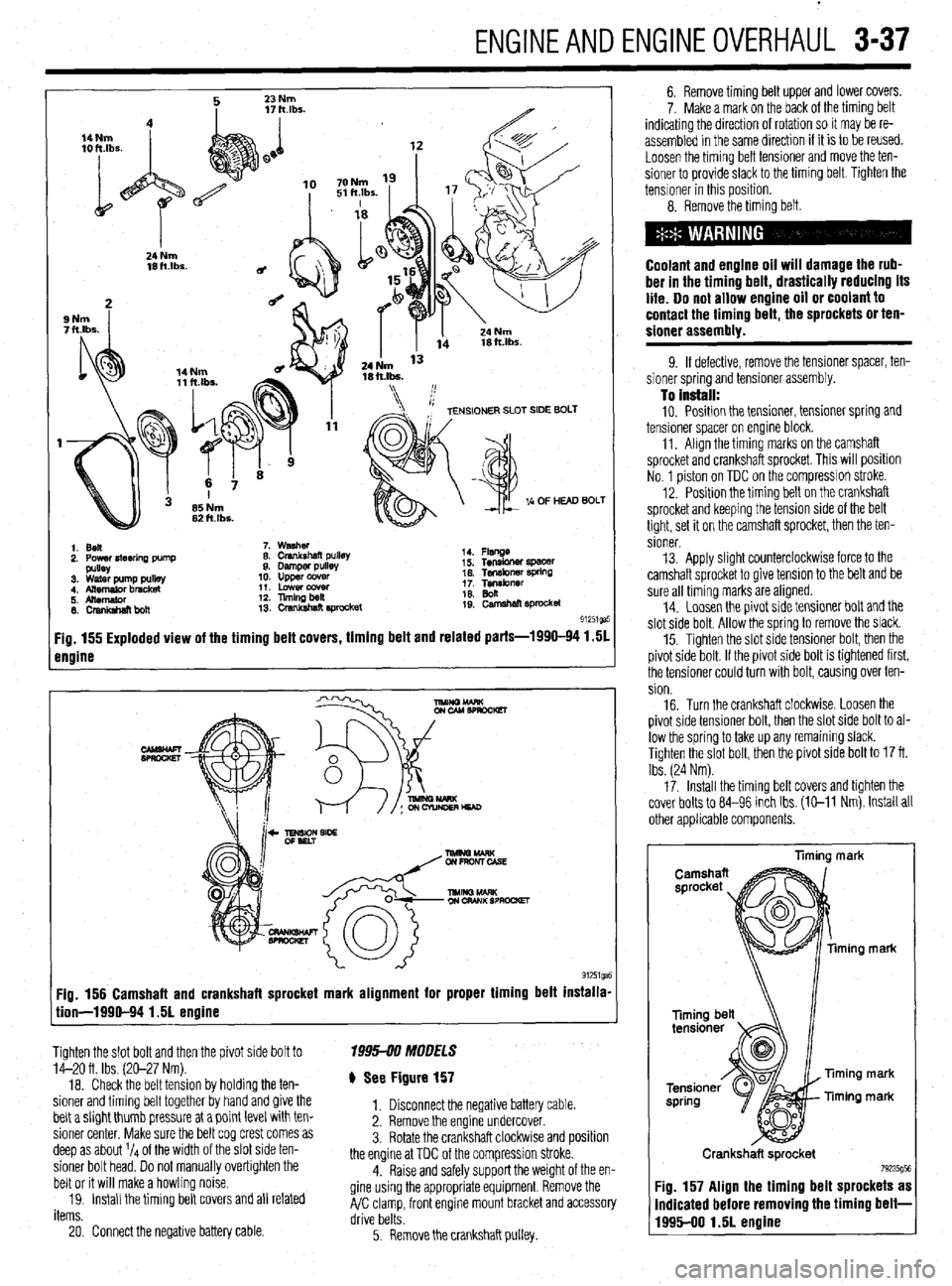
ENGINEANDENGINEOVERHAUL 3-37
1. Ben
2. Power4teerlna Dump 7. washer
8. Crankshaft pullet
9. Damper pulls
10. upper ccwer
11. Lowercowr
12. llmingbeil
13. crsnkshat? E#ocket 14. Flsnge
i 5. Tensbner spacer
16. Tef~kner WkW
1; Tgibnrr
19: camehan sprocket
91251ga
Fig. 155 Exploded view of the timing belt covers, timing belt and related parts-1990-94 1.51
engine
Fig. 156 Camshaft and crankshaft sprocket mark alignment for proper timing belt installa-
tion-1990-94 1.51 engine
Tighten the slot bolt and then the pivot side bolt to
14-20 ft. Ibs. (20-27 Nm).
18. Check the belt tension by holding the ten-
sioner and timing belt together by hand and give the
belt a slight thumb pressure at a point level with ten-
sioner center. Make sure the belt cog crest comes as
deep as about l/4 of the width of the slot side ten-
sioner bolt head. Do not manually overtighten the
belt or it will make a howling noise.
19. Install the timing belt covers and all related
items. 1995-00 MOOFLS
) See Figure 157
1. Disconnect the negative battery cable.
2. Remove the engine undercover.
3. Rotate the crankshaft clockwlse and position
the engine at TDC of the compression stroke.
4. Raise and safely support the weight of the en-
gine using the appropriate equipment. Remove the
A/C clamp, front engine mount bracket and accessory
drive belts.
20. Connect the negative battery cable.
5. Remove the crankshaft pulley. 6. Remove timing belt upper and lower covers.
7. Make a mark on the back of the timing belt
indicating the direction of rotation so it may be re-
assembled in the same direction if it is to be reused.
Loosen the timing belt tensioner and move the ten-
sioner to provide slack to the timing belt. Tighten the
tensioner in this position.
8. Remove the timing belt.
Coolant and engine oil will damage the rub-
ber in the timing belt, drastically reducing its
life. Do not allow engine oil or coolant to
contact the timing belt, the sprockets or ten-
sioner assembly.
9. If defective, remove the tensioner spacer, ten-
sioner spring and tensioner assembly.
To install: 10. Position the tensioner, tensioner spring and
tensioner spacer on engine block.
11. Align the timing marks on the camshaft
sprocket and crankshaft sprocket. This will position
No. 1 piston on TDC on the compression stroke.
12. Position the timing belt on the crankshaft
sprocket and keeping the tension side of the belt
tight, set it on the camshaft sprocket, then the ten-
sioner.
13. Apply slight counterclockwise force to the
camshaft sprocket to give tension to the belt and be
sure all timing marks are aligned.
14. Loosen the pivot side tensioner bolt and the
slot side bolt. Allow the spring to remove the slack.
15. Tighten the slot side tensioner bolt, then the
pivot side bolt. If the pivot side bolt is tightened first,
the tensioner could turn with bolt, causing over ten-
sion.
16. Turn the crankshaft clockwise. Loosen the
pivot side tensioner bolt, then the slot side bolt to al-
low the spring to take up any remaining slack.
Tighten the slot bolt, then the pivot side bolt to 17 ft.
Ibs. (24 Nm).
17. Install the timing belt covers and tighten the
cover bolts to 84-96 inch Ibs. (E-11 Nm). Install all
other applicable components.
liming mark
ming mark
Timing mark
Timing mark
Crankshaft sprocket
79235g5t Fig. 157 Align the timing belt sprockets as
indicated before removing the timing belt-
1995-00 1.51 engine
Page 99 of 408
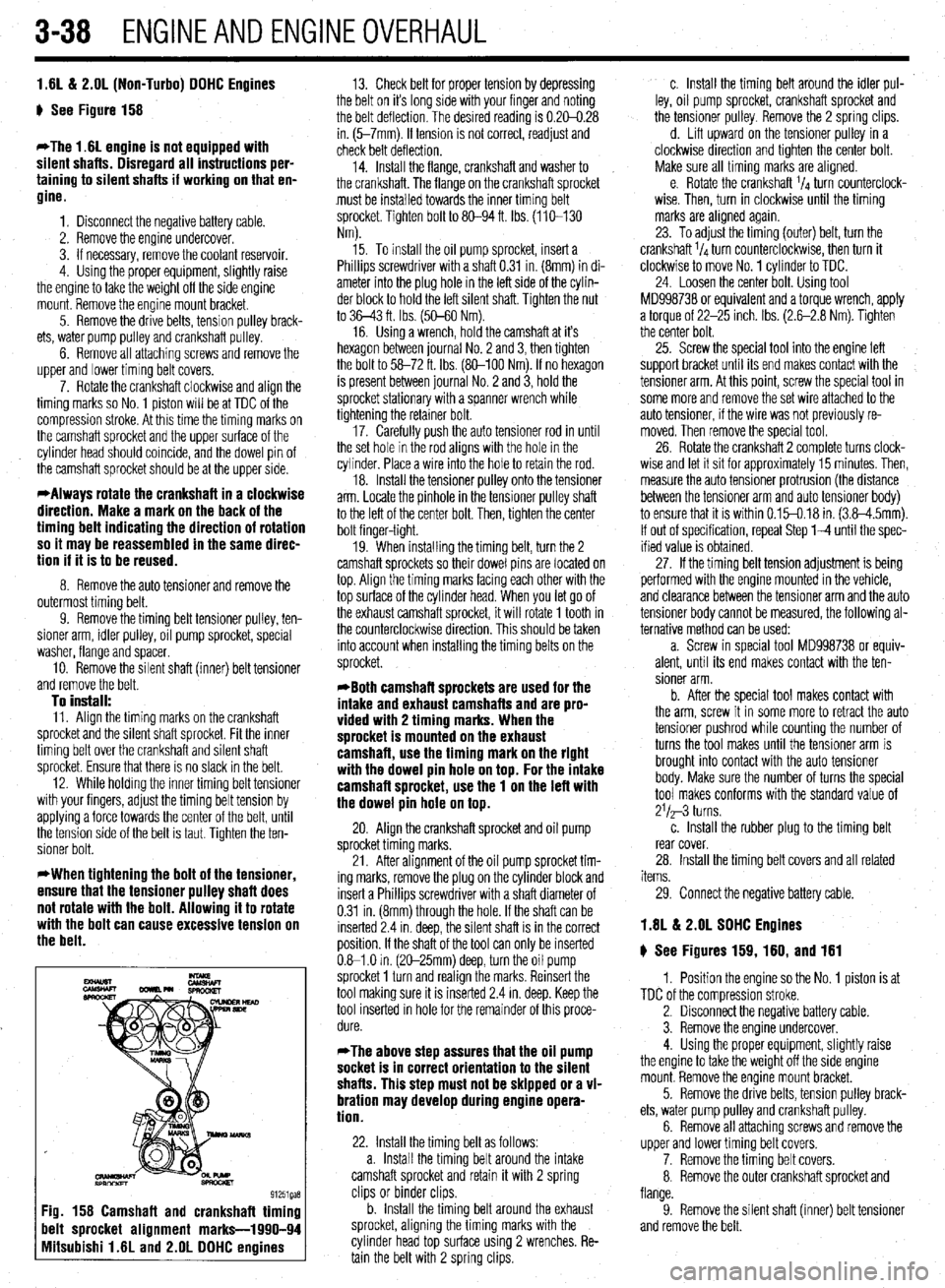
3-38 ENGINEANDENGINEOVERHAUL
1.61&? 2.OL (Non-Turbo) DOHC Engines
g See Figure 158
*The 1.6L engine is not equipped with
silent shafts. Disregard all instructions per-
taining to silent shafts if working on that en-
gine.
1. Disconnect the negative battery cable.
2. Remove the engine undercover.
3. If necessary, remove the coolant reservoir.
4. Using the proper equipment, slightly raise
the engine to take the weight off the side engine
mount. Remove the engine mount bracket.
5. Remove the drive belts, tension pulley brack-
ets, water pump pulley and crankshaft pulley.
6. Remove all attaching screws and remove the
upper and lower timing belt covers.
7. Rotate the crankshaft clockwise and align the
timing marks so No. 1 piston will be at TDC of the
compression stroke. At this time the timing marks on
the camshaft sprocket and the upper surface of the
cylinder head should coincide, and the dowel pin of
the camshaft sprocket should be at the upper side.
*Always rotate the crankshaft in a clockwise
direction. Make a mark on the back of the
timing belt indicating the direction of rotation
so it may be reassembled in the same direc-
tion if it is to be reused.
8. Remove the auto tensioner and remove the
outermost timing belt.
9. Remove the timing belt tensioner pulley, ten-
sioner arm, idler pulley, oil pump sprocket, special
washer, flange and spacer.
10. Remove the silent shaft (inner) belt tensioner
and remove the belt.
To install: 11. Align the timing marks on the crankshaft
sprocket and the silent shaft sprocket. Fit the inner
timing belt over the crankshaft and silent shaft
sprocket. Ensure that there is no slack in the belt.
12. While holding the inner timing belt tensioner
with your fingers, adjust the timing belt tension by
applying a force towards the center of the belt, until
the tension side of the belt is taut. Tighten the ten-
sioner bolt.
*When tightening the bolt of the tensioner,
ensure that the tensioner pulley shaft does
not rotate with the bolt. Allowing it to rotate
with the bolt can cause excessive tension on
the belt.
13. Check belt for proper tension by depressing
the belt on it’s long side with your finger and noting
the belt deflection. The desired reading is 0.20-0.28
in. (5-7mm). If tension is not correct, readjust and
check belt deflection.
14. Install the flange, crankshaft and washer to
the crankshaft. The flange on the crankshaft sprocket
must be installed towards the inner trming belt
sprocket. Tighten bolt to 80-94 ft. Ibs. (110-130
Nm).
15. To install the oil pump sprocket, insert a
Phillips screwdriver with a shaft 0.31 in. (8mm) in di-
ameter into the plug hole in the left side of the cylin-
der block to hold the left silent shaft. Tighten the nut
to 36-43 ft. Ibs. (50-60 Nm).
16. Using a wrench, hold the camshaft at it’s
hexagon between journal No. 2 and 3, then tighten
the bolt to 58-72 ft. Ibs. (80-100 Nm). If no hexagon
is present between journal No. 2 and 3, hold the
sprocket stationary with a spanner wrench while
tightening the retainer bolt.
17. Carefully push the auto tensioner rod in until
the set hole in the rod aligns with the hole in the
cylinder. Place a wire into the hole to retain the rod.
18. Install the tensioner pulley onto the tensioner
arm. Locate the pinhole in the tensioner pulley shaft
to the left of the center bolt. Then, tighten the center
bolt finger-tight.
19. When installing the timing belt, turn the 2
camshaft sprockets so their dowel pins are located on
top. Align the timing marks facing each other with the
top surface of the cylinder head. When you let go of
the exhaust camshaft sprocket, it will rotate 1 tooth in
the counterclockwise direction. This should be taken
into account when installing the timing belts on the
sprocket.
*Both camshaft sprockets are used for the
intake and exhaust camshafts and are pro-
vided with 2 timing marks. When the
sprocket is mounted on the exhaust
camshaft, use the timing mark on the right
with the dowel pin hole on top. For the intake
camshafl sprocket, use the 1 on the left with
the dowel pin hole on top.
20. Align the crankshaft sprocket and oil pump
sprocket timing marks.
21. After alignment of the oil pump sprocket tim-
ing marks, remove the plug on the cylinder block and
insert a Phillips screwdriver with a shaft diameter of
0.31 in. (8mm) through the hole. If the shaft can be
inserted 2.4 in. deep, the silent shaft is in the correct
position. If the shaft of the tool can only be inserted
0.61 .O in. (2C-25mm) deep, turn the oil pump
sprocket 1 turn and realign the marks. Reinsert the
tool making sure it is inserted 2.4 in. deep. Keep the
tool inserted in hole for the remainder of this proce-
dure.
*The above step assures that the oil pump
socket is in correct orientation to the silent
shafts. This step must not be skipped or a vi-
bration may develop during engine opera-
tion.
22. Install the timing belt as follows:
a. Install the timing belt around the intake
camshaft sprocket and retain it with 2 spring
clips or binder clips.
b. Install the timing belt around the exhaust
sprocket, aligning the timing marks with the
cylinder head top surface using 2 wrenches. Re-
tain the belt with 2 spring clips. c. Install the timing belt around the idler pul-
ley, oil pump sprocket, crankshaft sprocket and
the tensioner pulley. Remove the 2 spring clips.
d. Lift upward on the tensioner pulley in a
clockwise direction and tighten the center bolt.
Make sure all timing marks are aligned.
e. Rotate the crankshaft ‘14 turn counterclock-
wise. Then, turn in clockwise until the timing
marks are alrgned again.
23. To adjust the timing (outer) belt, turn the
crankshaft ‘14 turn counterclockwise, then turn it
clockwise to move No. 1 cylinder to TDC.
24. Loosen the center bolt. Using tool
MD998738 or equivalent and a torque wrench, apply
a torque of 22-25 inch. Ibs. (2.6-2.8 Nm). Tighten
the center bolt.
25. Screw the special tool into the engine left
support bracket until its end makes contact with the
tensioner arm. At this point, screw the special tool in
some more and remove the set wire attached to the
auto tensioner, if the wire was not previously re-
moved. Then remove the specral tool.
26. Rotate the crankshaft 2 complete turns clock-
wise and let it sit for approximately 15 minutes. Then,
measure the auto tensioner protrusion (the distance
between the tensioner arm and auto tensioner body)
to ensure that it is within 0.15-0.18 in. (3.8-4.5mm).
If out of specification, repeat Step l-4 until the spec-
ified value is obtained.
27. If the timing belt tension adjustment is being
performed with the engine mounted in the vehicle,
and clearance between the tensioner arm and the auto
tensioner body cannot be measured, the following al-
ternative method can be used:
a. Screw in special tool MD998738 or equiv-
alent, until its end makes contact with the ten-
sioner arm.
b. After the special tool makes contact with
the arm, screw it in some more to retract the auto
tensioner pushrod while counting the number of
turns the tool makes until the tensioner arm is
brought into contact with the auto tensioner
body. Make sure the number of turns the special
tool makes conforms with the standard value of
21/a-3 turns.
c. Install the rubber plug to the timing belt
rear cover.
28. Install the timing belt covers and all related
items.
29. Connect the negative battery cable.
1.8L & 2.OL SOHC Engines
g See Figures 159, 160, and 161
1. Position the engine so the No. 1 piston is at
TDC of the compression stroke.
2. Disconnect the negative battery cable.
3. Remove the engine undercover.
4. Using the proper equipment, slightly raise
the engine to take the weight off the side engine
mount. Remove the engine mount bracket.
5. Remove the drive belts, tension pulley brack-
ets, water pump pulley and crankshaft pulley.
6. Remove all attaching screws and remove the
upper and lower timing belt covers.
7. Remove the timing belt covers.
8. Remove the outer crankshaft sprocket and
flange.
9. Remove the silent shaft (inner) belt tensioner
and remove the belt.