seat adjustment MITSUBISHI DIAMANTE 1900 Repair Manual
[x] Cancel search | Manufacturer: MITSUBISHI, Model Year: 1900, Model line: DIAMANTE, Model: MITSUBISHI DIAMANTE 1900Pages: 408, PDF Size: 71.03 MB
Page 2 of 408
.
1-2 GENERALINFORMATIONAND MAINTENANCE
Chitton’s Total Car Care manual for the 199M10
Mitsubishi Mirage, Galant and Diamante is intended
to help you learn more about the inner workings of
your vehicle while saving you money on its upkeep
and operation.
The beginning of the book will likely be referred to
the most, since that is where you will find information
for maintenance and tune-up. The other sections deal
with the more complex systems of your vehicle. Oper-
ating systems from engine through brakes are cov-
ered to the extent that the average do-it-yourselfer be-
comes mechanically involved. This book will not
explain such things as rebuilding a differential for the
simple reason that the expertise required and the in-
vestment in special tools make this task uneconomi-
cal. It will, however, give you detailed instructions to
help you change your own brake pads and shoes, re-
place spark plugs, and perform many more jobs that
can save you money, give you personal satisfaction
and help you avoid expensive problems.
A secondary purpose of this book is a reference for
owners who want to understand their vehicle and/or
their mechanics better. In this case, no tools at all are
required.
Before removing any bolts, read through the entire
procedure. This will give you the overall view of what
tools and supplies will be required. There is nothing
more frustrating than having to walk to the bus stop
on Monday morning because you were short one bolt
on Sunday afternoon. So read ahead and plan ahead.
Each operation should be approached logically and
all procedures thoroughly understood before attempt-
ing any work.
All sections contain adjustments, maintenance, re-
moval and installation procedures, and in some cases,
repair or overhaul procedures. When repair is not con-
sidered practical, we tell you how to remove the part
and then how to install the new or rebuilt replacement.
In this way, you at least save labor costs. “Backyard”
repair of some components is just not practical.
Many procedures in this book require you to “label
and disconnect. . ” a group of lines, hoses or wires.
Don’t be lulled into thinking you can remember where
everything goes-you won’t. If you hook up vacuum
or fuel lines incorrectly, the vehicle may run poorly, if
at all. If you hook up electrical wiring incorrectly, you
may instantly learn a very expensive lesson.
You don’t need to know the official or engineering
name for each hose or line. A piece of masking tape
on the hose and a piece on its fitting will allow you to
assign your own label such as the letter A or a short name. As long as you remember your own code, the
lines can be reconnected by matching similar letters
or names. Do remember that tape will dissolve in
gasolrne or other fluids; if a component is to be
washed or cleaned, use another method of identifica-
tion. A permanent felt-tipped marker or a metal scribe
can be very handy for marking metal parts. Remove
any tape or paper labels after assembly.
It’s necessary to mention the difference between
maintenance and repair Maintenance includes rou-
tine inspections, adjustments, and replacement of
parts which show signs of normal wear Maintenance
compensates for wear or deterioration. Repair implies
that something has broken or is not working. A need
for repair is often caused by lack of maintenance. Ex-
ample, draining and refilling the automatic transaxle
fluid is maintenance recommended by the manufac-
turer at specific mileage intervals. Failure to do this
can shorten the life of the transmission/transaxle, re-
quiring very expensive repairs. While no maintenance
program can prevent items from breaking or wearing
out, a general rule can be stated: MAINTENANCE IS
CHEAPER THAN REPAIR.
Two basic mechanrc’s rules should be mentioned
here. First, whenever the left side of the vehicle or en-
gine is referred to, it is meant to specify the drivers
side. Conversely, the right side of the vehicle means
the passengers side. Second, screws and bolts are
removed by turning counterclockwise, and tightened
by turning clockwrse unless specifically noted.
Safety is always the most important rule. Con-
stantly be aware of the dangers involved in working
on an automobile and take the proper precautions.
See the informatron in this section regarding SER-
VICING YOUR VEHICLE SAFELY and the SAFETY
NOTICE on the acknowledgment page.
Pay attention to the instructions provided. There
are 3 common mistakes in mechanical work:
1. Incorrect order of assembly, disassembly or
adjustment. When taking something apart or putting
it together, performing steps in the wrong order usu-
ally just costs you extra time; however, it CAN break
something. Read the entire procedure before begin-
ning disassembly. Perform everything in the order in
which the instructions say you should, even if you
can’t immedrately see a reason for it. When you’re
taking apart something that is very intricate, you
might want to draw a picture of how it looks when as-
sembled at one point in order to make sure you get everything back in its proper position. We will supply
exploded views whenever possible. When making
adjustments, perform them in the proper order. One
adjustment possibly will affect another.
2. Overtorquing (or undertorquing). While it is
more common for overtorquing to cause damage,
undertorquing may allow a fastener to vibrate loose
causing serious damage. Especially when dealing
with aluminum parts, pay attention to torque specifi-
cations and utilize a torque wrench in assembly. If a
torque figure is not available, remember that if you
are using the right tool to perform the job, you will
probably not have to strain yourself to get a fastener
tight enough. The pitch of most threads is so slight
that the tension you put on the wrench will be multi-
plied many times in actual force on what you are
tightening. A good example of how critical torque is
can be seen in the case of spark plug installation, es-
pecially where you are putting the plug into an alu-
minum cylinder head. Too little torque can fail to
crush the gasket, causing leakage of combustion
gases and consequent overheating of the plug and
engine parts. Too much torque can damage the
threads or distort the plug, changing the spark gap.
There are many commercial products available for
ensuring that fasteners won’t come loose, even if they
are not torqued just right (a very common brand is
Loctite? If you’re worried
about getting something
together tight enough to hold, but loose enough to
avoid mechanical damage during assembly, one of
these products might offer substantial insurance. Be-
fore choosing a threadlocking compound, read the
label on the package and make sure the product is
compatible with the materials, fluids, etc. involved.
3. Crossthreading. This occurs when a part such
as a bolt is screwed into a nut or casting at the wrong
angle and forced. Crossthreading is more likely to
occur if access is difficult. It helps to clean and lubri-
cate fasteners, then to start threading the bolt, spark
plug, etc. with your fingers If you encounter resis-
tance, unscrew the part and start over again at a dif-
ferent angle until it can be inserted and turned several
times without much effort. Keep in mind that many
parts, especially spark plugs, have tapered threads,
so that gentle turning will automatically bring the part
you’re threading to the proper angle. Don’t put a
wrench on the part until its been tightened a couple
of turns by hand. If you suddenly encounter resis-
tance, and the part has not seated fully, don’t force it.
Pull it back out to make sure it’s clean and threading
properly.
Be sure to take your time and be patient, and al-
ways plan ahead. Allow yourself ample time to per-
form repairs and maintenance You may find main-
taining your car a satisfying and enjoyable
experience.
b See Figures 1 thru 15
Naturally, without the proper tools and equipment
it is impossible to properly service your vehicle. It
would also be virtually impossible
to catalog every
tool that you would need to perform all of the opera-
tions in this book. Of course, It would be unwise for
the amateur to rush out and buy an expensive set of
tools on the theory that he/she may need one or more
of them at some time, The best approach is to proceed slowly, gathering savings will
be far outweighed by frustration and
a good quality set of those tools that are used most mangled knuckles.
frequently Don’t be misled by the low cost of bargain Begin accumulating those tools that are used most
tools. It is far better to spend a little more for better frequently: those associated with routine maintenance
quality. Forged wrenches, 6 or 12-point sockets and and tune-up. In addition to the normal assortment of
fine tooth ratchets are by far preferable to their less screwdrivers and pliers, you should have the follow-
expensive counterparts. As any good mechanic can ing tools:
tell you, there are few worse experiences than trying
l Wrenches/sockets and combination open
to work on a vehicle with bad tools. Your monetary end/box end wrenches in sizes from %-% in. or
Page 130 of 408
ENGINEANDENGINEOVERHAUL 3-69
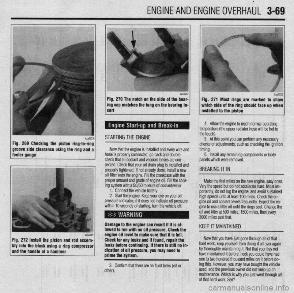
STARTING THE ENGINE
clearance using the ring and a Now that the engine is installed and every wire and
hose is properly connected, go back and double
check that all coolant and vacuum hoses are con-
, netted. Check that your oil drain plug is installed and
tt tl
C ti
hYs3222 Fig. 271 Most rings are marked to show
which side of the ring should face up when
installed to the piston
J
4. Allow the engine to reach normal operating
?mperature (the upper radiator hose will be hot to
ie touch).
5. At this point you can perform any necessary
hecks or adjustments, such as checking the ignition
ming.
6. Install any remaining components or body
anels which were removed.
IREAKING IT IN
Make the first miles on the new engine, easy ones.
arv the soeed but do not accelerate hard. Most im-
oriantly, do not lug the engine, and avoid sustained
igh speeds until at least 100 miles. Check the en-
ine oil and coolant levels frequently. Expect the en-
ine to use a little oil until the rings seat. Change the
il and filter at 500 miles, 1500 miles, then every
Page 298 of 408
SUSPENSION AND STEERiNG 8-3
STUD
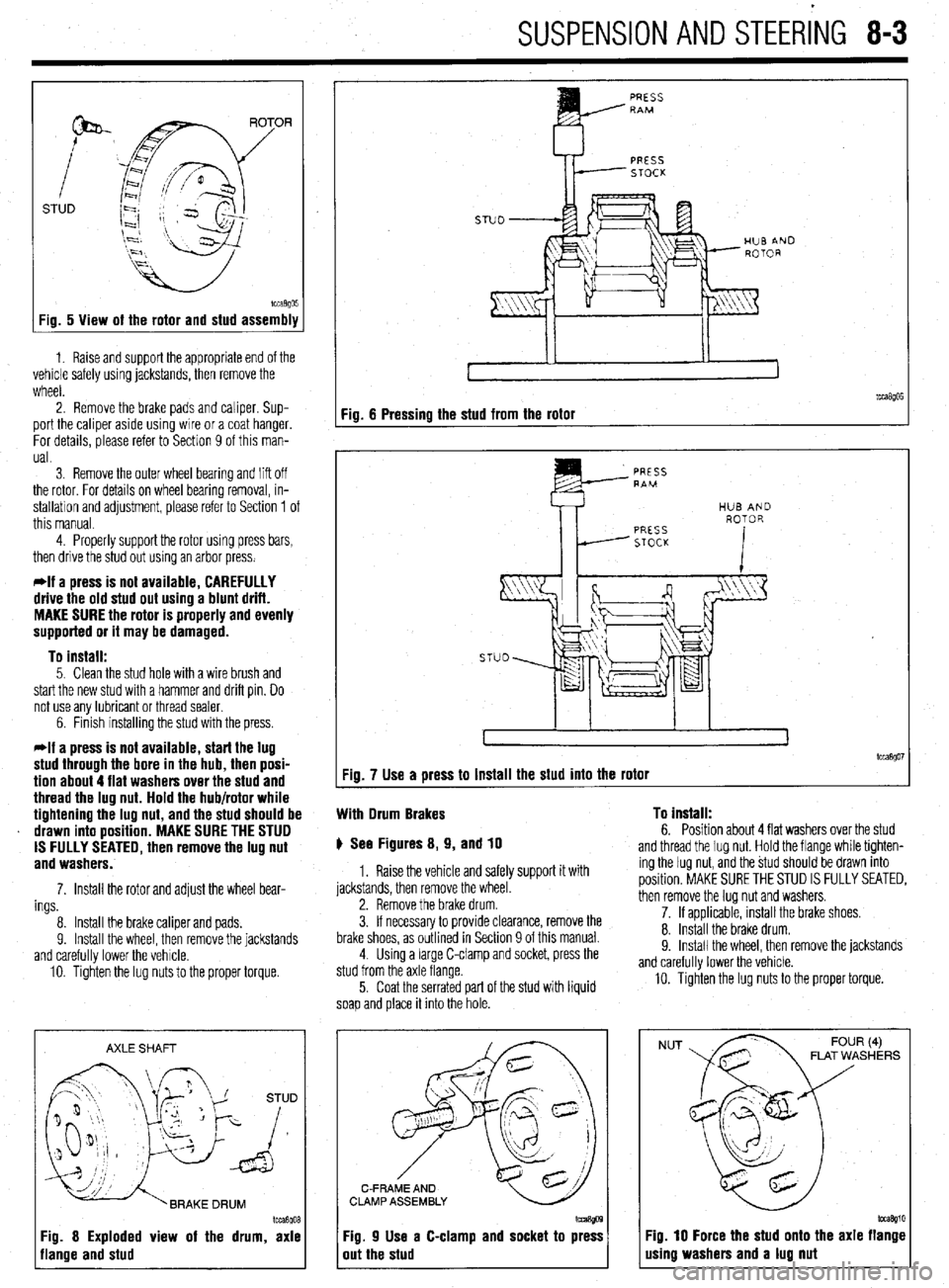
Fig. 5 View of the rotor and stud assembly
1. Raise and support the appropriate end of the
vehicle safely using jackstands, then remove the
wheel.
2. Remove the brake pads and caliper. Sup-
port the caliper aside using wire or a coat hanger.
For details, please refer to Section 9 of this man-
ual.
3 Remove the outer wheel bearing
and liff off
the rotor. For details on wheel bearing removal, in-
stallation and adjustment, please refer to Section 1 of
this manual.
4. Properly support the rotor using press bars,
then drive the stud out using an arbor press.
*If a press is not available, CAREFULLY
drive the old stud out using a blunt drift.
MAKE SURE the rotor is properly and evenly
supported or it may be damaged.
To install:
5. Clean the stud hole with a wire brush and
start the new stud with a hammer and drift pin. Do
not use any lubricant or thread sealer.
6. Finish installing the stud with the press.
*If a press is not available, start the lug
stud through the bore in the hub, then posi-
tion about 4 flat washers over the stud and
thread the lug nut. Hold the hub/rotor while
tightening the lug nut, and the stud should be
drawn into position. MAKE SURE THE STUD
IS FULLY SEATED, then remove the lug nut
and washers.
7. Install the rotor and adjust the wheel bear-
ings
8. Install the brake caliper and pads.
9. Install the wheel, then remove the jackstands
and carefully lower the vehicle.
10. Tighten the lug nuts to the proper torque.
AXLE SHAFT
Im3goa
3g. 8 Exploded view of the drum, axle
lange and stud
PRESS RAM
PRESS
STOCK
Fig. 6 Pressing the stud from the rotor
tcca$Oi Fig. 7 Use a press to install the stud into the rotor
With Drum Brakes To install:
6. Position about 4 flat washers over the stud p See Figures 8, 9, and 10
1. Raise the vehicle and safely support it with
jackstands, then remove the wheel.
2. Remove the brake drum.
3. If necessary to provide clearance, remove the
brake shoes, as outlined in Section 9 of this manual.
4. Using a large C-clamp and socket, press the
stud from the axle flange.
5. Coat the serrated part of the stud with liquid
soap and place it into the hole. and thread the lug nut. Hold the flange while tighten-
ing the lug nut, and the stud should be drawn into
position. MAKE SURE THE STUD IS FULLY SEATED,
then remove the lug nut and washers.
7. If applicable, install the brake shoes.
8. Install the brake drum.
9. Install the wheel. then remove the iackstands
and carefully lower the vehicle.
10. Tighten the lug nuts to the proper torque.
C-FRAME AND
CLAMP ASSEMBLY
Fig. 9 Use a C-clamp and socket to press
out the stud
NUT FLAT WASHERS
Fig. 10 Force the stud onto the axle flange
using washers and a lug nut
Page 356 of 408
‘I
9-20 ,BRAKES
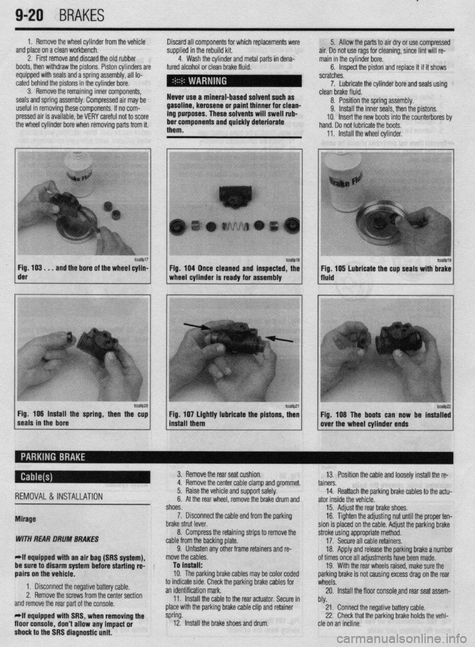
1. Remove the wheel cylinder from the vehicle
and place on a clean workbench.
2. First remove and discard the old rubber
boots, then withdraw the pistons. Piston cylinders are
equipped with seals and a spring assembly, all lo-
cated behind the pistons in the cylinder bore.
3. Remove the remaining inner components,
seals and spring assembly. Compressed air may be
useful in removing these components. If no com-
pressed air is available, be VERY careful not to score
the wheel cylinder bore when removing parts from it. Discard all components for which replacements were
supplied in the rebuild kit.
4. Wash the cylinder and metal parts in dena-
tured alcohol or clean brake fluid.
Never use a mineral-based solvent such as
gasoline, kerosene or paint thinner for clean-
ing purposes. These solvents will swell rub-
ber components and quickly deteriorate
them. 5. Allow the parts to air dry or use compressed
air. Do not use rags for cleaning, since lint will re-
main in the cylinder bore.
6. Inspect the piston and replace it if it shows
scratches.
7. Lubricate the cylinder bore and seals using
- clean brake fluid.
8. Position the spring assembly.
9. Install the inner seals, then the pistons.
IO. Insert the new boots into the counterbores bv
hand. Do not lubricate the boots,
11, Install the wheel cylinder,
m9017 Fig. 103. . .
and the bore of the wheel cylin- der
-9P20 Fig. 106 Install the spring, then the cup
seals in the bore 1 Fig. 104 Once cleaned and inspected, the
1 wheel cylinder Is ready for assembly
1 install them Fig 107 Lightly lubricate the pistons z
’ Fig. 108 The boots can now be instaT:
over the wheel cylinder ends
REMOVAL& INSTALLATION
Mirage
WITH REAR DRUM BRAKES
-If equipped witti an air bag (SRS system), 3. Remove the rear seat cushion.
13. Position the cable and loosely install the re-
4. Remove the center cable clamp and grommet.
tainers.
5. Raise the vehicle and support safely.
14. Reattach the parking brake cables to the actu-
6. At the rear wheel, remove the brake drum and
ator inside the vehicle.
shoes.
15. Adjust the rear brake shoes.
7. Disconnect the cable end from the parking
16. Tighten the adjusting nut until the proper ten-
brake strut lever.
sion is placed on the cable. Adjust the parking brake
8. Compress the retaining strips to remove the
stroke using appropriate method.
cable from the backing plate.
17. Secure all cable retainers,
9. Unfasten any other frame retainers and re-
18. Apply and release the parking brake a number
move the cables.
of times once all adjustments have been made.
be sure to disarm system
befok starting rd-
aairs on the vehicle. To install:
10. The parkinq brake cables mav be color coded 19. With the rear wheels raised, make sure the
oarkino brake is not causina excess draa on the rear
1. Disconnect the negative battery cable.
2. Remove the screws from the center section
and remove the rear part of the console.
*If equipped with SRS, when removing the
floor console,
don’t allow any impact or
shock to the SRS diagnostic unit. to indicate stde. Check the parking brake cables for
wheels: .A
an identification mark.
20. Install the floor consoleand rear seat assem-
11. Install the cable to the rear actuator. Secure in
bly.
place with the parking brake cable clip and retainer
21. Connect the negative battery cable.
spring.
22. Check that the parking brake holds the vehi-
12. Install the brake shoes and drum.
cle on an incline.
Page 357 of 408
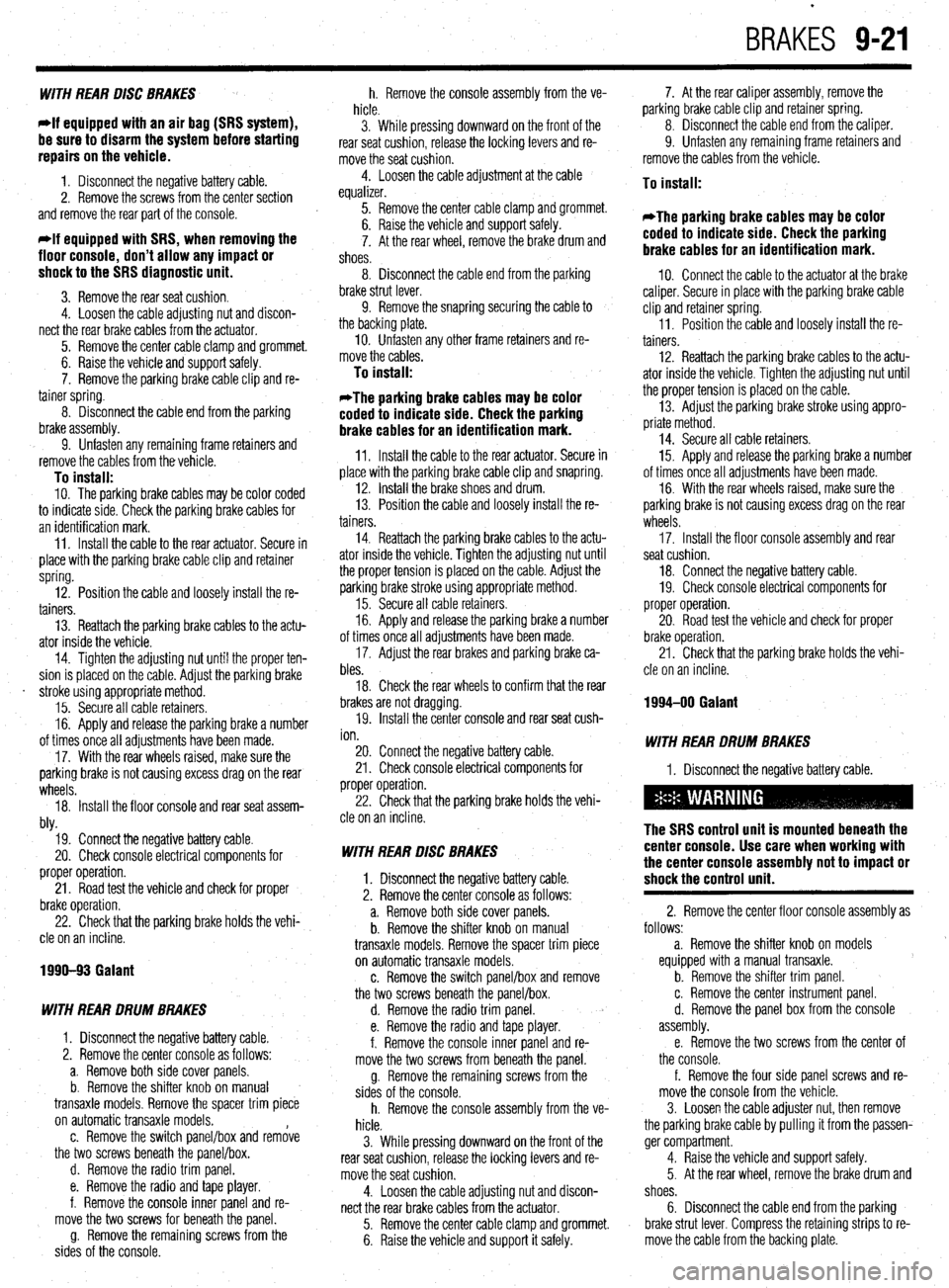
BRAKES 9-21
WITH REAR DISC BRAKES
*If equipped with an air bag (SRS system),
be sure to disarm the system before starting
repairs on the vehicle.
1. Disconnect the negative battery cable.
2. Remove the screws from the center section
and remove the rear part of the console.
*If equipped with SRS, when removing the
floor console, don’t allow any impact or
shock to the SRS diagnostic unit.
3. Remove the rear seat cushion.
4. Loosen the cable adjusting nut and discon-
nect the rear brake cables from the actuator.
5. Remove the center cable clamp and grommet.
6. Raise the vehicle and support safely.
7. Remove the parking brake cable clip and re-
tainer spring.
8. Disconnect the cable end from the parking
brake assembly.
9. Unfasten any remaining frame retainers and
remove the cables from the vehicle.
To install: IO. The parking brake cables may be color coded
to indicate side. Check the parking brake cables for
an identification mark.
11. Install the cable to the rear actuator. Secure in
place with the parking brake cable clip and retainer
spring.
12. Position the cable and loosely install the re-
tainers.
13. Reattach the parking brake cables to the actu-
ator inside the vehicle.
14. Tighten the adjusting nut until the proper ten-
sion is placed on the cable. Adjust the parking brake
. stroke using appropriate method.
15. Secure all cable retainers.
16. Apply and release the parking brake a number
of times once all adjustments have been made.
17. With the rear wheels raised, make sure the
parking brake is not causing excess drag on the rear
wheels.
18. Install the floor console and rear seat assem-
bly.
19. Connect the negative battery cable.
20. Check console electrical components for
proper operation.
21. Road test the vehicle and check for proper
brake operation.
22. Check that the parking brake holds the vehi-
cle on an incline.
1990-93 Galant
WITH REAR DRUM BRAKES
1. Disconnect the negative battery cable.
2. Remove the center console as follows:
a. Remove both side cover panels.
b. Remove the shifter knob on manual
transaxle models. Remove the spacer trim piece
on automatic transaxle models.
c. Remove the switch panel/box and remove
the two screws beneath the panel/box.
d. Remove the radio trim panel.
e. Remove the radio and tape player.
f. Remove the console inner panel and re-
move the two screws for beneath the panel.
g. Remove the remaining screws from the
sides of the console. h. Remove the console assembly from the ve-
hicle.
3. While pressing downward on the front of the
rear seat cushion, release the locking levers and re-
move the seat cushion.
4. Loosen the cable adjustment at the cable
equalizer.
5. Remove the center cable clamp and grommet.
6. Raise the vehicle and support safely.
7. At the rear wheel, remove the brake drum and
shoes.
8. Disconnect the cable end from the parking
brake strut lever.
9. Remove the snapring securing the cable to
the backing plate.
IO. Unfasten any other frame retainers and re-
move the cables.
To install:
*The parking brake cables may be color
coded to indicate side. Check the parking
brake cables for an identification mark.
11. Install the cable to the rear actuator. Secure in
place with the parking brake cable clip and snapring.
12. Install the brake shoes and drum.
13. Position the cable and loosely install the re-
tainers
14. Reattach the parking brake cables to the actu-
ator inside the vehicle. Tighten the adjusting nut until
the proper tension is placed on the cable. Adjust the
parking brake stroke using appropriate method.
15. Secure all cable retainers.
16. Apply and release the parking brake a number
of times once all adjustments have been made.
17. Adjust the rear brakes and parking brake ca-
bles.
18. Check the rear wheels to confirm that the rear
brakes are not dragging.
19. Install the center console and rear seat cush-
ion.
20. Connect the negative battery cable.
21. Check console electrical components for
proper operation.
22. Check that the parking brake holds the vehi-
cle on an incline.
WITH REAR DISC BRAKES
1. Disconnect the negative battery cable.
2. Remove the center console as follows:
a. Remove both side cover panels.
b. Remove the shifter knob on manual
transaxle models. Remove the spacer trim piece
on automatic transaxle models.
c. Remove the switch panel/box and remove
the two screws beneath the panel/box.
d. Remove the radio trim panel.
e. Remove the radio and tape player.
f. Remove the console inner panel and re-
move the two screws from beneath the panel.
g. Remove the remaining screws from the
sides of the console.
h. Remove the console assembly from the ve-
hicle.
3. While pressing downward on the front of the
rear seat cushion, release the locking levers and re-
move the seat cushion.
4. Loosen the cable adjusting nut and discon-
nect the rear brake cables from the actuator.
5. Remove the center cable clamp and grommet.
6. Raise the vehicle and support it safely. 7. At the rear caliper assembly, remove the
parking brake cable clip and retainer spring.
8. Disconnect the cable end from the caliper.
9. Unfasten any remaining frame retainers and
remove the cables from the vehicle.
To install:
*The parking brake cables may be color
coded to indicate side. Check the parking
brake cables for an identification mark.
IO. Connect the cable to the actuator at the brake
caliper. Secure in place with the parking brake cable
clip and retainer spring.
11. Position the cable and loosely install the re-
tainers.
12. Reattach the parking brake cables to the actu-
ator inside the vehicle. Tighten the adjusting nut until
the proper tension is placed on the cable.
13. Adjust the parking brake stroke using appro-
priate method.
14. Secure all cable retainers.
15. Apply and release the parking brake a number
of times once all adjustments have been made.
16. With the rear wheels raised, make sure the
parking brake is not causing excess drag on the rear
wheels.
17. Install the floor console assembly and rear
seat cushion.
18. Connect the negative battery cable.
19. Check console electrical components for
proper operation.
20. Road test the vehicle and check for proper
brake operation.
21. Check that the parking brake holds the vehi-
cle on an incline.
1994-00 Galant
WITH REAR DRUM BRAKES
1. Disconnect the negative battery cable.
The SRS control unit is mounted beneath the
center console. Use care when working with
the center console assembly not to impact or
shock the control unit.
2. Remove the center floor console assembly as
follows:
a. Remove the shifter knob on models
equipped with a manual transaxle.
b. Remove the shifter trim panel.
c. Remove the center instrument panel.
d. Remove the panel box from the console
assembly.
e. Remove the two screws from the center of
the console.
f. Remove the four side panel screws and re-
move the console from the vehicle.
3. Loosen the cable adjuster nut, then remove
the parking brake cable by pulling it from the passen-
ger compartment.
4. Raise the vehicle and support safely.
5. At the rear wheel, remove the brake drum and
shoes.
6. Disconnect the cable end from the parking
brake strut lever. Compress the retaining strips to re-
move the cable from the backing plate.
Page 406 of 408
l
II-24 MASTER INDEX
ADJUSTMENT 8-25
REMOVAL &INSTALLATION 8-25
HYDRAULIC CONTROL UNIT 9-25
REMOVAL & INSTALLATION 9-25
IDLE AIR CONTROLMOTOR 4-9
OPERATION 4-9
REMOVAL&INSTALLATION 4-9
TESTING 4-9
IDLESPEED 1-28
PREVENTIVEMAINTENANCE 1-28
SYSTEM INSPECTION 1-29
SYSTEMSERVlCE&REPAlR 1-28
IGNITION LOCK CYLINDER 8-29
REMOVAL & INSTALLATION 8-29
IGNITION SWITCH 8-30
REMOVAL & INSTALLATION 8-30
IGNITION COIL(s) 2-5
REMOVAL&INSTALLATION 2-6
TESTING . 2-5
IGNITION COIL 2-3
REMOVAL&INSTALLATION 2-3
TESTING 2-3
IGNITION TIMING l-25
GENERALINFORAMTION l-25
INSPECTION&ADJUSTMENT l-26
INSIDE REAR VIEW MIRROR
IO-IO
REPLACEMENT IO-IO
INSPECTION 3-55
REPLACEMENT 3-56
INSTRUMENT CLUSTER 6-17
REMOVAL&INSTALLATION 6-I;
INSTRUMENTPANEL IO-6
REMOVAL &INSTALLATION IO-6
INSTRUMENTS AND SWITCHES 6-17
INTAKE MANIFOLD 3-7
REMOVAL &INSTALLATION 3-7
INTAKEAIRTEMPERATURESENSOR 4-10
OPERATION 4-10
REMOVAL&INSTALLATION 4-11
TESTING 4-11
INTERIOR 1 O-6
JACKING I-46
. JACKING PRECAUTIONS 1-47
JUMP STARTING A DEAD BATTERY 1-44
JUMPSTARTING PRECAUTIONS l-45
JUMPSTARTING PROCEDURE l-45
KNUCKLE,HUB, AND BEARING 8-13
REMOVAL &INSTALLATION 8-13
LIGHTING 6-19
LOWER BALLJOINT 8-10
INSPECTION 8-10
REMOVAL & INSTALLATION 8-10
LOWER CONTROLARM 8-10
REMOVAL&INSTALLATION 8-10
LOWER CONTROL ARMS 8-23
REMOVAL & INSTALLATION 8-23
MACPHERSONSTRUTAND COILSPRING
8-7
OVERHAUL 8-7
REMOVAL & INSTALLATION 8-7
MAINTENANCEORREPAIR? l-2
MANIFOLDABSOLUTEPRESSURESENSOR
4-12
OPERATION 4-12
REMOVAL&INSTALLATION 4-13
TESTING 4-12
MANUAL RACK AND PINION STEERING GEAR
8-31
REMOVAL & INSTALLATION 8-31
MANUALTRANSAXLEASSEMBLY 7-2
REMOVAL & INSTALLATION. 7-2
MANUAL TRANSAXLE 7-2 MANUALTRANSAXLE l-35
DRAIN &REFILL l-36
FLUID RECOMMENDATIONS l-35
LEVEL CHECK l-35
MASSAIRFLOWSENSOR 4-11
OPERATION 4-11
REMOVAL&INSTALLATION 4-11
TESTING 4-11
MASTER CYLINDER 9-3
BRAKE PEDALADJUSTMENTS 9-4
REMOVAL & INSTALLATION 9-3
MULTI-POINT FUEL INJECTION SYSTEM (MPI) 5-3
DBD-1 TROUBLE CODES 4-26
OBD-II TROUBLE CODES 4-27
OIL PAN 3-30
REMOVAL & INSTALLATION 3-30
OIL PUMP 3-33
REMOVAL & INSTALLATION 3-33
OIL PRESSURESENDING UNIT 2-12@T
REMOVAL&INSTALLATION 2-1.2
TESTING 2-12
OUTSIDE MIRRORS IO-3
REMOVAL&INSTALLATION IO-3
OXYGENSENSOR 4-8
OPERATION 4-8
REMOVAL&INSTALLATION 4-8
TESTING 4-8
PARK/NEUTRAL POSITIONSWITCH 7-10
ADJUSTMENT 7-10
REMOVAL & INSTALLATION 7-10
PARKING BRAKE 9-20
PCVVALVE l-15
REMOVAL&INSTALLATION I-15
PINION SEAL 7-16
REMOVAL &INSTALLATION 7-16
POWER BRAKEBOOSTER 9-5
REMOVAL &INSTALLATION 9-5
POWER RACK AND PINION STEERING GEAR 8-32
REMOVAL &INSTALLATION 8-32
POWERSEATMOTOR IO-11
REMOVAL & INSTALLATION IO-11
POWER STEERING PUMP 8-34
REMOVAL & INSTALLATION 8-34
SYSTEM BLEEDING 8-36
POWER TRANSlSTOR(IGNITION MODULE) 2-7
REMOVAL&INSTALLATION 2-7
POWERSTEERING PUMP l-42
FLUID RECOMMENDATIONS l-42
LEVELCHECK l-42
POWER TRANSlSTOR(Ignition Module) 2-4
REMOVAL&INSTALLATION 2-4
PRESSURERELIEFVALVE 5-9
REMOVAL&INSTALLATION 5-9
PROPORTIONING VALVE 9-6
REMOVAL & INSTALLATION 9-6 *
RADIATOR 3-18
REMOVAL &INSTALLATION 3-18
RADIO RECEIVER/AMPLIFIER/TAPE PLAYER/CD PLAYER 6-14
READING CODES 4-26
WITHASCANTOOL 4-26
WITHOUTASCANTOOL 4-27
READING CODES 4-27
WITHASCANTOOL 4-27
WITHOUTASCANTOOL 4-27
REAR AXLE DIFFERENTIAL 7-15
REAR HALFSHAFTAND SEAL 7-15
REMOVAL&INSTALLATION 7-15
REAR MAIN SEAL 3-54
REMOVAL & INSTALLATION 3-54
Page 407 of 408
MASTER INDEX 11-25 -
REAROUTPUTSHAFTSEAL 7-14
TESTING 6-5
REMOVAL & INSTALLATION 7-14
' THERMOSTAT 3-7
REAR SUSPENSION 8-18 REMOVAL & INSTALLATION 3-7
REAR WINDOW WIPER SWITCH 6-19 THROTTLE BODY 5-3
REMOVAL&INSTALLATION 6-19 REMOVAL & INSTALLATION 5-3
REARDRlVEAXLE(AWDGALANTONLY) l-38
THROTTLEPOSITIONSENSOR 4-13
DRAIN &REFILL 1-38
OPERATION 4-13
FLUIDRECOMMENDATIONS 1-38 , REMOVAL&INSTALLATION 4-13
LEVELCHECK l-38
TESTING 4-13
REGULATOR 2-10 TIMING COVERAND BELT 3-36
REMOVAL&INSTALLATION 2-10
INSPECTION 3-48
RELIEVING FUELSYSTEM PRESSURE 5-3 REMOVAL & INSTALLATION 3-36
ROCKERARM(VALVE)COVER 3-1
TIMING BELTS l-20
REMOVAL & INSTALLATION 3-1
INSPECTION I-20
ROCKER ARM/SHAFTS 3-4
TIRESANDWHEELS I-30
REMOVAL & INSTALLATION 3-4
CAREOFSPECIALWHEELS l-32
ROUTINE MAINTENANCE AND TUNE-UP 1-14 INFLATION & INSPECTION I-31
SEATS IO-IO
TIRE DESIGN I-31
REMOVAL&INSTALLATION IO-IO TIRE ROTATION I-30
SENDING UNITS 2-11
TIRESTORAGE I-31
SERIAL NUMBER IDENTIFICATION l-10
TONE (EXCITER) RING 9-29
SERVICING YOUR VEHICLE SAFELY I-4
REMOVAL & INSTALLATION 9-29
SHOCKABSORBERAND COILSPRING 8-8
TOOLS AND EQUIPMENT 1-2
OVERHAUL 8-9
TORQUE 1-7
REMOVAL&INSTALLATION 8-8 TORQUEANGLEMETERS l-9
SIGNAL AND MARKER LIGHTS 6-21
TORQUEWRENCHES l-7
REMOVAL & INSTALLATION 6-21
TOWING THE VEHICLE 1-44
SPARKPLUG WIRES 1-24
TRAINING ARM 8-24
REMOVAL&INSTALLATION 1-24
REMOVAL & INSTALLATION 8-24
TESTING 1-24
TRANSAXLEIDENTIFICATION I-10
SPARKPLUGS l-22
TRANSFER CASE ASSEMBLY 7-14
INSPECTION &GAPPING l-23
REMOVAL & INSTALLATION 7-14
REMOVAL&INSTALLATION 1-22
TRANSFER CASE 7-14
SPARKPLUGHEATRANGE 1-22
TRANSFERCASE(AWD GALANT ONLY) 1-38
SPEAKERS 6-14
DRAIN &REFILL 1-38
REMOVAL & INSTALLATION 6-14
FLUIDRECOMMENDATIONS 1-38
SPECIALTOOLS 1-4
LEVELCHECK 1-38
SPEED SENSORS 9-28
TRANSFERCASE(AWDGALANTONLY) I-10
REMOVAL & INSTALLATION 9-28
TROUBLESHOOTING ELECTRICALSYSTEMS 6-5
STANDARDANDMETRIC MEASUREMENTS l-9
OPEN CIRCUITS 6-5
STARTER 2-10
RESISTANCE 6-8
REMOVAL&INSTALLATION 2-11
SHORT CIRCUITS 6-6
TESTING 2-10
VOLTAGEDROP 6-6
STARTING SYSTEM 2-10
VOLTAGE 6-6
STEERING LINKAGE 8-30
TRUNK LID IO-3
REMOVAL &INSTALLATION 8-30
ALIGNMENT IO-3
STEERING WHEEL 8-27
REMOVAL & INSTALLATION IO-3
REMOVAL &INSTALLATION 8-27
TURBOCHARGER 3-17
STEERING 8-27
REMOVAL & INSTALLATION 3-17
STRUT AND COIL SPRING
8-21
UNDERSTANDING AND TROUBLESHOOTING ELECTRICAL
OVERHAUL 8-22
SYSTEMS 6-2
REMOVAL & INSTALLATION 8-21
UNDERSTANDINGTHEAUTOMATICTRANSAXLE 7-10
STUBAXLESHAFT,BEARlNG AND SEAL 7-15
REMOVAL & INSTALLATION 7-10
REMOVAL&INSTALLATION 7-15
UNDERSTANDINGTHECLUTCH 7-7
SWAY BAR 8-12
ADJUSTMENTS 7-8
REMOVAL 8, INSTALLATION 8-12
REMOVAL&INSTALLATION 7-7
SWAY BAR 8-25
UNDERSTANDINGTHE MANUALTRANSAXLE 7-2
REMOVAL&INSTALLATION 8-25
SHIFT LINKAGE 7-2
TAILGATE/HATCH HANDLE lo-19
UPPER BALLJOINT 8-9
REMOVAL &INSTALLATION lo-10
INSPECTION 8-9
TAILGATE IO-3
REMOVAL &INSTALLATION 8-9
ALIGNMENT IO-3 i'
UPPER CONTROLARM 8-10
REMOVAL & INSTALLATION IO-3
REMOVAL & INSTALLATION 8-10
TANKASSEMBLY 5-10
UPPER CONTROL ARMS 8-22
REMOVAL&INSTALLATION 5-10
REMOVAL & INSTALLATION 8-22
TEST EQUIPMENT 6-4
VACUUM DIAGRAMS 4-36
JUMPER WIRES 6-4
VALVE LASH 1-27
MULTIMETERS 6-5
ADJUSTMENT 1-27
TEST LIGHTS 6-4
VEHICLE IDENTIFICATION NUMBER I-10