oil MITSUBISHI DIAMANTE 1900 Repair Manual
[x] Cancel search | Manufacturer: MITSUBISHI, Model Year: 1900, Model line: DIAMANTE, Model: MITSUBISHI DIAMANTE 1900Pages: 408, PDF Size: 71.03 MB
Page 1 of 408
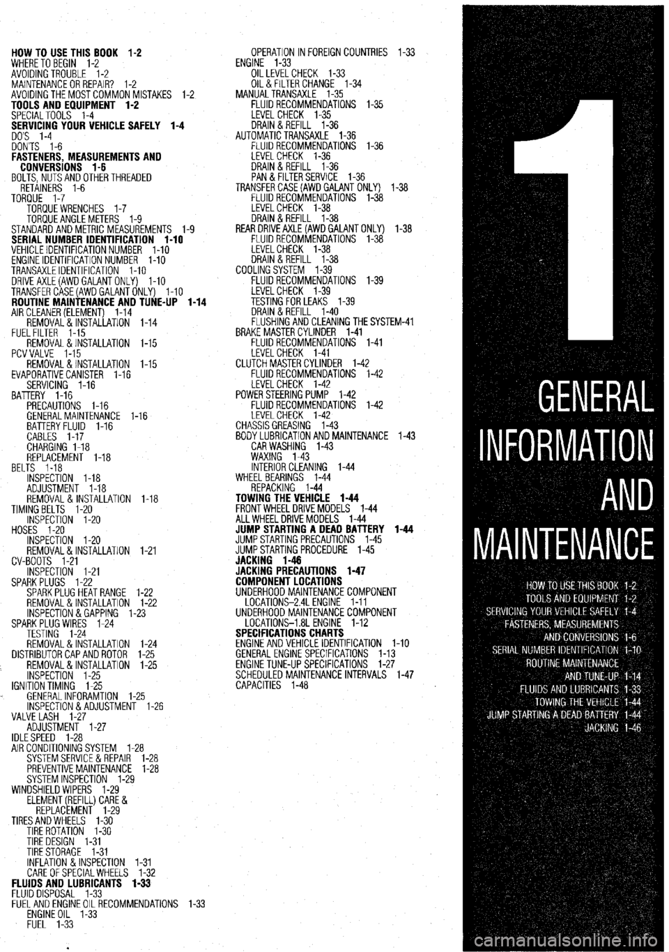
HOW TO USE THIS BOOK 1-2
WHERE TOBEGIN l-2
AVOIDINGTROUBLE 1-2
MAINTENANCEORREPAIR? 1-2
AVOIDINGTHEMOSTCOMMONMISTAKES l-2
TOOLS AND EQUIPMENT 1-2
SPECIALTOOLS l-4
YOUR VEHICLE SAFELY 1-4
DON'TS l-6
FASTENERS, MEASUREMENTS AND
CONVERSIONS l-6
BOLTS,NUTSANDOTHERTHREADED
RETAINERS 1-6
TORQUE l-7
TORQUEWRENCHES l-7
TORQUEANGLEMETERS 1-9
STANDARDANDMETRIC MEASUREMENTS l-9
SERIAL NUMBER IDENTIFICATION l-10
VEHICLE IDENTIFICATION NUMBER l-10
ENGINE IDENTIFICATION NUMBER I-10
TRANSAXLEIDENTIFICATION I-10
DRlVEAXLE(AWDGALANTONLY) l-10
TRANSFERCASE(AWDGALANTONLY) l-10
ROUTINE MAINTENANCE AND TUNE-UP l-14
AIRCLEANER(ELEMENT) 1-14
REMOVAL&INSTALLATION 1-14
FUELFILTER 1-15
REMOVAL &INSTALLATION l-15
PCVVALVE l-15
REMOVAL&INSTALLATION l-15
EVAPORATIVECANISTER l-16
SERVICING 1-16
BATTERY 1-16
PRECAUTIONS I-16
GENERALMAINTENANCE 1-16
BEL BATTERYFLUID 1-16
CABLES I-17
CHARGING I-18
REPLACEMENT 1-18
TS 1-18
INSPECTiON l-18
ADJUSTMENT 1-18
REMOVAL&INSTALLATION 1-18
TIMINGBELTS l-20
INSPECTION l-20
HOSES I-20
INSPECTION l-20
REMOVAL&INSTALLATION
CV-BOOTS 1-21
INSPECTION l-21
SPARKPLUGS l-22
SPARKPLUGHEATRANGE
REMOVAL&INSTALLATION
INSPECTION &GAPPING 1.
SPARKPLUG WIRES 1-24
TESTING 1-24
REMOVAL&INSTALLATION
DISTRIBUTORCAPANDROTOR
REMOVAL&INSTALLATION
INSPECTION 1-25
IGNITIONTIMING 1-25
. GENERALINFORAMTION l-
lNSPECTlON&ADJUSTMENl
VALVE LASH l-27
ADJUSTMENT l-27
IDLESPEED 1-28 1-21
l-22
l-22
-23
1-24
l-25
l-25
.25
1-26
AIR CONDITIONING SYSTEM 1-28
SYSTEMSERVlCEiiREPAlR l-28
PREVENTIVEMAINTENANCE 1-28
SYSTEM INSPECTION l-29
WINDSHIELD WIPERS l-29
ELEMENT(REFILL)CARE&
REPLACEMENT l-29
TIRESANDWHEELS l-30
TIRE ROTATION I-30
TIRE DESIGN 1-31
TIRESTORAGE l-31
INFLATION &INSPECTION l-31
CARE OFSPECIALWHEELS l-32 OPERATION INFOREIGNCOUNTRIES l-33
ENGINE l-33
OILLEVELCHECK 1-33
OIL& FILTER CHANGE l-34
MANUALTRANSAXLE l-35
FLUIDRECOMMENDATIONS l-35
LEVELCHECK l-35
DRAIN&REFILL l-36
AUTOMATICTRANSAXLE l-36
FLUIDRECOMMENDATIONS l-36
LEVELCHECK 1-36
DRAIN&REFILL l-36
PAN & FILTERSERVICE 1-36
TRANSFERCASE(AWDGAlANT ONLY) l-38
FLUIDRECOMMENDATIONS l-38
LEVELCHECK l-38
DRAIN&REFILL l-38
REARDRlVEAXLE(AWDGALANTONLY) l-38
FLUIDRECOMMENDATIONS l-38
LEVELCHECK l-38
DRAIN&REFILL l-38
COOLINGSYSTEM l-39
FLUIDRECOMMENDATIONS l-39
iM-41
FLUIDS AND LUBRICANTS 1-33
FLUID DISPOSAL 1-33
FlJELANDENGlNEOILRECOMMENDATlONS
ENGINE OIL l-33
FUEL l-33
Page 3 of 408
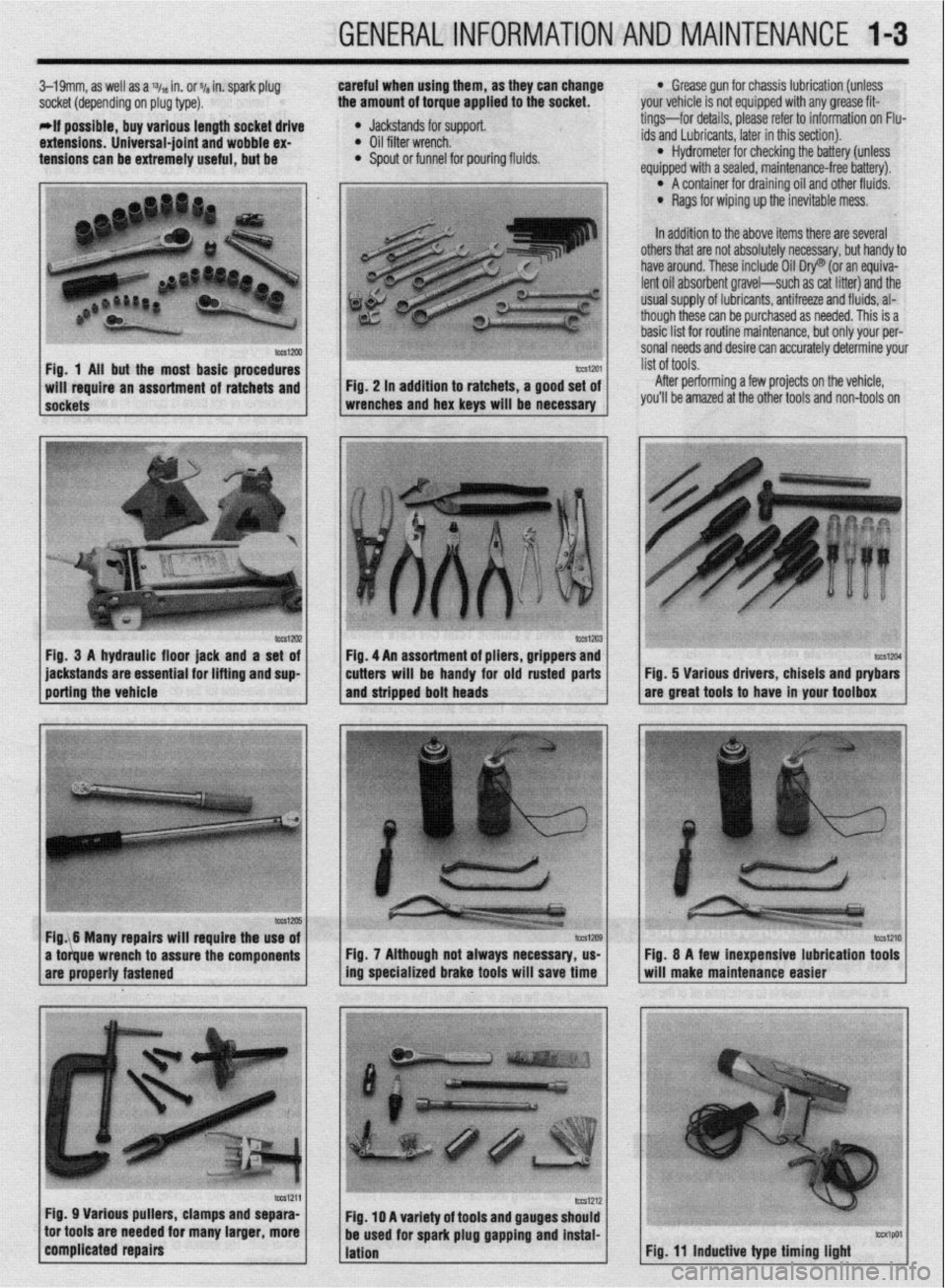
GENERALINFORMATIONAND MAINTENANCE l-3
3-19mm, as well as a % in. or ~/a in. spark plug careful when using them, as they can change
socket (depending on plug type). the amount of torque applied to the socket.
-if possible, buy various length socket drive
l Jackstands for support.
extensions. Universal-joint and wobble ex- l Oil filter wrench.
tensions can be extremely useful, but be l Spout or funnel for pouring fluids.
l Grease gun for chassis lubrication (unless
your vehicle is not equipped with any grease fit-
tings-for details, please refer to information on Flu-
ids and Lubricants, later in this section).
l Hydrometer for checking the battery (unless
equiooed with a sealed, maintenance-free batten/).
In addition to the above items there are several O’ A container for draining oil and other fluids.
l Rags for wiping up the inevitable mess.
pi 1 others that are not absolutely necessary, but handy to
have around. These include Oil Dry@ (or an equiva-
lent oil absorbent gravel-such as cat litter) and the
usual SUDDIV of lubricants. antifreeze and fluids. al-
though the.& can be purchased as needed. This is a
basic list for routine maintenance, but only your per-
sonal needs and desire can accurately determine your
Fig. 1 Ail but the most basic procedures
After performing a few projects on the vehicle,
you’ll be amazed at the other tools and non-tools on
lWSl2U2 Fig, 3 A hydraulic floor jack and a set of
jackstands are essential for lifting and sup
porting the vehicle tm1204 Fig. 5 Various drivers, chisels and ptybars
are great tools to have in your toolbox
Fig. 7 Although not always necessary, us-
ing specialized brake tools will save time
Fig. 11 inductive type timing light
Page 5 of 408
1-6 GENERALINFORMATIONAND MAINTENANCE
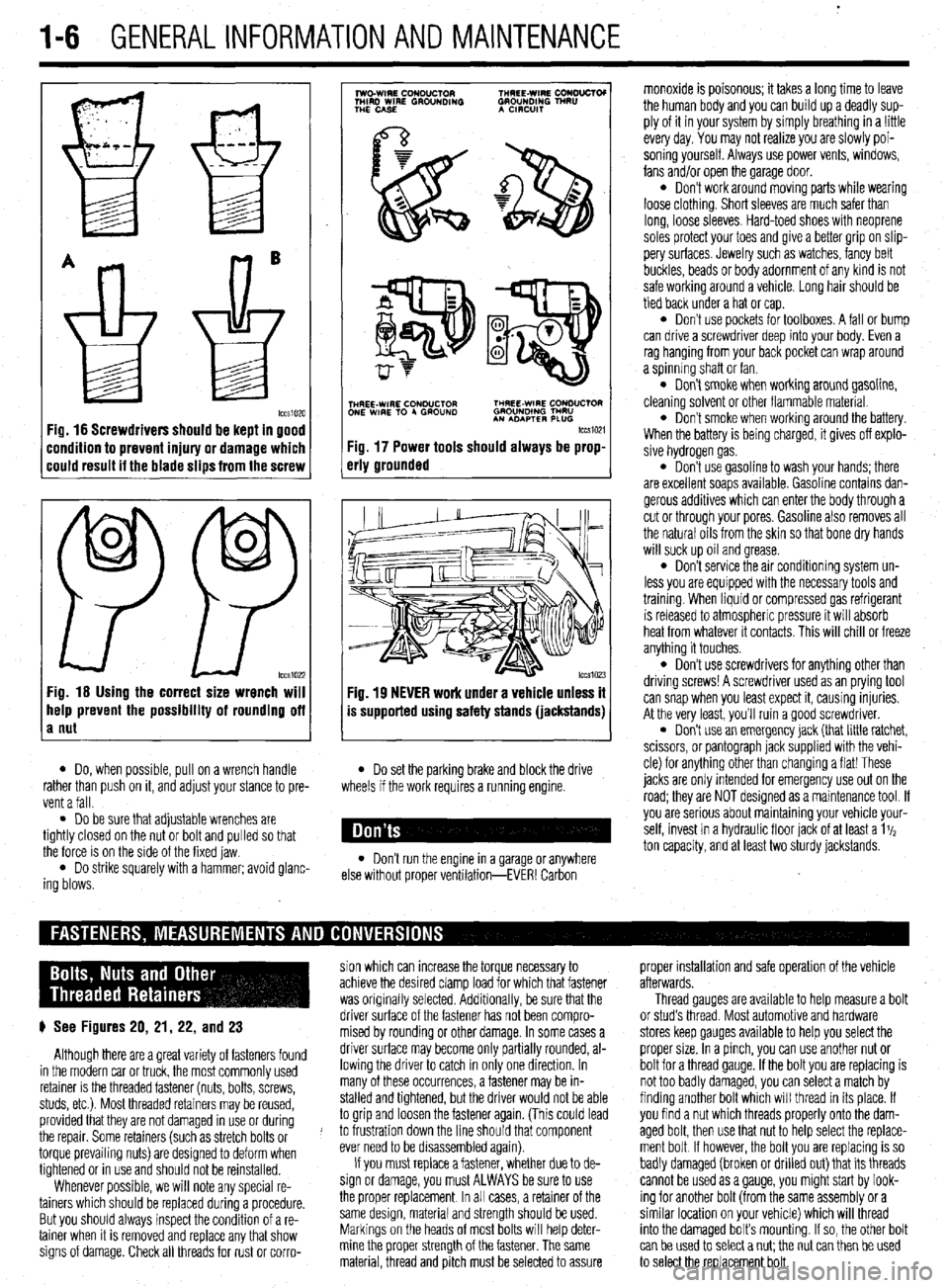
Fig. 16 Screwdrivers should be kept in good
:ondition to prevent injury or damage which
:ould result it the blade slips from the screw
0
0
PP tccs1022 Fig. 16 Using the correct size wrench will
help prevent the possibility of rounding off
a nut
7
lwo.WIRE CouDuClOR TMREE-WIRE CONO”CTOI
MIRD WIRE GROUNDING GROUNDING TNRU
THE CASE A CmxlIT
.
i$Y$$pQ
p-+
TNHREE-WIRE CONDUCTOR THREE-WIRE CONDUCTOR
ONE WIRE TO 4 GROUND GROUNOlNG TMRU
AN ADAPTER PLUG
tccm21
Fig. 17 Power tools should always be prop-
erly grounded
Fig. 19 NEVER work under a vehicle unless it
is supported using safety stands (jackstands)
l Do, when possible, pull on a wrench handle l Do set the parking brake and block the drive
rather than push on it, and adjust your stance to pre-
vent a fall. wheels if the work requires a running engine.
l Do be sure that adjustable wrenches are
tightly closed on the nut or bolt and pulled so that
the force is on the side of the fixed jaw.
l Do strike squarely with a hammer; avoid glanc-
ing blows. l Don’t run the engine in a garage or anywhere
else without proper ventilation-EVER! Carbon monoxide is poisonous; it takes a long time to leave
the human body and you can build up a deadly sup-
ply of it in your system by simply breathing in a !ittle
every day. You may not realize you are slowly poi-
soning yourself. Always use power vents, windows,
fans and/or open the garage door.
l Don’t work around moving parts while wearing
loose clothing. Short sleeves are much safer than
long, loose sleeves. Hard-toed shoes with neoprene
soles protect your toes and give a better grip on slip-
pery surfaces. Jewelry such as watches, fancy belt
buckles, beads or body adornment of any kind is not
safe working around a vehicle. Long hair should be
tied back under a hat or cap.
l Don’t use pockets for toolboxes. A fall or bump
can drive a screwdriver deep into your body. Even a
rag hanging from your back pocket can wrap around
a spinning shaft or fan.
l Don’t smoke when working around gasoline,
cleaning solvent or other flammable material.
l Don’t smoke when workrng around the battery.
When the battery is being charged, it gives off explo-
sive hydrogen gas.
l Don’t use gasoline to wash your hands; there
are excellent soaps available. Gasoline contains dan-
gerous additives which can enter the body through a
cut or through your pores. Gasoline also removes all
the natural oils from the skin so that bone dry hands
will suck up oil and grease.
l Don’t service the air conditioning system un-
less you are equipped with the necessary tools and
trainmg. When liquid or compressed gas refrigerant
is released to atmospheric pressure it will absorb
heat from whatever it contacts. This will chill or freeze
anything it touches.
l Don’t use screwdrivers for anything other than
driving screws! A screwdriver used as an prying tool
can snap when you least expect it, causing injuries.
At the very least, you’ll ruin a good screwdriver.
. Don’t use an emergency jack (that little ratchet,
scissors, or pantograph jack supplied with the vehi-
cle) for anything other than changing a flat! These
jacks are only Intended for emergency use out on the
road; they are NOT designed as a maintenance tool. If
you are serious about mamtaining your vehicle your-
self, invest in a hydraulic floor jack of at least a 1%
ton capacity, and at least two sturdy jackstands.
sion which can increase the torque necessary to proper installation and safe operation of the vehicle
achieve the desired clamp load for which that fastener afterwards.
was originally selected. Additionally, be sure that the Thread gauges are available to help measure a bolt
p See Figures 20, 21, 22, and 23 driver surface of the fastener has not been compro- or stud’s thread. Most automotive and hardware
mised by rounding or other damage. In some cases a stores keep gauges available to help you select the
Although there are a great variety of fasteners found driver surface may become only partially rounded, al- proper size. In a pinch, you can use another nut or
in the modern car or truck, the most commonly used lowing the driver to catch in only one direction. In bolt for a thread gauge. If the bolt you are replacing is
retainer is the threaded fastener (nuts, bolts, screws, many of these occurrences, a fastener may be in- not too badly damaged, you can select a match by
studs, etc.). Most threaded retainers may be reused, stalled and tightened, but the driver would not be able finding another bolt which will thread in its place. If
provided that they are not damaged in use or during to grip and loosen the fastener again. (This could lead you find a nut which threads properly onto the dam-
the repair. Some retainers (such as stretch bolts or J to frustration down the line should that component aged bolt, then use that nut to help select the replace-
torque prevailing nuts) are designed to deform when ever need to be disassembled again). ment bolt If however, the bolt you are replacing is so
tightened or in use and should not be reinstalled. If you must replace a fastener, whether due to de- badly damaged (broken or drilled out) that its threads
Whenever possible, we will note any special re- sign or damage, you must ALWAYS be sure to use cannot be used as a gauge, you might start by look-
tainers which should be replaced during a procedure. the proper replacement In all cases, a retainer of the ing for another bolt (from the same assembly or a
But you should always inspect the condition of a re- same design, material and strength should be used. similar location on your vehicle) which will thread
tainer when It is removed and replace any that show Markings on the heads of most bolts will help deter- into the damaged bolt’s mounting. If so, the other bolt
signs of damage. Check all threads for rust or corro- mine the proper strength of the fastener. The same
can be used to select a nut; the nut can then be used
material, thread and pitch must be selected to assure
to select the replacement bolt.
Page 10 of 408
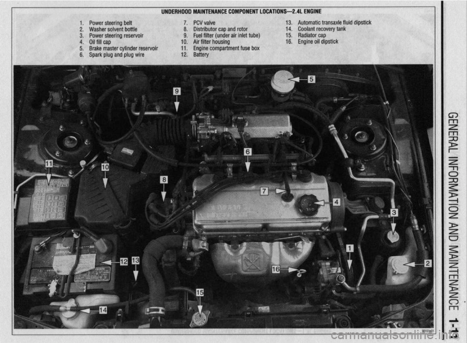
UNDERHDDD MAINTENANCE COMPONENT LOCATIONS-2AL ENGINE
II
1. Power steering belt 7. PCV valve
2. Washer solvent bottle 8. Distributor cap and rotor
3. Power steering reservoir 9. Fuel filter (under air inlet tube)
4. Oil fill cap 10. Air filter housing
5. Brake master cylinder reservoir 11. Engine compartment fuse box
6. Spark plug and plug wire 12. Battery 13. Automatic transaxle fluid dipstick
14. Coolant recovery tank
15. Radiator cap
16. Engine oil dipstick
Page 11 of 408
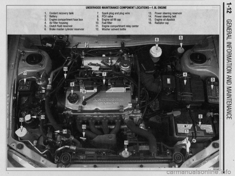
UNDERHOOD MAINTENANCE COMPONENT LOCATIONS-l .8L ENGINE
1. Coolant recovery tank
2. Battery
3. Engine compartment fuse box
4. Air filter housing
5. Clutch fluid reservoir
6. Brake master cylinder reservoir 7. Spark plug and plug wire
8. PCV valve
9. Engine oil fill cap
10. Fuel filter
11. Engine compartment relay center
12. Washer solvent bottle 13. Power steering reservoir
14. Power steering belt
15. Engine oil dipstick
16. Radiator cap
Page 12 of 408
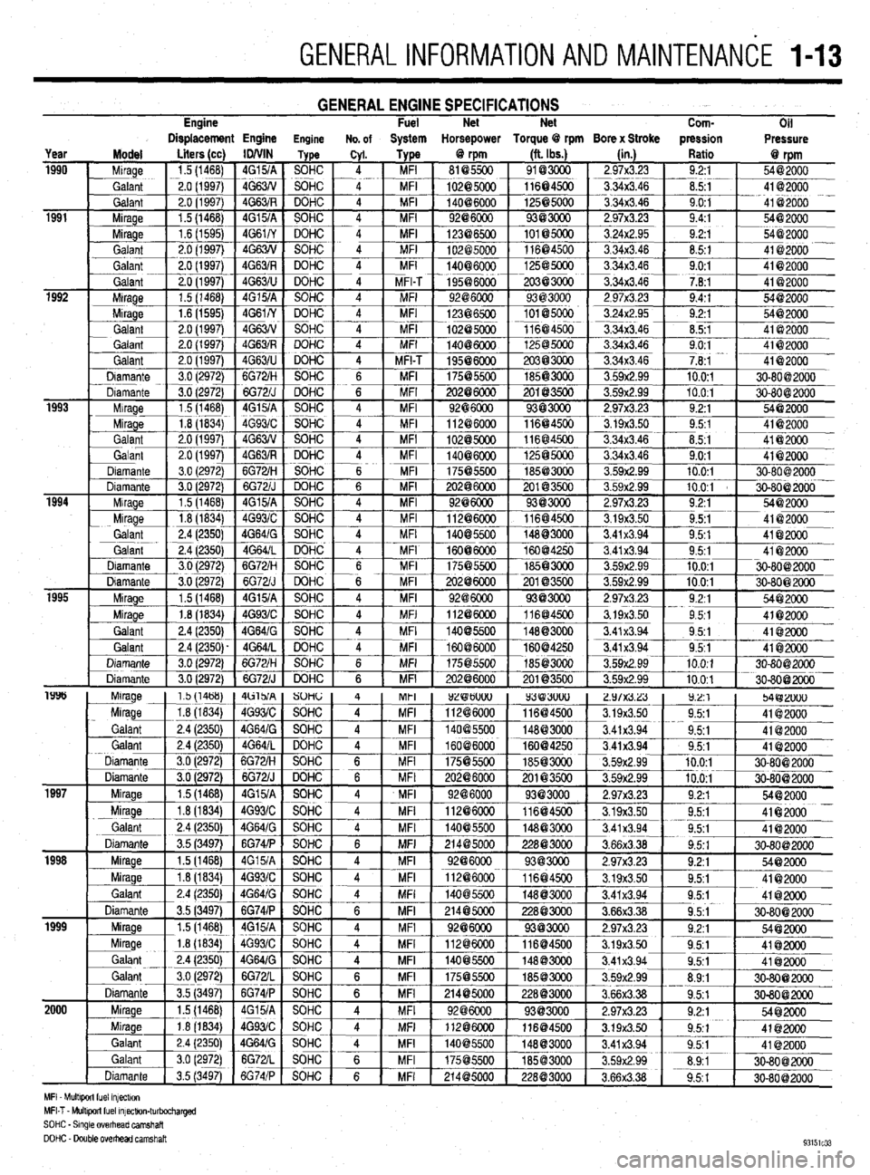
GENERALINFORMATIONAND MAlNTENANdE 1-13
Engine GENERAL ENGINE SPECIFICATIONS Fuel Net Net
Com-
Oil
Displacement Engine Engine No. of System Horsepower Torque @ rpm Bore x Stroke pression
Pressure
MFI Mult+wt fuel mfectw,
MFI-T - Multlporl fuel mfectlon-turbocharged
SOHC - Smgle overhead camshaft
DOHC - Double OvedEad camshaft
Page 13 of 408
l
l-14 GENERALINFORMATIONAND MAINTENANCE
Proper maintenance and tune-up is the key to long
and trouble-free vehicle life, and the work can yield
its own rewards. Studies have shown that a properly
tuned and maintained vehicle can achieve better gas
mileage than an out-of-tune vehicle. As a conscien-
tious owner and driver, set aside a Saturday morning,
say once a month, to check or replace items which
could cause major problems later. Keep your own
personal log to jot down which services you per-
formed, how much the parts cost you, the date, and
the exact odometer reading at the time. Keep all re-
selfer, these receipts are the only proof you have that ceipts for such items as engine oil and filters, so that
they may be referred tp in case of related problems or
to determine operating expenses. As a do-it-your- the required maintenance was performed. In the event
of a warranty problem, these receipts will be invalu-
able.
The literature provided with your vehicle when it
was originally delivered includes the factory recom-
mended maintenance schedule. If you no longer have
this literature, replacement copies are usually avail-
able from the dealer. A maintenance schedule is pro-
vided later in this section, in case you do not have
the factory literature. *
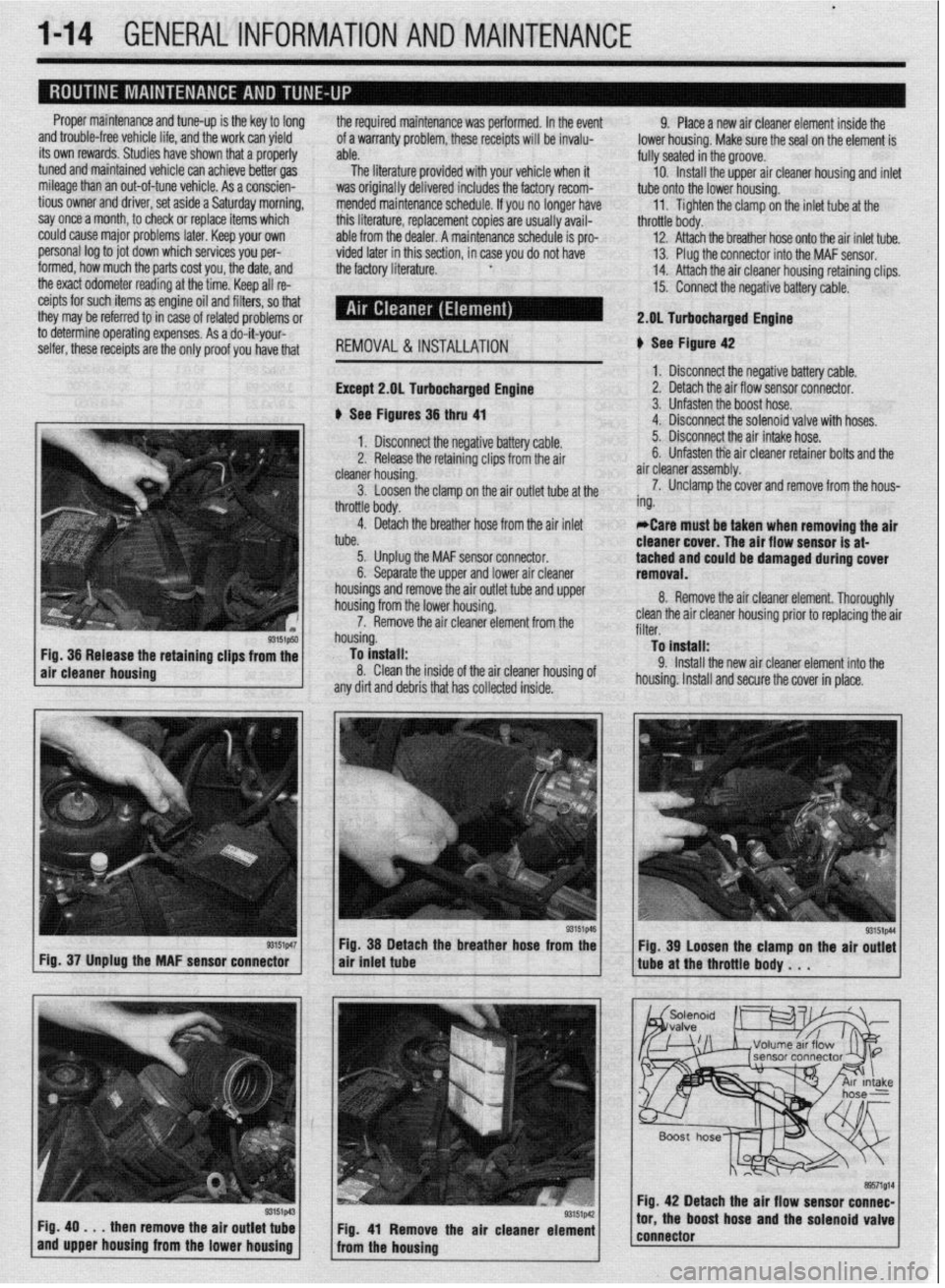
REMOVAL &INSTALLATION
Except 2.gL Turbocharged Engine
b See Figures 36 thru 41 9. Place a new air cleaner element inside the
lower housing. Make sure the seal on the element is
fully seated in the groove.
10. Install the upper air cleaner housing and inlet
tube onto the lower housing.
11. Tighten the clamp on the inlet tube at the
throttle body.
12. Attach the breather hose onto the air inlet tube.
13. Plug the connector into the MAF sensor.
14. Attach the air cleaner housing retaining clips.
15. Connect the negative battery cable.
2.DL Turbocharged Engine
b See Figure 42
1. Disconnect the negative battery cable.
2. Detach the air flow sensor connector.
3. Unfasten the boost hose.
4. Disconnect the solenoid valve with hoses.
93151p50 Fig. 36 Release the retaining clips from the
air cleaner housing
r3151p47 Fig. 37 Unplug the MAF sensor connector
Fig. 49
. . . then remove the air outlet tube
and upper housing from the lower housing 1. Disconnect the negative battery cable. 5. Disconnect the air intake hose.
2. Release the retaining clips from the air 6. Unfasten tie air cleaner retainer bolts and the
cleaner housing. air cleaner assembly.
3. Loosen the clamp on the air outlet tube at the 7. Unclamp the cover and remove from the hous-
throttle body. ing.
4. Detach the breather hose from the air inlet
tube. *Care must be taken when removing the air
cleaner cover. The air flow sensor is at-
5. Unplug the MAF sensor connector.
6. Separate the upper and lower air cleaner tached and could be damaged during cover
removal.
housings and remove the air outlet tube and upper
housing from the lower housing.
7. Remove the air cleaner element from the
housing.
To install:
8. Clean the inside of the air cleaner housing of
any dirt and debris that has collected inside. 8. Remove the air cleaner element. Thoroughly
clean the air cleaner housing prior to replacing the air
filter.
To install:
9. Install the new air cleaner element into the
housing. Install and secure the cover in place.
Fig. 38 Detach the breather hose from the
air tniet tube
Fig. 41 Remove the air cleaner element
from the housing Fig. 39 Loosen the clamp on the air outlet
tube at the throttle body . . .
Fig. 42 Detach the air flow sensor connec-
tor, the boost hose and the solenoid valve
connector
Page 15 of 408
*
l-16 GENERALINFORMATIONAND MAINTENANCE
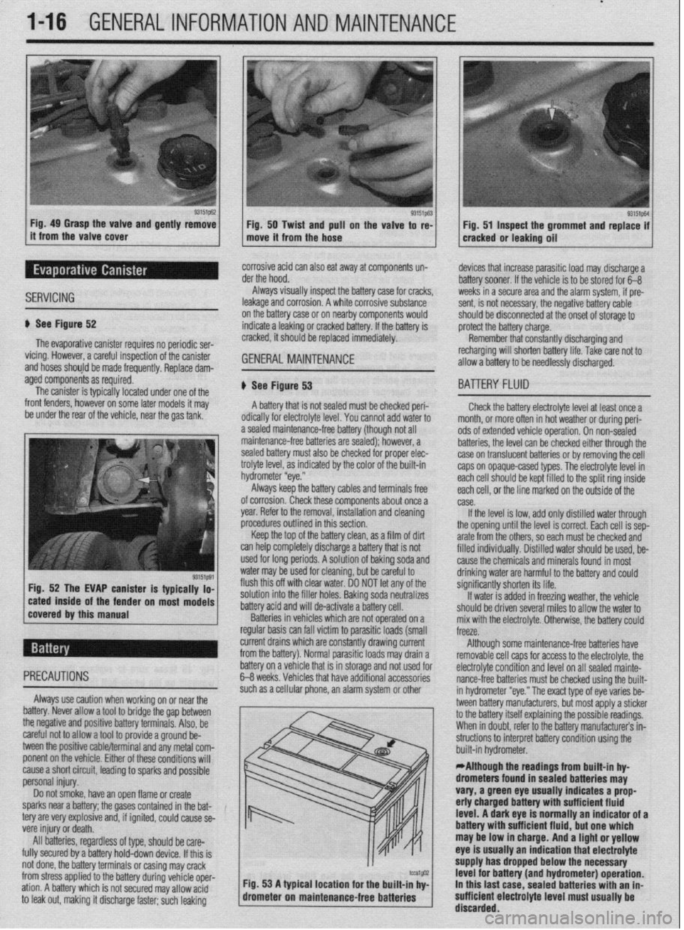
Fig. 49 Grasp the valve and gently remove
Fig. 50 Twist and pull on the valve to re-
it from the valve cover
move it from the hose Fig. 51 Inspect the grommet and replace if
cracked or leaking oil
SERVICING
corrosive acid can also eat away at components un-
der the hood.
Always visually inspect the battery case for cracks,
leakage and corrosion. A white corrosive substance
u See Figure 52
The evaporative canister requires no periodic ser-
vicing. However, a careful inspection of the canister
and hoses should be made frequently, Replace dam- on the battery case or on nearby components would
indicate a leaking or cracked battery. If the battery is
cracked, it should be replaced immediately. GENERALMAINTENANCE '_
devices that increase parasitic load may discharge a
battery sooner. If the vehicle is to be stored for 6-B
weeks in a secure area and the alarm system, if pre-
sent, is not necessary, the negative battery cable
should be disconnected at the onset of storage to
protect the battery charge.
Remember that constantly discharging and
recharging will shorten battery life. Take rare not to
allow a battery to be needlessly discharged.
aged components as required.
The canister is typically located under one of the
front fenders, however on some later models it may
be under the rear of the vehicle, near the gas tank,
r on most models # See Figure 53
A battery that is not sealed must be checked peri-
odically for electrolyte level. You cannot add water to
a sealed maintenance-free battery (though not all
maintenance-free batteries are sealed); however, a
sealed battery must also be checked for proper elec-
trolyte level, as indicated by the color of the built-in
hydrometer “eye.”
Always keep the battery cables and terminals free
of corrosion. Check these components about once a
year. Refer to the removal, installation and cleaning
procedures outlined in this section,
Keep the top of the battery clean, as a film of dirt
can help completely discharge a battery that is not
used for long periods. A solution of baking soda and
water may be used for cleaning, but be careful to
flush this off with clear water. DO NOT let any of the
solution into the filler holes. Baking soda neutralizes
battery acid and will de-activate a battery cell.
Batteries in vehicles which are not operated on a
regular basis can fall victim to parasitic loads (small
BA-ITERY FLUID
Check the battery electrolyte level at least once a
month. or more often in hot weather or during peri-
ods of extended vehicle operation. On non-sealed
batteries, the level can be checked either through the
case on translucent batteries or by removing the cell
caps on opaque-cased types. The electrolyte level in
each cell should be kept filled to the split ring inside
each ceil, or the line marked on the outside of the
case.
If the level is low, add only distilled water through
the opening until the level is correct. Each cell is sep-
arate from the others, so each must be checked and
filled individuallv. Distilled water should be used, be-
cause the chemicals and minerals found in most
drinking water are harmful to the battery and could
significantly shorten its life.
If water is added in freezing weather, the vehicle
should be driven several miles to allow the water to
mix with the electrolyte. Otherwise, the battery could
freeze.
current drains which are constantly drawing current
from the battery). Normal parasitic loads may drain a Although some maintenance-free batteries have
removable cell caos for access to the electrolyte, the
cause a short circuit, leading to sparks and possible
personal injury.
Do not smoke, have an open flame or create
sparks near a battery; the gases contained in the bat-
tery are very explosive and, if ignited, could cause se-
vere injury or death.
All batteries, regardless of type, should be care-
fully secured by a battery hold-down device. If this is
not done, the battery terminals or casing may crack
from stress applied to the battery during vehicle oper-
ation. A battery which is not secured may allow acid
to leak out, making it discharge faster; such leaking m / built-in hydrometer. .
*Although the readings from built-in hy-
drometers found in sealed batteries may
vary, a green eye usually indicates a prop
erly charged battery with sufficient fluid
level. A dark eye is normally an indicator of a
battery wlth sufficient fluid, but one which
may be low in charge. And a light or yellow
eye is usually an indication that electrolyte
supply has dropped below the necessary
tcu1@32 Fig. 53 A typical location for the built-in hv- level for battery (and hydrometer) operation.
drometer on maintenan
ce-free batteries ’ I In this last case. sealed batteries with an in-
sufficient electrolyte level must usually be
’ discarded.
Page 18 of 408
GENERAL INFORMATION AND MAlNTENANdE l-19
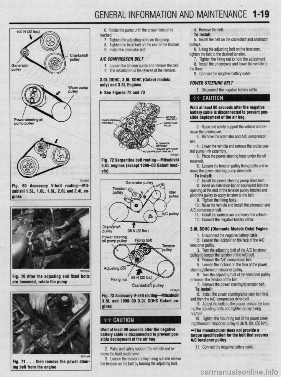
792UQ4 Fig. 69 Accessory V-belt routing-Mii
subishf 1.6L, 1.6L,-1.6L, 2.OL and 2.4L en
gines
33151PM Fig. 70 After the adjusting and fixed bolt!
are loosened, rotate the pump . . .
/ F$71t immtl$mm&a the power ::: 6. Rotate the pump until the proper tension is
reached.
7. Tighten the adjusting bolts on the pump.
8. Tighten the fixed bolt on the rear of the bracket.
9. Install the alternator belt.
A/r: COMPRESSOIl BEL f
1. Loosen the tension oullev and remove the belt.
2. The installation is the reverse of the removal.
.3.gL DGHC, 3.OL SOHC (Gaiant models
only) and 3.5L Engines 4. Remove the belt.
To install:
5. Install the belt on the crankshaft and alternator
pulleys.
6. Using the adjusting bolt on the tensioner,
tighten the belt to the desired tension.
7. Tighten the fixing nut to hold the adjustment.
8. Install the undercover and lower the vehicle to
_,
the tloor.
9. Connect the negative battery cable.
POWER SliEERlNG BEL f
6 See Figures 72 and 73 1. Disconnect the neaative batteN cah+P
-I
Wait at least 60 seconds after the negative
battery cable is disconnected to prevent poS-
sibie deployment of the air bag.
2. Raise and safely support the vehicle and re-
mob re the undercover.
3. Remove the alternator and NC compressor
belt.
4. Lower the vehicle and remove the cruise con-
trol oumn link iW%mblV. 79244Q.37
-- I-- r ---- - _I
Fig. 72 Serpentine belt routing-Mitsubishi 5. Place the power steering hose under the oil
reservoir.
3.OL engines (except 1696-00 Galant mod-
6.
Loosen the tension pulley fixing bolts and re-
els)
Generator pulP
1 move the power steering pump drive belt.
To install:
1 7. install the Dower steerina oumu r+r+v~ hp++
8. Insert an extension bar &eoufvaik;;t”f;;id‘he
opening at the end of the tension pulley bracket and
pivot the pulley to apply tension to the belt.
9. Tighten the fixing bolts.
10. Raise the vehicle and install the alternator and
compressor belt.
Il. Install the undercover and lower +hfi vph+r+p
.I,., .VII.“.Y.
12. Connect the negative battery cable.
I 3.OL SGHC (Diamante Models Onivl Enotne
I ,r ” 1. Disconnect the negative battery cable.
2.’ Loosen the lockbolt on the face nf the A/C _ __.- tensioner pulley.
3
Turn the adiustina bolt of the A/C +fincrnner
pulley to loosen the tension of the A/C belt.
4. Remove the A/C compressor belt.
5.
Loosen the locknut on the face of the power
to loosen the tc
7. Remov
Fig. 73 Accessory V-belt routing-Mitsubishi
3.5L and 1996-00 3.OL SOHC Galant en-
gines steering/alternator tensloner pulley.
6. Turn the adjusting bolt of the tensioner pulley
msion of the belt.
‘e the power steering/alternator belt.
To install:
8. Install the power steering/alternator belt first
.* .* . ,^
ssor drive belt. ana tnen tne A/ti compre:
9. Adjust the belts t+
ing the adjusting bolts anu
II~IIWII pueey tlxmg I the proper tension by turn-
A.:-L I-..-.. I,^, .’
nut/bolt.
10. Tighten the mounting nut of the power steer-
ing/alternator tensioner pulley to 36 ft. Ibs. (50 Nm).
Wait at least 60 seconds after the negative
battery cable is disconnected to prevent pos-
sible deployment of the air bag. -The manufacturer does not provide a
torque specification for the bolt that secures
A/C tensioner pulley.
2. Raise and safely support the vehicle and re- 11. Connect the negative battery cable.
move the front undercover.
3. Loosen the tension pulley fixing nut and relieve
the tension on the belt by turning the adjusting bolt.
Page 20 of 408
GENERALINFORMATIONAND MAINTENANCE l-21
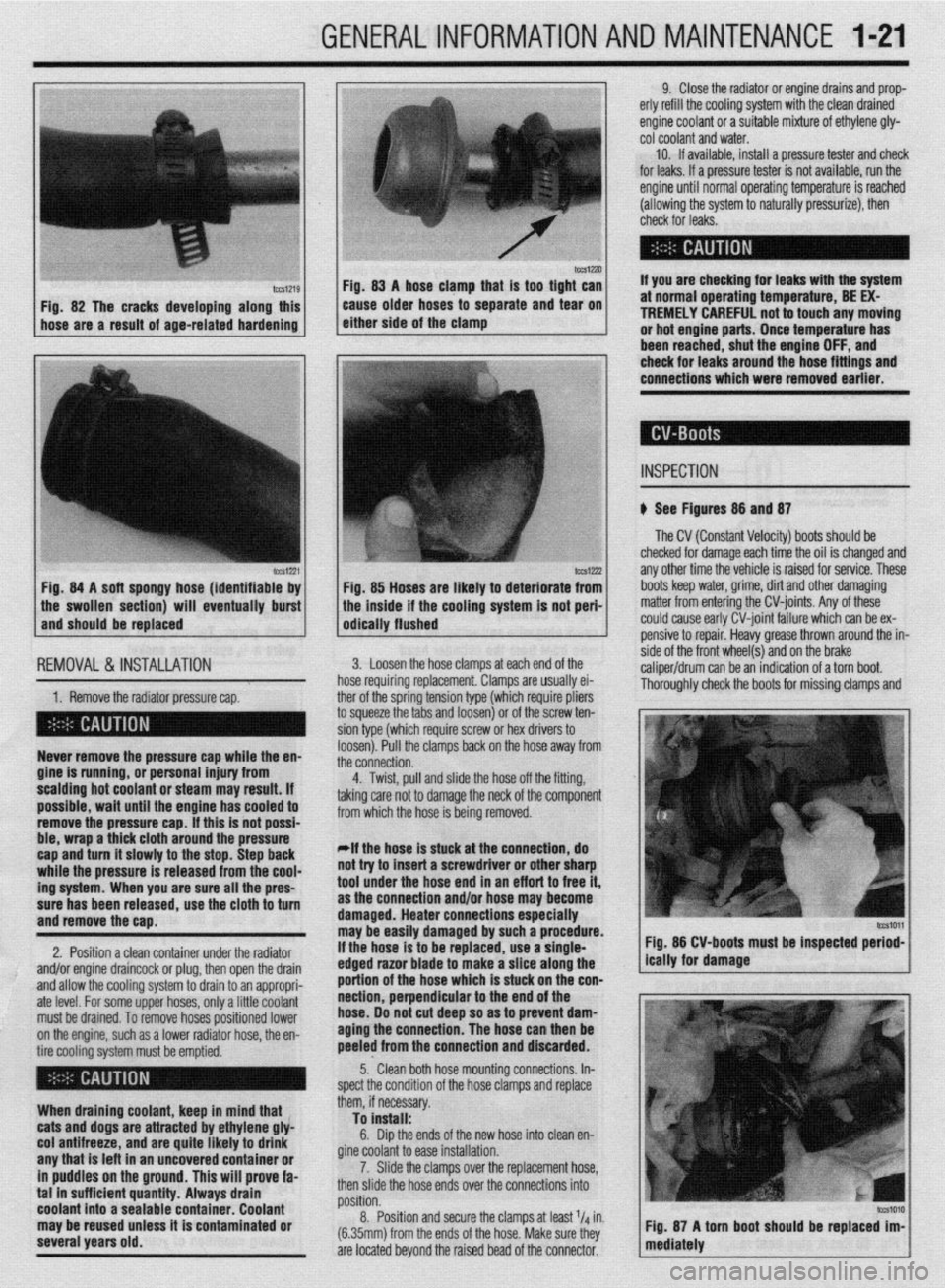
IWSIZXJ FM. 83 A hose clamn that is taa tiaht can
Fig. 82 The cracks developing along this
hose are a result of age-related hardening caise older hoses td separate and ‘iear on
either side of the clamp
lCCS1221 Fig. 84 A soft spongy hose (identifiable by
1 the swollen section) will eventually burst
and should be replaced
IEMOVAL &,INSTALLATION '
1. Remove the radiator pressure cap. her of the sorina tension tvoe (which reouire oliers
3 squeeze the 6bs and loosenj or of the’screw ten-
ion type (which require screw or hex drivers to
oosen). Pull the clamps back on the hose away from
he connection. Never remove the pressure cap while the en-
gine is running, or personal injury from
scalding hot coolant or steam may result. If
possible, wait until the engine has cooled to
remove the pressure cap. If this is not possi-
ble, wrap a thick cloth around the pressure
cap and turn it slowly to the stop. Step back
while the pressure is released from the cool-
ing system. When you are sure all the pres-
sure has been released, use the cloth to turn
and remove the cao.
2. Position a clean container under the radiator
and/or engine draincock or plug, then open the drain
and allow the cooling system to drain to an appropri-
ate level. For some upper hoses, only a little coolant
must be drained. To remove hoses positioned lower
on the engine, such as a lower radiator hose, the en-
tire cooling system must be emptied.
When draining coolant, keep in mind that
cats and dogs are attracted by ethylene gly-
col antifreeze, and are quite likely to drink
any that is left in an uncovered container or
in puddles on the ground. This will prove fa-
tal in sufficient quantity. Always drain
coolant into a sealable container. Coolant
may be reused unless it is contaminated or
several years old. 9. Close the radiator or engine drains and prop-
erly refill the cooling system with the clean drained
engine coolant or a suitable mixture of ethylene gly-
cot coolant and water.
10. If available, install a pressure tester and check
for leaks. If a pressure tester is not available, run the
engine until normal operating temperature is reached
(allowing the system to naturally pressurize), then
check for leaks.
If you are checking for leaks with the system
at normal operating temperature, BE EX-
TREMELY CAREFUL not to touch any moving
or hot engine parts. Once temperature has
been reached. shut the enaine OFF. and
Fig. 85 Hoses are likely to deteriorate from
the inside if the cooling system is not peri-
odically flushed check for leaks around the-hose fittings and
connections which were removed earlier.
INSPECTION
b See Figures 88 and 87
The CV (Constant Velocity) boots should be
checked for damage each time the oil is changed and
any other time the vehicle is raised for service. These
boots keep water, grime, dirt and other damaging
matter from entering the CV-joints. Any of these
could cause early CV-joint failure which can be ex-
pensive to repair. Heavy grease thrown around the in-
side of the front wheel(s) and on the brake
caliper/drum can be an indication of a torn boot.
Thorouahlv check the boots for missina clamos and 3. Loosen the hose clamps at each end of the
rose requiring replacement. Clamps are usually ei-
4. Twist, pull and slide the hose off the fitting,
sking care not to damage the neck of the component
rom which the hose is being removed.
*If the hose is stuck at the connection, do
lot try to insert a screwdriver or other sharp
ool under the hose end in an eff art to free it,
IS the connection and/or hose may become
lamaged. Heater connections especially
nay be easily damaged by such a procedure.
f the hose is to be replaced, use a single-
!dged razor blade to make a slice along the
lortion of the hose which is stuck on the con-
section, perpendicular to the end of the
lose. 00 not cut deep so as to prevent dam-
aging the connection. The hose can then be
keeled from the connection and discarded. Fig. 86 CV-boots must be inspected period-
5.. Clean both hose mounting connections. In-
,pect the condition of the hose clamps and replace
hem, if necessary.
To install:
6. Dip the ends of the new hose into clean en-
fine coolant to ease installation.
7. Slide the clamps over the replacement hose,
hen slide the hose ends over the connections into
rosition.
8. Position and secure the clamps at least l/d in.
6.35mm) from the ends of the hose. Make sure they
Ire located beyond the raised bead of the connector.