warning light MITSUBISHI DIAMANTE 1900 Repair Manual
[x] Cancel search | Manufacturer: MITSUBISHI, Model Year: 1900, Model line: DIAMANTE, Model: MITSUBISHI DIAMANTE 1900Pages: 408, PDF Size: 71.03 MB
Page 7 of 408
.
l-8 GENERALINFORMATIONAND MAINTENANCE
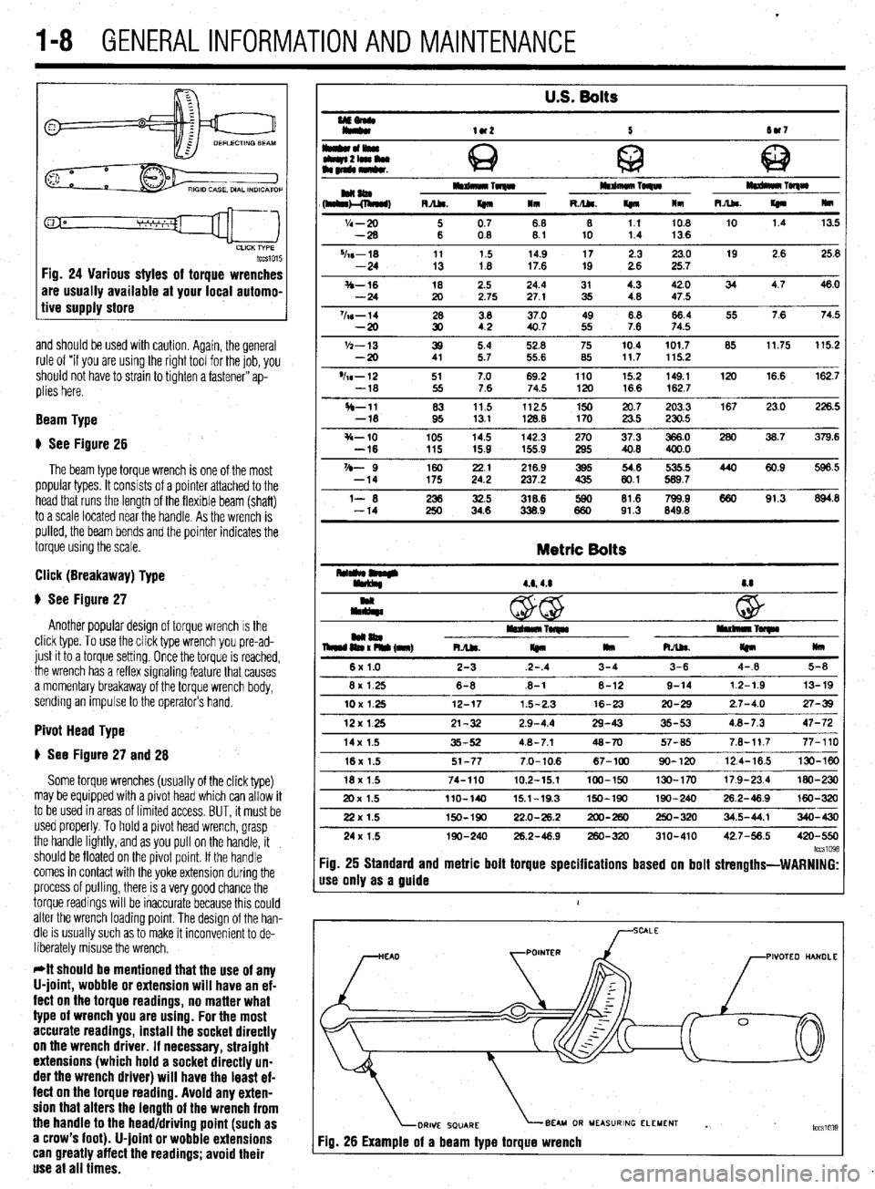
tccsio15 Fig. 24 Various styles of torque wrenches
are usually available at your local automo-
tive supply store
and should be used with caution. Again, the general
rule of “if you are using the right tool for the job, you
should not have to strain to tighten a fastener” ap-
plies here.
Beam Type
# See Figure 26
The beam type torque wrench is one of the most
popular types. It consists of a pointer attached to the
head that runs the length of the flexible beam (shaft)
to a scale located near the handle. As the wrench is
pulled, the beam bends and the pointer indicates the
torque using the scale.
Click (Breakaway) Type
$ See Figure 27
Another popular design of torque wrench IS the
click type. To use the click type wrench you pre-ad-
just it to a torque setting. Once the torque is reached,
the wrench has a reflex signaling feature that causes
a momentary breakaway of the torque wrench body,
sending an impulse to the operator’s hand.
Pivot Head Type
# See Figure 27 and 28
Some torque wrenches (usually of the click type)
may be equipped with a pivot head which can allow it
to be used in areas of limited access. BUT, it must be
used properly. To hold a pivot head wrench, grasp
the handle lightly, and as you pull on the handle, it
should be floated on the pivot point. If the handle
comes in contact with the yoke extension during the
process of pulling, there is a very good chance the
torque readings will be inaccurate because this could
alter the wrench loading point. The design of the han-
dle is usually such as to make it inconvenient to de-
liberately misuse the wrench.
*It should be mentioned that the use of any
U-joint, wobble or extension will have an ef-
fect on the torque readings, no matter what
type of wrench you are using. For the most
accurate readings, install the socket directly
on the wrench driver. If necessary, straight
extensions (which hold a socket directly un-
der the wrench driver) will have the least ef-
fect on the torque reading. Avoid any exten-
sion that alters the length of the wrench from
the handle to the head/driving point (such as
a crow’s foot). U-joint or wobble extensions
can greatly affect the readings; avoid their
use at all times.
U.S. Bolts
UEonlr
Iy*
lU2 5 tw7
I*cll*olwu
Q c
tbqn2lamlu
am~mkr. @ 63
HaaIm Toqw mdmuo TORW
(h&l!&, RA&. m 111 R./U. If410 lm m TolqW
R.Abs.
I(n Hm
'I4 - 20 i 0.7 68 8 1.1 10.8 10 1.4 13.5
-28 08 8.1 10 1.4 13.6
%s-18 11 1.5 14.9 17 2.3 23.0 19 2.6 25.8
-24 13 1.8 17.6 19 2.6 25.7
S-16 18 2.5 24.4 31 4.3 42.0 34 4.7 46.0
-24 20 2.75 27.1 35 4.8 47.5
%s-14 28 3.8 37.0 49 8.8 66.4 55 7.6 74.5
-20 30 42 40.7 55 7.6 74.5
'h-13 39 5.4 52.8 75 10.4 101.7 85 11.75 115.2
-20 41 5.7 55.6 85 117 115.2
'h-12 51 7.0 69.2 110 15.2 149.1 120 16.6 162.7
-18 55 7.6 74.5 120 16.6 162.7
H-11 83 11.5 112.5 150 20.7 203.3 167 23.0 226.5
-18 95 13.1 128.8 170 23.5 230.5
s-10 105 14.5 142.3 270 37.3 366.0 280 36.7 379.6
-16 115 15.9 155.9 295 40.8 400.0
VD- 9 160 2.: 216.9 395 54.6 535.5 440 60.9 596.5
-14 175 237.2 435 80.1 589.7
l- 6 iti 32.5 318.6 lE 81.6 799.9 660 91.3 894.8
-14 34.6 338.9 91.3 849.8
Metric Bolts
4.6,4.8 8.8
c
@ w
mm04 iEn% (nnr) I*rdn*lrTwlr rullllllnl~
RJU.
I(n llm RAk
m mu
6x1.0 2-3 2-.4 3-4 3-6 4-.8 5-8
8x 1.25 6-8 .6-l 8-12 9-14 12-1.9 13-19
10X1.25 12-17 1.5-2.3 16-23 20-29 2.7-4.0 27-39
12x125 21-32 2.9-4.4 29-43 35-53 4.8-7.3 47-72
14x 1.5 35-52 4.8-7.1 48-70 57-65 7.8-11.7 77-110
16x 1.5 51-77 7.0-10.6 67-100 90-120 12.4-16.5 130-W
18x 1.5 74-110 10.2-15.1 100-150 130-170 17.9-23.4 MO-230
20x 1.5 llO-140 15.1-19.3 150-190 190-240 26.2-46.9 160-320
22x 1.5 150-190 22.0-26.2 200-260 250-320 34.5-44.1 340-430
24x 1.5 190-240 26.2-48.9 260-320 310-410 42.7-56.5 420-550
lccs1098 :ig. 25 Standard and metric bolt torque specifications based on bolt strengths-WARNING:
Ise only as a guide
1
PIVOTEO HANDLE
BEAU OR MEASURING ELEMENT
Yg. 26 Example of a beam type torque wrench . tccslo3~
Page 59 of 408
.
2-12 ENGINEELECTRICAL
*This section describes the operating prina
ciples of sending units, warning lights and
gauges. Sensors which provide information
to the Enafne Control Unit (ECU) or Electronic
or Power&in Control Module (FCM/PCM) are
covered in Section 4 of this manual.
Instrument panels contain a number of indicating
devices (gauges and warning lights). These devices
are composed of two separate components. One is
the sending unit, mounted on the engine or other re-
mote part of the vehicle, and the other is the actual
gauge or light in the instrument panel.
Several types of sending units exist, however most
can be characterized as being either a pressure type
or a resistance type. Pressure type sending units
convert liquid pressure into an electrical signal which
is sent to the gauge. Resistance type sending units
are most often used to measure temperature and use
variable resistance to control the current flow back to
the indicatinq device. Both types of sendinq units are
connected inseries by a wimto the batteryithiough
the ignition switch). When the ignition is turned ON,
current flows from the battery through the indicating
device and on to the sending unit.
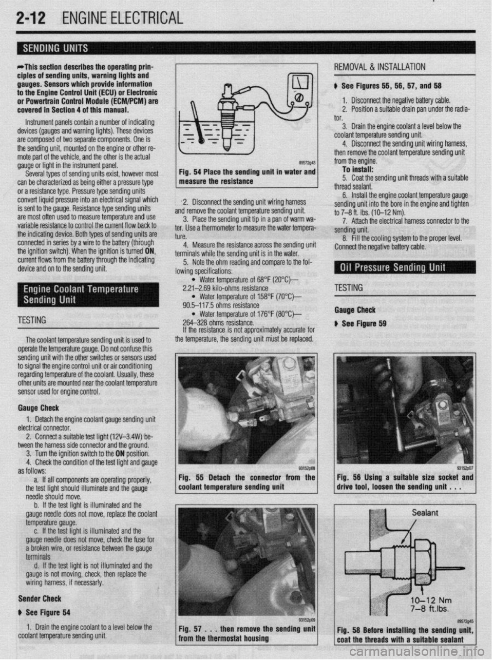
89572$43 Fig. 54 Place the sending unit in water and
measure the resistance
2. Disconnect the sending unit wiring harness
and remove the coolant temperature sending unit.
3. Place the sending unit tip in a pan of warm wa-
ter. Use a thermometer to measure the water tempera-
tl KP
L”,“.
4. Measure the resistance across the sending uni
terminals while the sending unit is in the water.
5. Note the ohm reading and compare to the fol-
lowing specifications: i, 56, 57, and 56
1. Disconnect the negative battery cable.
2. Position a suitable drain pan under the radia-
tor.
3. Drain the engine coolant a level below the
coolant temperature sending unit.
4. Disconnect the sending unit wiring harness,
then remove the coolant temperature sending unit
from the engine.
To install:
5. Coat the sending unit threads with a suitable
thread sealant.
6. Install the engine coolant temperature gauge
sending unit into the bore in the engine and tighten
to 7-8 ft. Ibs. (10-12 Nm).
7. Attach the electrical harness connector to the
sendina unit.
8. fill the cooling system to the proper level.
:onnect the negative battery cable.
l Water temperature of 68°F (2O”C)-
2.21-2.69 kilo-ohms resistance
l Water temperature of 158°F (7O’Ck
90.5-117.5 ohms resistance
TESTING l Water temperature of 176°F (8O”C)-
264-328 ohms resistance.
The coolant temperature sendina unit is used to
operate the temperature gauge. Donot confuse this
sending unit with the other switches or sensors used
to signal the engine control unit or air conditioning
regarding temperature of the coolant. Usually, these
other units are mounted near the coolant temoerature
sensor used for engine control. If the resistance is not approximately accurate for
the temperature, the sending unit must be replaced.
Gauge Check
1. Detach the engine coolant gauge sending unit
electrical connector.
2. Connect a suitable test liaht (12V-3.4W) be-
tween the harness side connector and the around.
I
3. Turn the ignition switch to the ON position.
4. Check the condition of the test light and gauge
as follows:
a. If all components are operating properly,
the test light should illuminate and the gauge
needle should move.
b. If the test light is illuminated and the
gauge needle does not move, replace the coolant
temperature gauge.
c. If the test light is illuminated and the
gauge needle does not move, check the fuse for
a broken wire, or resistance between the gauge
terminals
d. If the test light is not illuminated and the
gauge is not moving, check, then replace the
wiring harness, if necessar!y.
Sender Check
p See Figure 64
1. Drain the engine coolant to a level below the
coolant temperature sending unit Fig. 55 Detach the connector from the
coolant temperature sending unit
'ESTING
tauga Check
See Ftgure 69
Page 149 of 408
the temperature of the gas passing through +h
control valve. It converts the detected temf
Ierature
into an electrical voltage signal which is sent the ve-
hicle’s Powertrain Control Module (PCM). If the cir-
cuit of the EGR temperature sensor is broken, the
warning light will come on.
1. Remove the EGR temperature sensor from the
engine.
2. Place the EGR sensor into water. While in-
creasing the temperature of the water, measure the
sensor resistance. Compare the values to following
specifications:
a. 122°F 50°C
b. 212°F 100” )-11-14 kohms resistance
t P O-83 kohms resistance
3. If the resistance obtained varies significantly ,
.,. . .
i, replace the sensor, nom specmcaoom
Thermal Vacuum Valva
therm0 valve.
2. Connect a hand held vacuum pump to the vac-
uum hose on the therm0 valve.
3. Apply vacuum and check the air passage
through the therm0 vOrL’n %ults to the fnrm
lowinq specifications:
ant temperature of 122°F
vacuum leaks
lant temoerature of 176’F 4 n;rm.nnnn+ +h.n s,r,,~,,,,rn hnm frnm ‘h.n +hrotle
body EGR vacuum nipple. Connect a hand-held
vac-
uum pump to the nipple.
2. Start the engine, then slowly raise the speed
and compare with the following specifications.
a. For 1990-93 vehides, check to be sure the
vacuum raised proportionally with the rise in en-
gine s eed.
b. Ior 199450 vehicles, the vacuum reading
on the pump should remain constant.
EGR Solenoid
1990-93 L’EHICL ES
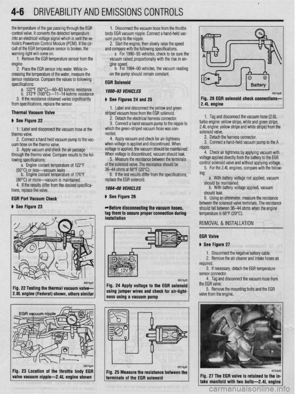
# See Figures 24 and 25
1. Label and disconnect the yellow and green
striped vacuum hose from the EGR solenoid.
netted.
4. Apply vacuum and check for air-tightness
when voltage is applied and discontinued. When
voltage is applied, the vacuum should be maintained.
When voltage is discontinued, vacuum should leak.
5. Measure the resistance between the terminals
of the solenoid valve. The resistance should be
36-44 ohms at 68°F (20°C).
6. If the test results differ from the soecifications.
4-6 DRIVEABILITYAND EMISSIONSCONTROLS
Fig. 26 EGR solenoid
check connections-
# See Figure 22
1. Label and disconnect the vacuum hose at the 2. Detach the electrical harness connector.
3. Connect a hand vacuum pump to the nipple to
which the green-striped vacuum hose was con-
(80°C) 0; more-vacuum is maintained
4. If the results differ from the desired specifica-
tions, replace the valve.
EGR Port Vacuum Check
+ See Figure 23 replace the EGR solenoid.
1994-00 VEHICLES
# See Figure 26
*Before disconnecting the vacuum hoses,
tag them to assure proper connection during
. . ** *. 1. Tag and disconnect the vacuum hose (2.OL
turbo engine: yellow stripe, white and green stripe,
2.4L engine: yellow stripe and white stripe) from the
solenoid valve.
2. Detach the harness connector.
3. Connect a hand-held vacuum pump to the A
nipple.
4. Check air tightness by applying vacuum with
voltage applied directly from the battery to the EGR
control solenoid valve and without applying voltage.
5. For the 2.4L engines, compare with the follow-
ing:
. .
roltage not applied, vacuum a. With battery
should be maintainr
b. With battery
.I III I
snoura
iea~.
sd. -
/oltage applied, vacuum
6. Using an ohmmeter, measure the resistance
between the solenoid valve terminals. The resistance
should fall between 36-44 ohms when the enaine
temperature is 68°F (20°C).
REMOVAL&INSTALLATION
EGR Valve
iI See Figure 27 mslatlanon
1 I Disconnect the negative battery cable.
2. Remove the air cleaner and intake hoses as
required.
3. If necessary, detach the EGR temperature
sensor connector.
4. Tag and disconnect the vacuum hose from
the EGR valve.
5. Remove the mounting bolts and the EGR
2.OL engine (Federal) shown, others similar
valve from the engine.
Fig. 27 The EGR valve is retained to t
take manifold with two bolts-2.4L e
Page 169 of 408
4-26 DRIVEABILITYAND EMISSIONS CONTROLS
The Powertrain Control Module (PCM) monitors
the signals of input and output sensors, some all the
time and others at certain times and processes each
signal. When the PCM notices that an irregularity has
continued for a specified time or longer from when
the irregular signal was initially monitored, the PCM
judges that a malfunction has occurred and will
memorize the malfunction code. The code is then
stored in the memory of the PCM and is accessible
through the data link (diagnostic connector) with the
use of an electronic scan tool or a voltmeter.
CHECK ENGINE/MALFUNCTION
INDICATOR LIGHT
Among the on-board diagnostic items, a check
engine/malfunction indicator light comes on to notify
the driver of a emission control component irregular-
ity. If the irregularity detected returns to normal or the
PCM judges that the component has returned to nor-
mal, the check engine/malfunction indicator light will
be turned off Moreover, if the ignition is turned OFF
and then the engine is restarted, the check
engine/malfunction indicator light will not be turned
on unttl a malfunction is detected.
The check engine/malfunction indicator light will
come on immediately after the ignition switch is
turned ON. The light should stay lit for 5 seconds
and then will go off. This Indicates that the check en-
gine/malfunction indicator lamp is operating nor-
mally. This does not signify a problem with the sys-
tem.
*The check engine/malfunction indicator
lamp will come on when the terminal for the
ignition timing adjustment is shorted to
ground. Therefore, it is not abnormal that the
light comes on even when the terminal for ig-
nition timing is shorted at time of ignition
timing adjustment.
To test the light, perform the following:
1. Turn the ignition switch ON. Inspect the check
engine/malfunction indicator lamp for Illumination.
2. The light should be lit for 5 seconds and then
should go out.
3. If the lamp does not illuminate, check for open
circuit In the harness, blown fuse or blown bulb.
SERVICE PRECAUTIONS
l Before attachrng or detaching the PCM harness
connectors, make sure the ignition switch is OFF and
the negative battery cable is disconnected to avoid
the possibility of damage to the PCM.
l When performing PCM input/output signal di-
agnosis, remove the pin terminal retainer from the
connectors to make it easier to insert tester probes
into the connector.
l When attaching or detaching pin connectors ,
from the PCM, take care not to bend or break any pin
terminals. Check that there are no bends or breaks on
PCM pin terminals before attempting any connec-
tions.
l Before replacing any PCM, perform the PCM
input/output signal diagnosis to make sure the PCM
is functioning properly.
l When measuring supply voltage of PCM-con-
trolled components with a circuit tester, separate 1
tester probe from another. If the 2 tester probes acci-
dentally make contact with each other during mea-
surement, a short circuit WIII result and damage the
PCM.
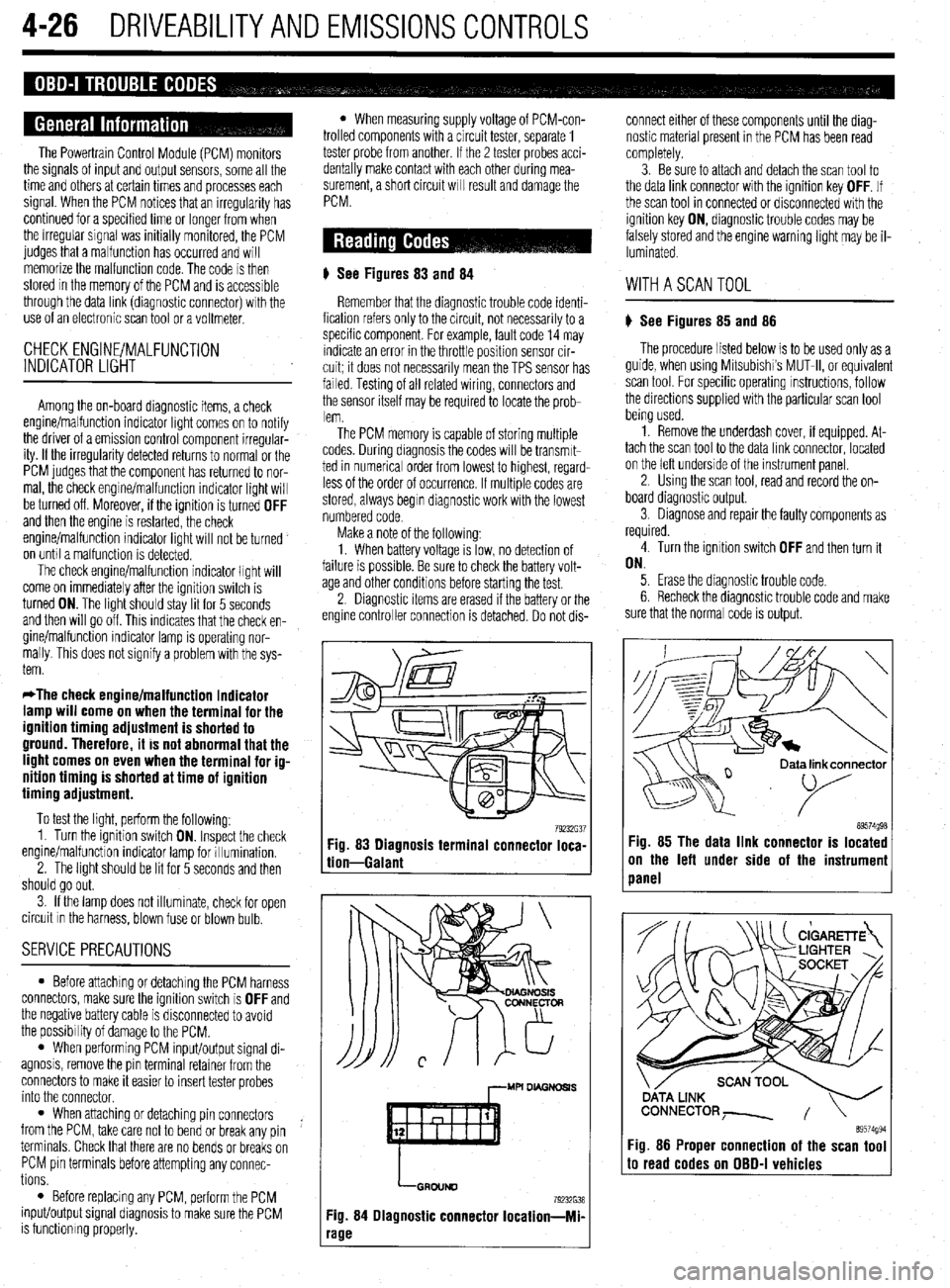
# See Figures 83
and 84
Remember that the diagnostic trouble code identi-
fication refers only to the circuit, not necessarily to a
specific component. For example, fault code 14 may
indicate an error in the throttle position sensor cir-
cuit; it does not necessarily mean the TPS sensor has
failed Testing of all related wiring, connectors and
the sensor itself may be required to locate the prob-
lem.
The PCM memory is capable of storing multiple
codes. During diagnosis the codes will be transmlt-
ted in numerical order from lowest to highest, regard-
less of the order of occurrence. If multiple codes are
stored, always begin diagnostic work with the lowest
numbered code
Make a note of the following:
1. When battery voltage IS low, no detection of
failure is possible. Be sure to check the battery volt-
age and other conditions before starting the test.
2. Diagnostic items are erased if the battery or the
engine controller connection is detached. Do not dis- connect either of these components until the diag-
nostic material present in the PCM has been read
completely.
3. Be sure to attach and detach the scan tool to
the data link connector with the ignition key OFF. If
the scan tool in connected or disconnected with the
ignition key ON, diagnostic trouble codes may be
falsely stored and the engine warning light may be il-
luminated. WITHASCANTOOL
) See Figures 85 and 86
The procedure listed below is to be used only as a
guide, when using Mitsubishi’s MUT-II, or equivalent
scan tool. For specific operating instructions, follow
the directions supplied with the particular scan tool
bemg used.
1. Remove the underdash cover, if equipped. At-
tach the scan tool to the data link connector, located
on the left underside of the instrument panel.
2. Using the scan tool, read and record the on-
board diagnostic output.
3. Diagnose and repair the faulty components as
required
4. Turn the ignition switch OFF and then turn it
ON.
5. Erase the diagnostic trouble code.
6 Recheck the diaanostic trouble code and make
sure that the normal &de is output.
79232G37 89574g98 Fig. 83 Diagnosis terminal connector loca-
tion-Galant Fig. 85 The data link connector is located
on the left under side of the instrumeni
panel
,--MU DL4GNDSl.S
LGRDIJND
79232638
Fig. 84 Diagnostic connector Iocation-Mi-
‘age
ata link connector
89574994 Fig. 86 Proper connection of the scan tool to read codes on OBD-I vehicles
Page 222 of 408
CHASSIS ELECTRICAL 6-19
1. Disconnect the negative battery cable.
are all built into 1 multi-function combination
2. Remove the instrument cluster, as outlined 1. Disconnect the negative battery cable.
earlier in this section. switch that is mounted on the steering col-
2. Using a small screwdriver or other suitable
umn. Refer to Section 8 for procedures re-
3. Remove the retaining screws for the instrument tool, carefully pry the retaining clips from either side
garding the combination switch.
cluster lens and cover assembly. Remove the cover of the switch trim plate.
3.
and lens. Carefully pull the switch and trim plate out of
,
4. Remove the retaining screws for the gauge or the instrument panel.
4. Detach the electrical connectors and remove
warning lamp to be replaced, then remove the gauge
the switch.
or warning lamp.
REMOVAL&INSTALLATION : 5. The installation is the reverse of removal.
To install:
5. Place the gauge or warning lamp into place
and tighten the retaining screws. 1. Disconnect the negative battery cable.
6. Install the instrument cluster lens and cover 2. Using a suitable prytool, disengage the switch
assembly. retaining tabs.
REMOVAL &INSTALLATION 7. Install the instrument cluster. 3. Gently pull the switch from the instrument
8. Connect the negative battery cable. panel.
4. Detach the electrical connector and remove the *On all models the headlights, turn signals,
switch. and on some models, the cruise control func-
5. The installation is the reverse of removal. tion are all built into 1 multi-function combi-
nation switch that is mounted on the steerinq
REMOVAL &INSTALLATION column. Refer to Section 8 for procedures 6
garding the combination switch.
*The headlights, turn signals, dimmer
switch, horn switch, windshield
REMOVAL &INSTALLATION
wiper/washer, intermittent wiper switch and *
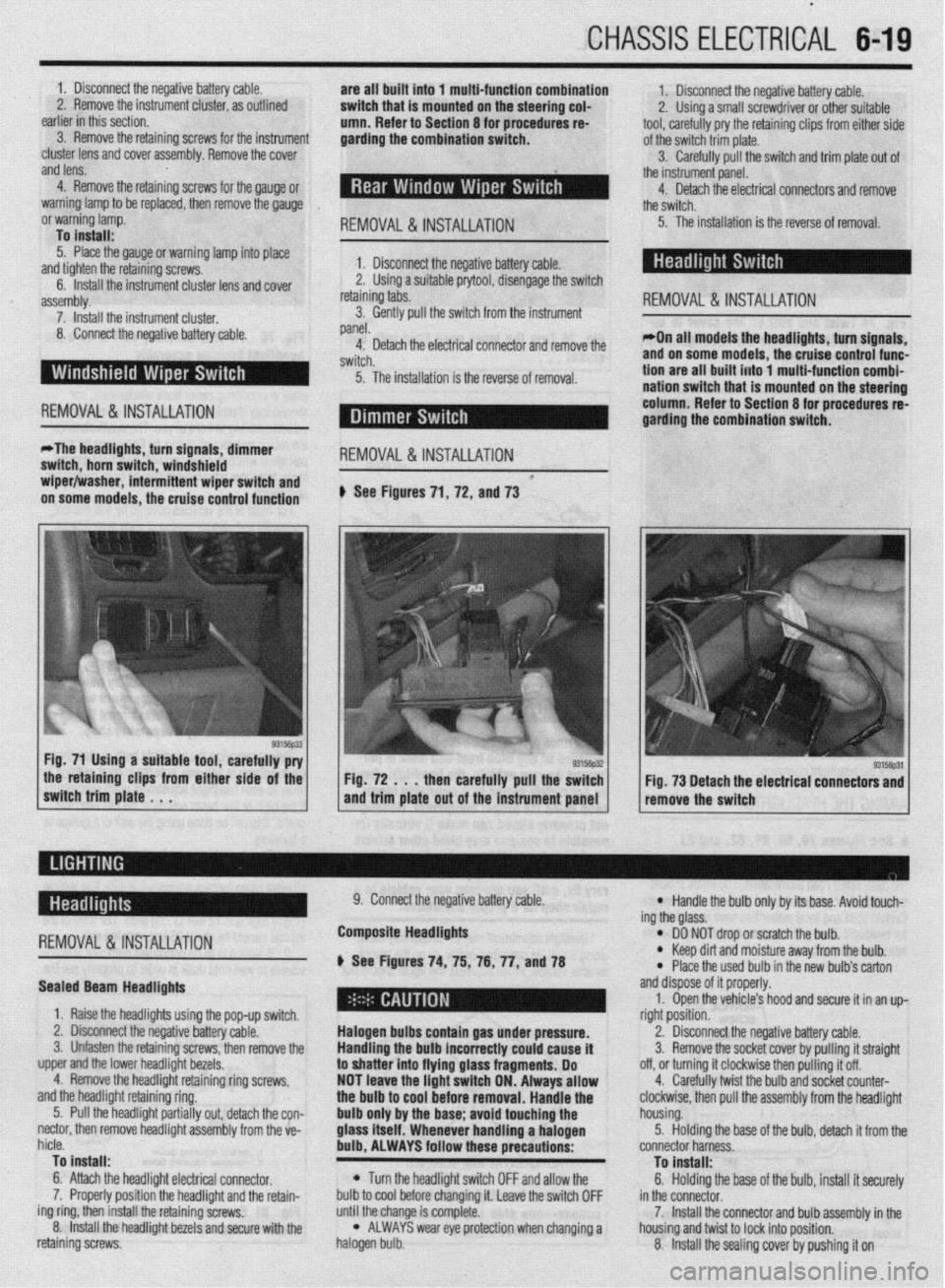
on some models, the cruise control function # See Figures 71, 72, and 73
the retaining clips from either side of the
switch trim plate . . . Fig. 72 . . . then carefully pull the switch
and trim plate out of the instrument panel Fig. 73 Detach the electrical connectors and
remove the switch
-
REMOVAL &INSTALLATION
Sealed Beam Headlights
1. Raise the headlights using the pop-up switch.
2. Disconnect the negative battery cable.
3. Unfasten the retaining screws, then remove the
upper and the lower headlight bezels.
4. Remove the headlight retaining ring screws,
and the headlight retaining ring.
5. Pull the headlight partially out, detach the con-
nectar, then remove headlight assembly from the ve-
hicle.
To install:
6. Attach the headlight electrical connector.
7. Properly position the headlight and the retain-
ing ring, then install the retaining screws.
8. Install the headlight bezels and secure with the
retaining screws. 9. Connect the negative battery cable.
Composite Headlights
6 See Figures 74, 75, 76, 77, anU78
Halogen bulbs contain gas under pressure.
Handling the
bulb incorrectly could cause it
to shatter into flying glass fragments. Do
NOT leave the light switch ON. Always allow
the bulb to cool before removal. Handle the
bulb only by the base; avoid touching the
glass itself. Whenever handling a halogen
bulb, ALWAYS follow these precautions:
l Turn the headlight switch OFF and allow the
bulb to cool before changing it. Leave the switch OFF
until the change is complete.
l ALWAYS wear eye protection when changing a
halogen bulb.
l Handle the bulb only by its base. Avoid touch-
ing the glass.
l DO NOT drop or scratch the bulb. l Keep dirt and moisture away from the bulb.
* Place the used bulb in the new bulb’s carton
and dispose of it properly.
1. Open the vehicle’s hood and secure it in an up-
right position.
2. Disconnect the negative battery cable.
3. Remove the socket cover by pulling it straight
off, or turning it clockwise then pulling it off.
4. Carefully twist the bulb and socket counter-
clockwise, then pull the assembly from the headlight
housing.
5. Holding the base of the bulb, detach it from the
connector harness.
To install:
6. Holding the base of the bulb, install it securely
in the connector.
7. Install the connector and bulb assembly in the
housing and twist to lock into position.
8. Install the sealing cover by pushing it on
Page 324 of 408
. . . ,.x ..-~ .-....,, _s_s”., .._ ” *
8-28 SUSPENSION AND STEERING
REMOVAL&INSTALLATION
199%93 Mirage 1994-00 Mirage and Galant
b See Figures 76 thru 85 the NEUTRAL mark on the clockspring with the mat-
f ing mark on the casing. Then, install the steering
wheel and tighten the new retaining nut to 29 ft. Ibs.
(40 Nm).
8. Install the air bag module.
1. Disconnect the negative battery cable.
2. Remove the horn pad from the steering wheel,
by pulling the lower end of the pad upward. Detach I
If aqui
arm it --.-.- ---.-...= .-r-.‘- -.. _..- ._.. - -
Failure to do so could result in severe per-
sonal injury and damage to vehicle. pped with an air bag, be sure to dls- hnfnra sfarfinn rmairs on the vehicle.
9. Connect the negative battery cable, turn the key
to the ON position; the SRS warning light should illu-
minate for seven seconds and go out.
1990-93 Galant
hbin butin connector.
3. Remove steering wheel retaining nut:
. . . .‘ .
a. .a I <.
4. Matcnmarlc me steering wneel to me snan.
5. Use a steering wheel puller to remove the
steering wheel.
Do not hammer on steering wheel to remove
it. The collapsible column mechanism may
ha rlsmwmd.
To install:
6. Line up the matchmarks and install the steer-
ing wheel to the shaft.
7. Ti flhten the steering wheel attaching nut to 29
ft. Ibs. (40 Nm).
8. Reconnect the horn connector and install the
horn pad.
9. Connect the neaative battetv cable. 1. Disarm the SRS system as outlined in Section 6.
^ m *I
sand the air bag module
.,A +L. m++-,g w,,eel,
*. I z. Remove me cover
mounting nut from behill” ~IK ~(G~G!I
3. To detach the connector of the clocKsprmfl
from the air bag module, press the air bag’s lock to-
ward the module to spread the lock open. While
holding lock in this position, use a small tipped pry-
ing tool to gently pry the connector from the module.
4. Remove the air bag module and store in a
clean, dry place with the pad cover facing up.
5. Matchmark the steering wheel to the shaft.
6. Remove the steering wheel retaining nut and
use a steering wheel puller to remove the wheel. Do
not use a hammer, or the collapsible mechanism in
the column could be damaged.
To install:
7. Confirm that the front wheels are in a straight-
ahead position. Center the clocksprinfl by aligning 1. Disconnect the negative battery cable.
2. Remove the horn oad from the steerino wheel
as follows:- - - - r d
a. For 1990-91 models only, the horn pad is
removed by pushing the pad upward, to release
the pad from the retaining clips. Detach horn but-
ton connector and remove the pad.
b.
For 1992-93 models only, remove the
screw from the bottom of the pad and push the
pad upward, to release the pad from the retaining
clips. Detach horn button connector and remove
the pad.
3. Remove steering wheel retaining nut.
4. Matchmark the steering wheel to the shaft.
5. Use a steering wheel puller to remove the
steering wheel.
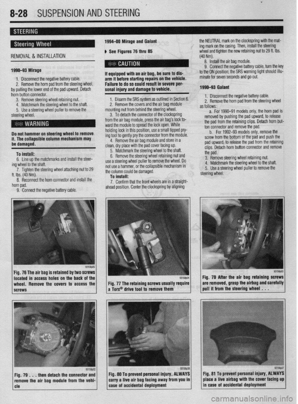
Fig. 76 The air bag is retained by two 8
located in access holes on the back
wheel. Remove the covers to access the
screws Fig. 78 After the air baa
retainino screws
Fig. 77 The retaining screws usually require are removed, grasp the airbag andiarefully
a Torx@ drive tool to remove them pull it from the steering wheel . . .
then detach the connector and Fig. 80 To prevent personal injury, ALWAYS fig. 81 To prevent personal Injury, ALWAYS
ove the air bag module from the vehi- carry a live air bag facing away from you in place a live airbag with the cover facing up
Page 325 of 408
SUSPENSION AND STEERING 8-29
i ’
Do not hamme i4 l-ha nnlhnr !r on steering wheel to remove
,,. , II= ,,,,,,Jfble column mechanism may REMOVALANDINSTALLATION
I
be damaged.
To install:
ing
7.
6. Line up the matchmarks and install the steer-
/heel to the shaft.
Tighten the steering wheel attaching nut to
25-33 ft. Ibs. (35-45 Mm).
8. Attach the horn connector and install the horn
pad.
9. Connect the negative battery cable.
Diamante The air bag system (SRS or SIR) must be dis-
armed before removing the steering wheel.
Failure to do so may cause accidental de-
ployment, property damage or personal in-
MY.
1 Rscnnnnd the nnmtivn hattm rJhle . I._“” . ..I_. . ..I *.-~ _...” ““.‘“‘, _““._. 2. If equipped, disable the air bag system.
3. Remove the steering wheel as outlined earlier
in this section.
Be sure to disarm the SRS (air bag
before starting repairs OI
to do so could result in p
death. DO NOT perform ;
cle until after 90 seconds has passed. The ai
bag system is designed to retain enough
short term voltage to make air bag deploy-
ment possible; I) system,
n the vehicle. Failure
lersonal injury or
any work on the vehi-
ir 4. For Diamante models, remove the hood lock
release handle.
5. Remove the knee protector panel under the
steering column, then the upper and lower column
covers.
6. For Diamante models, remove the lap cooler
and foot blower duct work as necessary. Carefully de-
non
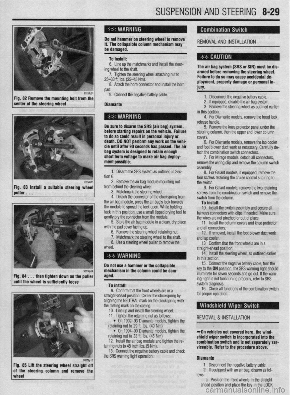
b. 1. Disarm the SRS system as outlined in Sec-
. . ^ I assembly. tach the combination switch connecto&.
8. -
7. For Mirage models, detach all connectors,
For Galant models, if equipped, remove the remove the wiring clip and remove the column switch
2. Remove the air bag module mounting nut
from behind the steering wheel.
3. Matchmark the steering wheel.
4. Detach the connector of the clockspring from
the air baq module, press the air baa’s lock towards four screws retaining the cruise control slip ring to
the switch.
9. For Galant models, remove the two retaining
screws from the combination switch and remove the
switch from the column.
Tn install: the modub to spread the lock open:While holding
lock in this position, use a small tipped prying tool to
gently pry the connector from the module.
5. Store the air bag module in a clean, dry place
..# ,I I I .
ut.
Iaft. wlrn me paa cover racmg up.
6. Remove the steering wheel retaining nl
7. Matchmark the steering wheel to the sl
8. Use a steering wheel puller to remove the
wheel. - . . - _-. . _
10. Install the switch assembly and secure all
harness connectors with clips if needed. Make sure
the wires are not pinched orout of place.
11. Install the column covers and knee protector
and all connectors.
12. If removed, install the foot blower duct work
anfl tan cnnler -..- .-
r --- ”
13. Confirm that the front wheels are in a
straight-ahead position.
14. Install the steering wheel, as outlined earlier
in thir
Do not use a hammer or the ~r”---‘~‘- 15. Connect the negative battery cable, turn the
key to the ON position, the SRS warning light should
NW down
rinntlv
wImpl* the puller
iem Fig. 84 . . . then tighte
until the wheel is suffL,,,,, lVvoV
To install:
0 Pnnfirm that thn frnnt whnalc ,?A in , .I. ““llllllll u,a, ,110 ll”lll I.ll~rJlJ CnIj 111 a
straight-ahead position. Center the clockspring by
aligning the NEUTRAL mark on the clockspring with
the mating mark on the casing.
10. Line up and install the steering wheel. illuminate for seven seconds and go out. If the warn-
ing light is not functioning properly, refer to SRS
s’ .’ ystem cllagnosls.
16. Check all functions of the combination switch
for proper operation.
wheel lows:
a. Position the front wheels in the straight
ahead position and place the key in the LOCK
93158p12 Fig. 85 Lift the steering wheel straight off
of the steering column and remove the 11. Tighten the retaining nut as follows:
REMOVAL &INSTALLATION
l On 1992-93 Diamante models, tighten the
nut to 29 ft. Ibs. (40 Nm) retammg I
l On
retaining I
12. lnstal
taining nuts 1
13. Conn
“... . ..” .‘“J...*.” ‘&.“WSJ Y..“.” . ..rn” VII”“..
the SRS warning light operation. 1994-00 Diamante models, tighten the
iut to 33 ft. Ibs. (45 Nm)
II the air bag module and tighten the r&
:o 48 inch Ibs. (5 Nm).
wt the rwnative hatim rahle ami rhwk
*On vehicles not covered here, the wind-
shield wiper switch is incorporated into the
combination switch and is not separately serl
viceable. Refer to the procedure
above.
Diamante
1. Disconnect the negative battery cable.
2. If equipped with an air bag, disarm as fol-
I” .L
Page 338 of 408
9-2 BRAKES
Hydraulic systems are used to actuate the brakes
of all modern automobiles. The system transports the
power required to force the frictional surfaces of the
braking system together from the pedal to the indi-
vidual brake units at each wheel. A hydraulic system
is used for two reasons.
First, fluid under pressure can be carried to all
parts of an automobile by small pipes and flexible
hoses without taking up a significant amount of room
or posing routing problems.
Second, a great mechanical advantage can be
given to the brake pedal end of the system, and the
foot pressure required to actuate the brakes can be
reduced by making the surface area of the master
cylinder pistons smaller than that of any of the pis-
tons in the wheel cylinders or calipers.
The master cylinder consists of a fluid reservoir
along with a double cylinder and piston assembly.
Double type master cylinders are designed to sepa-
rate the front and rear braking systems hydraulically
in case of a leak. The master cylinder converts me-
chanical motion from the pedal into hydraulic pres-
sure within the lines. This pressure is translated back
into mechanical motion at the wheels by either the
wheel cylinder (drum brakes) or the caliper (disc
brakes).
Steel lines carry the brake fluid to a point on the
vehicle’s frame near each of the vehicle’s wheels. The
fluid is then carried to the calipers and wheel cylin-
ders by flexible tubes in order to allow for suspen-
sion and steering movements.
In drum brake systems, each wheel cylinder con-
tains two pistons, one at either end, which push out-
ward in opposite directions and force the brake shoe
into contact with the drum.
In disc brake systems, the cylinders are part of the
calipers. At least one cylinder in each caliper is used
to force the brake pads against the disc.
All pistons employ some type of seal, usually
made of rubber, to minimize fluid leakage. A rubber
dust boot seals the outer end of the cylinder against
dust and dirt. The boot fits around the outer end of
the piston on disc brake calipers, and around the
brake actuating rod on wheel cylinders.
The hydraulic system operates as follows: When at
rest, the entire system, from the piston(s) in the mas-
ter cylinder to those in the wheel cylinders or
calipers, is full of brake fluid. Upon application of the
brake pedal, fluid trapped in front of the master cylin-
der piston(s) is forced through the lines to the wheel
cylinders. Here, it forces the pistons outward, in the
case of drum brakes, and inward toward the disc, in
the case of disc brakes. The motion of the pistons is
opposed by return springs mounted outside the
cylinders in drum brakes, and by spring seals, in disc
brakes.
Upon release of the brake pedal, a spring located
inside the master cylinder immediately returns the
master cylinder pistons to the normal position. The
pistons contain check valves and the master cylinder
I
has compensating ports drilled in it. These are un-
covered as the pistons reach their normal position.
The piston check valves allow fluid to flow toward the
wheel cylinders or calipers as the pistons withdraw.
Then, as the return springs force the brake pads or
shoes into the released position, the excess fluid
reservoir through the compensating ports. It is during the time the pedal is in the released position that any
fluid that has leaked out of the system will be re-
placed through the compensating ports.
Dual circuit master cylinders employ two pistons,
located one behind the other, in the same cylinder.
The primary piston is actuated directly by mechanical
linkage from the brake pedal through the power
booster. The secondary piston is actuated by fluid
trapped between the two pistons. If a leak develops in
front of the secondary piston, it moves forward until it
bottoms against the front of the master cylinder, and
the fluid trapped between the pistons will operate the
rear brakes. If the rear brakes develop a leak, the pri-
mary piston will move forward until direct contact
with the secondary piston takes place, and it will
force the secondary piston to actuate the front brakes.
In either case, the brake pedal moves farther when the
brakes are applied, and less braking power is avail-
able.
All dual circuit systems use a switch to warn the
driver when only half of the brake system is opera-
tional. This switch is usually located in a valve body
which is mounted on the firewall or the frame below
the master cylinder. A hydraulic piston receives pres-
sure from both circuits, each circuits pressure being
applied to one end of the piston. When the pressures
are in balance, the piston remains stationary. When
one circuit has a leak, however, the greater pressure
in that circuit during application of the brakes will
push the piston to one side, closing the switch and
activating the brake warning light.
In disc brake systems, this valve body also con-
tains a metering valve and, in some cases, a propor-
tioning valve. The metering valve keeps pressure
from traveling to the disc brakes on the front wheels
until the brake shoes on the rear wheels have con-
tacted the drums, ensuring that the front brakes will
never be used alone. The proportioning valve con-
trols the pressure to the rear brakes to lessen the
chance of rear wheel lock-up during very hard brak-
ing.
Warning lights may be tested by depressing the
brake pedal and holding it while opening one of the
wheel cylinder bleeder screws. If this does not cause
the light to go on, substitute a new lamp, make conti-
nuity checks, and, finally, replace the switch as nec-
essary.
The hydraulic system may
be checked for leaks by applying pressure to the pedal gradually and steadily.
If the pedal sinks very slowly to the floor, the system
has a leak. This is not to be confused with a springy
or spongy feel due to the compression of air within
the lines. If the system leaks, there will be a gradual
change in the position of the pedal with a constant
pressure.
Check for leaks along all lines and at wheel cylin-
ders. If no external leaks are apparent, the problem is
inside the master cylinder,
DISC BRAKES
Instead of the traditional expanding brakes that
press outward against a circular drum, disc brake
systems utilize a disc (rotor) with brake pads posi-
tioned on either side of it. An easily-seen analogy is
the hand brake arrangement on a bicycle. The pads
squeeze onto the rim of the bike wheel, slowing its
motion. Automobile disc brakes use the identical principle but apply the braking effort to a separate
disc instead of the wheel.
The disc (rotor) is a casting, usually equipped with
cooling fins between the two braking surfaces. This
enables air to circulate between the braking surfaces
making them less sensitive to heat buildup and more
resistant to fade. Dirt and water do not drastically af-
fect braking action since contaminants are thrown off
by the centrifugal action of the rotor or scraped off
the by the pads. Also, the equal clamping action of
the two brake pads tends to ensure uniform, straight
line stops. Disc brakes are inherently self-adjusting.
There are three general types of disc brake:
1. A fixed caliper.
2. A floating caliper.
3. A sliding caliper.
The fixed caliper design uses two pistons
mounted on either side of the rotor (in each side of
the caliper). The caliper is mounted rigidly and does
not move.
The sliding and floating designs are quite similar.
In fact, these two types are often lumped together. In
both designs, the pad on the inside of the rotor is
moved into contact with the rotor by hydraulic force.
The caliper, which is not held in a fixed position,
moves slightly, bringing the outside pad into contact
with the rotor. There are various methods of attaching
floating calipers. Some pivot at the bottom or top,
and some slide on mounting bolts. In any event, the
end result is the same.
DRUM BRAKES
Drum brakes employ two brake shoes mounted on
a stationary backing plate. These shoes are posi-
tioned inside a circular drum which rotates with the
wheel assembly. The shoes are held in place by
springs. This allows them to slide toward the drums
(when they are applied) while keeping the linings and
drums in alignment. The shoes are actuated by a
wheel cylinder which is mounted at the top of the
backing plate. When the brakes are applied, hydraulic
pressure forces the wheel cylinder’s actuating links
outward. Since these links bear directly against the
top of the brake shoes, the tops of the shoes are then
forced against the inner side of the drum. This action
forces the bottoms of the two shoes to contact the
brake drum by rotating the entire assembly slightly
(known as servo action). When pressure within the
wheel cylinder is relaxed, return springs pull the
shoes back away from the drum.
Most modern drum brakes are designed to self-
adjust themselves during application when the vehi-
cle is moving in reverse. This motion causes both
shoes to rotate very slightly with the drum, rocking
an adjusting lever, thereby causing rotation of the ad-
justing screw. Some drum brake systems are de-
signed to self-adjust during application whenever the
brakes are applied. This on-board adjustment system
reduces the need for maintenance adjustments and
keeps both the brake function and pedal feel satisfac-
tory.
POWER BOOSTERS
Virtually all modern vehicles use a vacuum as-
sisted power brake system to multiply the braking
force and reduce pedal effort. Since vacuum is always
available when the engine is operating, the system is
Page 361 of 408
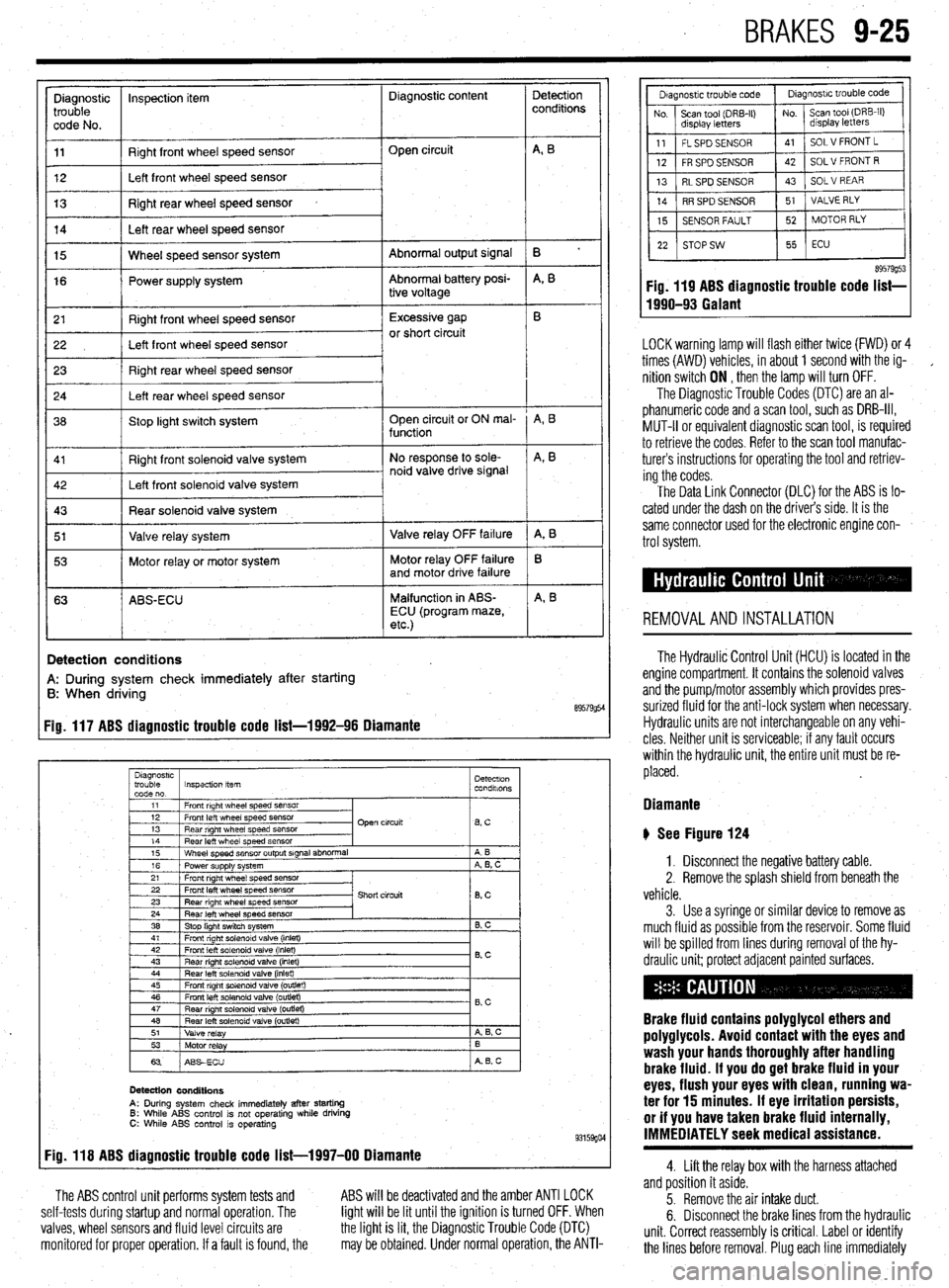
BRAKES 9-25
Diagnostic inspection item Diagnostic content
trouble
code No.
11 Right front wheel speed sensor
12 Left front wheel speed sensor Open circuit
13 Right rear wheel speed sensor
14 Left rear wheel speed sensor
Abnormal output signal
Abnormal battery posi-
tive voltage 15 Wheel speed sensor system
16 Power supply system
r 21
I Right front wheel speed sensor 1 Excessive gap
22 I Left front wheel speed sensor or short circuit
23 Right rear wheel speed sensor
24 Left rear wheel speed sensor
36 Stop light switch system Open circuit or ON mal-
function
Right front solenoid valve system
I 5’ I Valve relay system 1 Valve relay OFF failure
I 53 1 Motor relay or motor system Motor relay OFF failure
and motor drive failure
63 ABS-ECU Malfunction in ABS-
ECU (program maze,
etc.)
I
!
Detection
conditions
B ’
A, B
A, B
A, B
A, 8
B
A, B
Detection conditions
A: During system check immediately after starting
B: When driving
89579954 Fig. 117 ABS diagnostic trouble code list-1992-96 Diamante
Diagnostrc
trouble Inspection item Detectron
code no. condalons
1
11 1 Front right wheel speed SensOr
I
I I
12 1 Front left wheel speed sensor
13 1 Rear right wheel speed sensor Open circuit
lBsC I
14
Rear left wheel speed sensor
15 Wheel speed sensor output signal abnormal
16 Power supply system
21 Front right wheel speed sensor A B
A, B, C
22 Front left wheel speed sensor
23 Rear right wheel speed sensor
24 Rear left wheel speed sensor
38 Stop light switch system Short circuit
8, c
B. C
41 1 Front right solenoid valve (inlet)
I I
42
Front left solenoid valve (inlet)
43 Rear right solenord valve (inlet) 0.c
44 Rear left solenoid valve (inlet)
45 Front right solenoid valve (outlet)
46 Front left solenoid valve (outlet)
47
Rear nght solenoid valve (outret) - B,C
48 Rear left solenoid valve (outlet)
51
Valve relay A 6, c
53
Motor relay B
63 ABSECU A B, c
Detection conditions
A: During system check immediately after starting 6: While ABS control is not operating while driving C: While ABS control is operating 93159go4 Fig. 118 ABS diagnostic trouble code list-1997-00 Diamante
The ABS control unit performs system tests and
self-tests during startup and normal operation. The
valves, wheel sensors and fluid level circuits are
monitored for proper operation. If a fault is found, the ABS will be deactivated and the amber ANTI LOCK
light will be lit until the ignition is turned OFF. When
the light is lit, the Diagnostic Trouble Code (DTC)
may be obtained. Under normal operation, the ANTI-
89579g53 Fig. 119 ABS diagnostic trouble code list-
1990-93 Galant
LOCK warning lamp will flash either twice (FWD) or 4
times (AWD) vehicles, in about 1 second with the ig-
,
nition switch ON , then the lamp will turn OFF.
The Diagnostic Trouble Codes (DTC) are an al-
phanumeric code and a scan tool, such as DRB-III,
MUT-II or equivalent diagnostic scan tool, is required
to retrieve the codes. Refer to the scan tool manufac-
turers instructions for operating the tool and retriev-
ing the codes.
The Data Link Connector (DLC) for the ABS is lo-
cated under the dash on the driver’s side. It is the
same connector used for the electronic engine con-
trol system.
REMOVALANDINSTALLATION
The Hydraulic Control Unit (HCU) is located in the
engine compartment. It contains the solenoid valves
and the pump/motor assembly which provides pres-
surized fluid for the anti-lock system when necessary.
Hydraulic units are not interchangeable on any vehi-
cles Neither unit is serviceable; if any fault occurs
within the hydraulic unit, the entire unit must be re-
placed.
Diamante
b See Figure 124
1. Disconnect the negative battery cable.
2. Remove the splash shield from beneath the
vehicle.
3. Use a syringe or similar device to remove as
much fluid as possible from the reservoir. Some fluid
will be spilled from lines during removal of the hy-
draulic unit; protect adjacent painted surfaces.
Brake fluid contains polyglycol ethers and
poly9lycols. Avoid contact with the eyes and
wash your hands thoroughly after handling
brake fluid. If you do 9et brake fluid in your
eyes, flush your eyes with clean, running wa-
ter for 15 minutes. If eye irritation persists,
or if you have taken brake fluid internally,
IMMEDIATELY seek medical assistance.
4. Lift the relay box with the harness attached
and position it aside.
5. Remove the air intake duct.
6. Disconnect the brake lines from the hydraulic
unit. Correct reassembly is critical. Label or identify
the lines before removal. Plug each line immediately
Page 376 of 408
IO-8 BODYANDTRIM
cFroni 1990 ma&Is>
1 Plug
2 Knee pr&ctor assembb
3 lnsuumen~ under covet assembly
4. Column lxwer. lower :
5. Column cover upper
6 Lap shower duct and foot shcwai nozzle
7 Ttlt bracket installalm bolts
0 Undercover
9. stopper
10 Glove box assembly
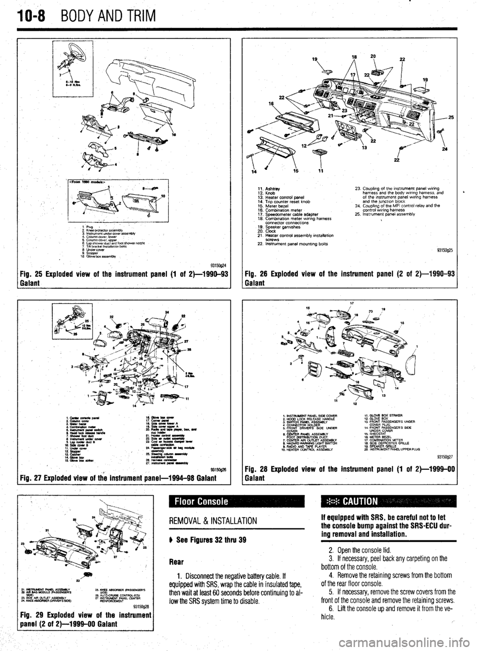
93150@4 Fig. 25 Exploded view of the instrument panel (1 of 2)-1990-93 Fig. 26 Exploded view of the instrument panel (2 of 2)-1990-93
Galant Galant
1.CUllUCU+RC&pllU 16. Gbve bm eewr
i: iiiikz!!T 17. cucw gmnl
4. Cfnnbinuion meta 19. qds cww bww A
5 ‘~fiJzg%L L: ,“zr&, beat. md
21 L% sssemuy
8lmwmemu&cowr 236&1ou(W~
S.LapOdrduQB
10. slds cw4# B 23 ~u,~e-
11. LIdsI corn
::: s%ZZ
14. Gbw bx / ;:+q-=:-
kmasa
IS. Gkw ba SIiikw 2&HWSSCCl!ZL
2rtnsmlmuapr*lrvrnbly
@ma
Fig. 27 Exploded view of the instrument panel-1994-98 Galant
1;. p;;w
13: Heater control panel
14. Trip counter reset knob
15. Meter bezel
16. Combination meter
17. Speedometer cable adapter
18. Combrnatron meter wiring harness
connector connecttons
19. Speaker garnrshes
20. Clock 23. Coupling of the Instrument panel wiring
harness and the body wiring harness, and
of the Instrument panel wrring harness
and the junctlon block
24. Coupling of the MFI control relay and the
control wiring harness
25. Instrument panel assembly
21. Heater control assembly installation
9C?WS 22. Instrument panel mounting bolts
93150925
1. INSTRUMENT PANEL SIDE COVER
2. HOOD LOCK RELEASE HANDLE
3. SWITCH PANEL ASSEMBLY
4 CONNECTOR H+DER
5. ER DRIVERS SIDE UNDER
6. CENTER PANEL ASSEMBLY
FOOT MSTRISUTION DUCT
7. CENTER AIR OUTLET ASSEMBLY
8. HAZARO WARNING LIGHT SWfTCti
9. RADIO AN0 TAPE PLAYER
10. H!ZATER CONTROL ASSEMBLY 1,. GLOV2 BOX STRIKER
12. GLOVE SOX
13 FRONT PASSENGER’S UNOER
COVER PLUG
14. FRONT PASSENGER’S SIDE
UNDER COVER
15. RHEOSTAT
16. METER BEZEL
17. COMBINATION METER
18. SIDE DEFROSTER GRILLE
19 SPEAKER GRILLE
mo. INSTRUMENT PANEL UPPER PLUG
93159927
Fig. 28 Exploded view of the instrument panel (1 of 2)-1999-00
Galant
~~~~~~~~~
Fig. 29 Exploded view of the instrument
REMOVAL &INSTALLATION
) See Figures 32 thru 39 If equipped with SRS, be careful not to let
the console bump against the SRS-ECU dur-
ing removal and installation.
Rear 2. Open the console lid. 3. If necessary, peel back any carpeting on the
bottom of the console.
1. Disconnect the negative battery cable. If
equipped with SRS, wrap the cable in insulated tape,
then wait at least 60 seconds before continuing to al-
low the SRS system time to disable.
4. Remove the retaining screws from the bottom
of the rear floor console.
5. If necessary, remove the screw covers from the
front of the console and remove the retaining screws.
6. Lift the console up and remove it from the ve-
hicle.
rb