ECO mode MITSUBISHI ECLIPSE 1990 Service Manual
[x] Cancel search | Manufacturer: MITSUBISHI, Model Year: 1990, Model line: ECLIPSE, Model: MITSUBISHI ECLIPSE 1990Pages: 391, PDF Size: 15.27 MB
Page 118 of 391
14-6FUEL SYSTEM -Fuel Supply and Fuel Pressure Control
intake manifold/I\
Engine
Fuel
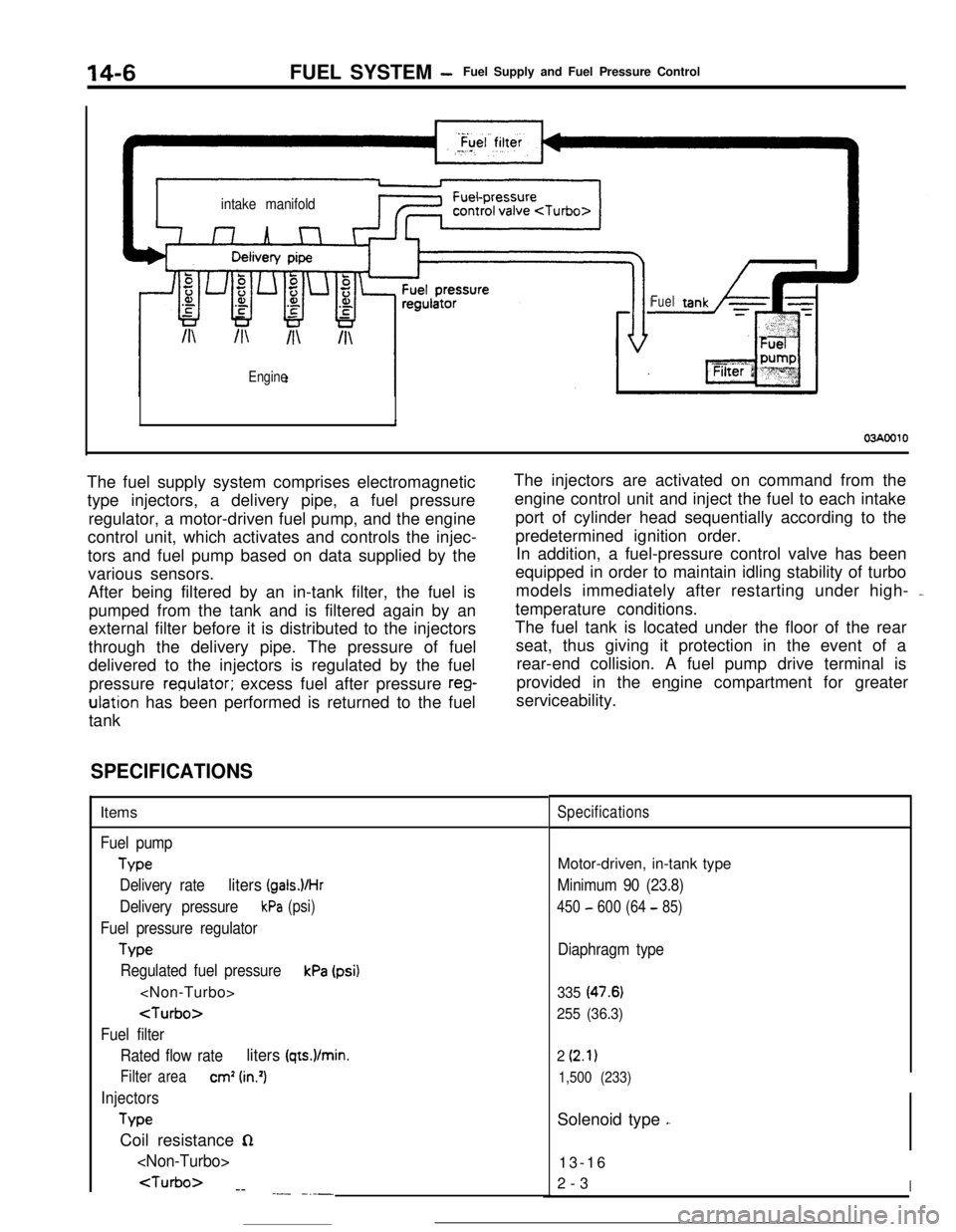
03AOOlOThe fuel supply system comprises electromagnetic
type injectors, a delivery pipe, a fuel pressure
regulator, a motor-driven fuel pump, and the engine
control unit, which activates and controls the injec-
tors and fuel pump based on data supplied by the
various sensors.
After being filtered by an in-tank filter, the fuel is
pumped from the tank and is filtered again by an
external filter before it is distributed to the injectors
through the delivery pipe. The pressure of fuel
delivered to the injectors is regulated by the fuel
pressure
reoulator; excess fuel after pressure reg-ulation has been performed is returned to the fuel
tankThe injectors are activated on command from the
engine control unit and inject the fuel to each intake
port of cylinder head sequentially according to the
predetermined ignition order.
In addition, a fuel-pressure control valve has been
equipped in order to maintain idling stability of turbo
models immediately after restarting under high- -
temperature conditions.
The fuel tank is located under the floor of the rear
seat, thus giving it protection in the event of a
rear-end collision. A fuel pump drive terminal is
provided in the engine compartment for greater
serviceability.
-
SPECIFICATIONSItems
Fuel pump
Type
Delivery rate
liters (gals.VHr
Delivery pressurekPa (psi)
Fuel pressure regulator
Tvw
Regulated fuel pressurekPa (psi)
Fuel filter
Rated flow rate
liters (qts.)/min.
Filter areacm’ (in.‘)
Injectors
TypeCoil resistance
n
--
.- -_-_
SpecificationsMotor-driven, in-tank type
Minimum 90 (23.8)
450 - 600 (64 - 85)
Diaphragm type
335 (47.6)
255 (36.3)
2
(2.1)
1,500 (233)Solenoid type
,.13-16
2-3
I
Page 121 of 391
FUEL SYSTEM -Fuel Supply and Fuel Pressure Control14-9
03Poo4:Diaphragm
from intake
4Fuel from delivery pipe
4m
B(42.7)QQ
2
sl -196 2
(26.4) g
t
$!a d
9
0)Positive5 z‘. pressure
(E.2)
w
FUEL FILTERA high-pressure type filter is installed at the delivery end of the
fuel pump.
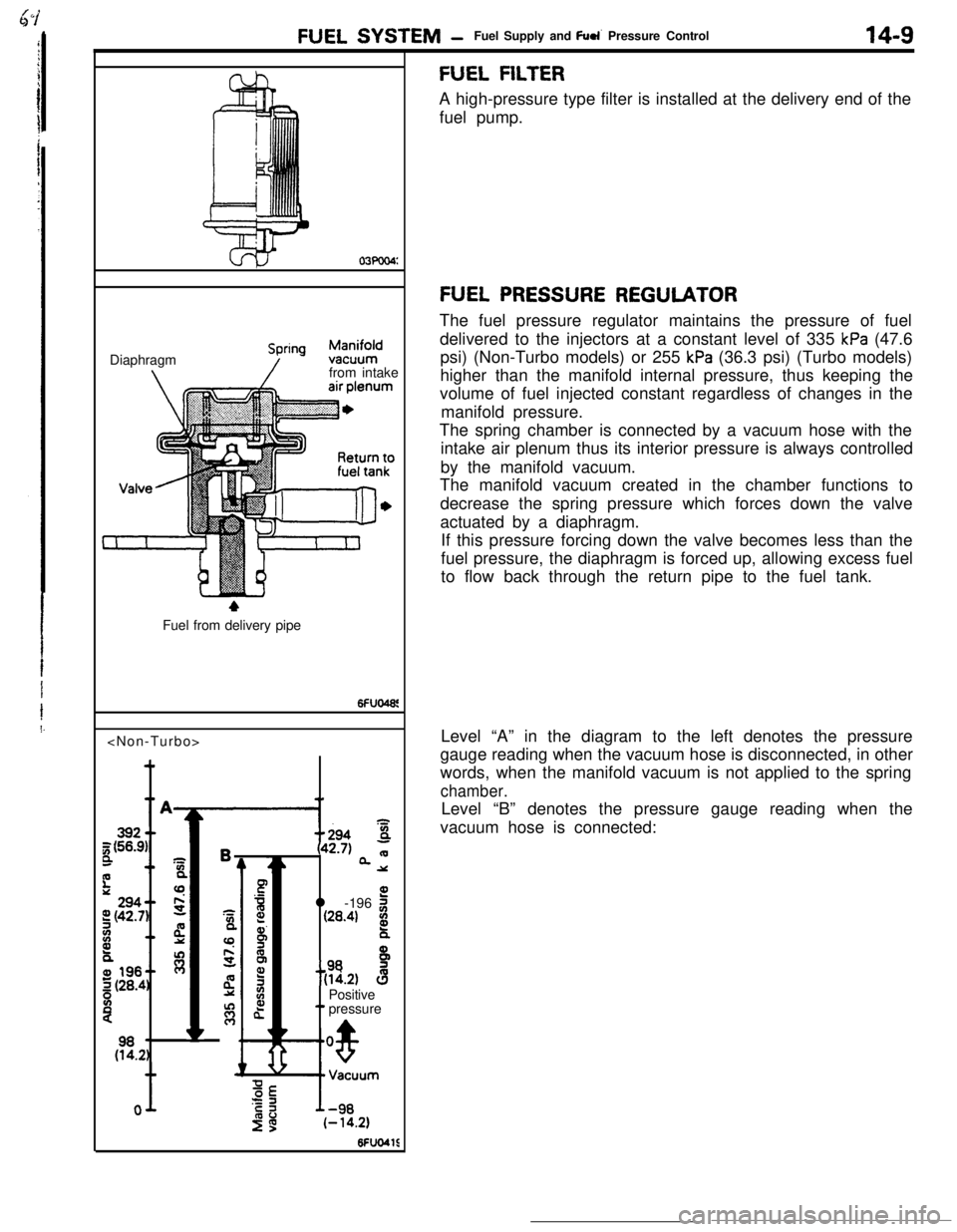
FUEL PRESSURE REGULATORThe fuel pressure regulator maintains the pressure of fuel
delivered to the injectors at a constant level of 335
kPa (47.6
psi) (Non-Turbo models) or 255
kPa (36.3 psi) (Turbo models)
higher than the manifold internal pressure, thus keeping the
volume of fuel injected constant regardless of changes in the
manifold pressure.
The spring chamber is connected by a vacuum hose with the
intake air plenum thus its interior pressure is always controlled
by the manifold vacuum.
The manifold vacuum created in the chamber functions to
decrease the spring pressure which forces down the valve
actuated by a diaphragm.
If this pressure forcing down the valve becomes less than the
fuel pressure, the diaphragm is forced up, allowing excess fuel
to flow back through the return pipe to the fuel tank.
Level “A” in the diagram to the left denotes the pressure
gauge reading when the vacuum hose is disconnected, in other
words, when the manifold vacuum is not applied to the spring
chamber.Level “B” denotes the pressure gauge reading when the
vacuum hose is connected:
Page 126 of 391
14-14
.._~- ---.FUEL SYSTEM
- Sensors
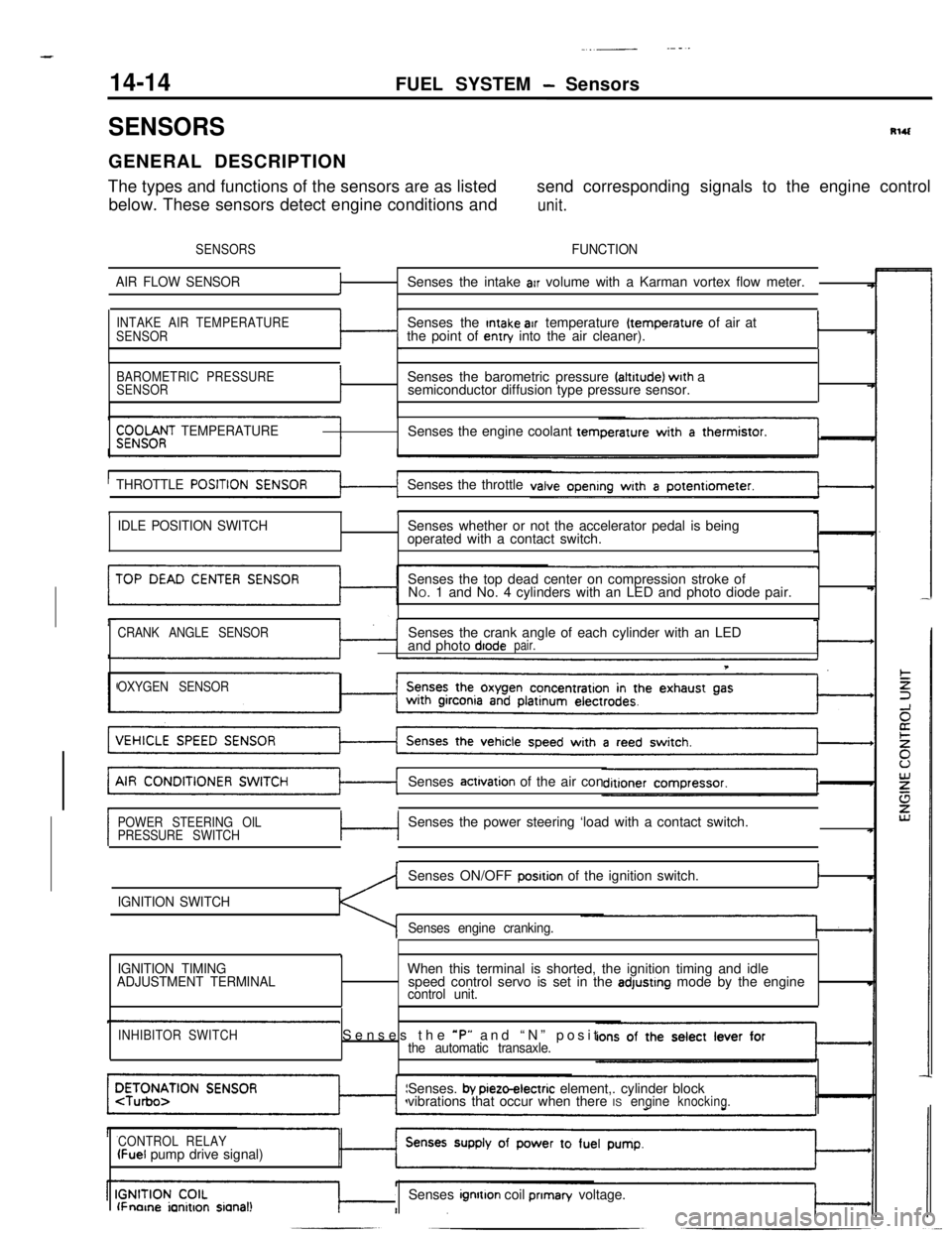
SENSORSRlUGENERAL DESCRIPTION
The types and functions of the sensors are as listedsend corresponding signals to the engine control
below. These sensors detect engine conditions and
unit.
SENSORSFUNCTION
AIR FLOW SENSOR
fSenses the intake arr volume with a Karman vortex flow meter.
INTAKE AIR TEMPERATURE
SENSORSenses the Intake air temperature (temperature of air at
the point of entry into the air cleaner).I
BAROMETRIC PRESSURE
SENSORISenses the barometric pressure faltrtude) wrth a
semiconductor diffusion type pressure sensor.
$;;OOf;T TEMPERATURESenses the engine coolant tern
THROTTLE
POSITISenses the throttle
tI
IDLE POSITION SWITCHSenses whether or not the accelerator pedal is being
operated with a contact switch.
Senses the top dead center on compression stroke of
NO. 1 and No. 4 cylinders with an LED and photo diode pair.
CRANK ANGLE SENSORSenses the crank angle of each cylinder with an LED
and photo diodepair.
T
OXYGEN SENSORSenses
actrvation of the air con
POWER STEERING OIL
PRESSURE SWITCHc-lSenses the power steering ‘load with a contact switch.
IGNITION SWITCHSenses ON/OFF
posrtion of the ignition switch.I
Senses engine cranking.
,
IGNITION TIMING
ADJUSTMENT TERMINALWhen this terminal is shorted, the ignition timing and idle
speed control servo is set in the adjustrng mode by the enginecontrol unit.
INHIBITOR SWITCHSenses the *P” and “N” positthe automatic transaxle.Senses.
by pieto-electric element,. cylinder block
vibrations that occur when there ISengineknocking.
CONTROL RELAY
(Fuel pump drive signal)
lFnorne ianitron sianal!Senses ignrtton coil prIman/ voltage.
Page 144 of 391
__.-~-..- -
FUEL SYSTEM- Ermine Control Unit
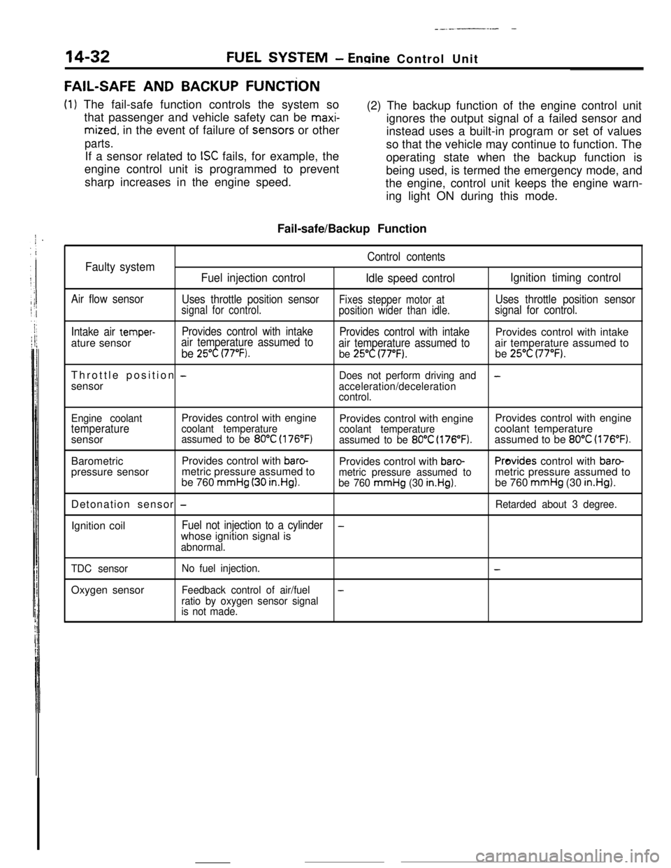
FAIL-SAFE AND BACKUP FUNCTiON
(1) The fail-safe function controls the system so
that passenger and vehicle safety can be
maxi-
mized. in the event of failure of sens.ors or other
parts.If a sensor related to
ISC fails, for example, the
engine control unit is programmed to prevent
sharp increases in the engine speed.(2) The backup function of the engine control unit
ignores the output signal of a failed sensor and
instead uses a built-in program or set of values
so that the vehicle may continue to function. The
operating state when the backup function is
being used, is termed the emergency mode, and
the engine, control unit keeps the engine warn-
ing light ON during this mode.
Fail-safe/Backup Function
Control contentsFaulty system
Fuel injection control
Idle speed controlIgnition timing control
Air flow sensor
Uses throttle position sensorFixes stepper motor atUses throttle position sensorsignal for control.
position wider than idle.signal for control.
Intake air
temper-Provides control with intake
Provides control with intakeProvides control with intake
ature sensorair temperature assumed to
be 25°C (77°F).air temperature assumed toair temperature assumed tobe 25°C (77°F).be 25°C (77°F).Throttle position
-Does not perform driving and-sensor
acceleration/deceleration
control.
Engine coolantProvides control with engine
Provides control with engineProvides control with engine
temperaturecoolant temperature
coolant temperaturecoolant temperature
sensorassumed to be 80°C (176°F)assumed to be 80°C (176°F).assumed to be 80°C (176°F).BarometricProvides control with
baro-Provides control with baro-Provides control with baro-pressure sensormetric pressure assumed to
be 760
mmHg (30 in.HgI.metric pressure assumed tometric pressure assumed tobe 760 mmHg (30 in.Hg).be 760 mmHg (30 in.Hg).Detonation sensor
-Retarded about 3 degree.Ignition coil
Fuel not injection to a cylinder-whose ignition signal is
abnormal.
TDC sensorOxygen sensor
No fuel injection.-
Feedback control of air/fuel-
ratio by oxygen sensor signal
is not made.
Page 146 of 391
-
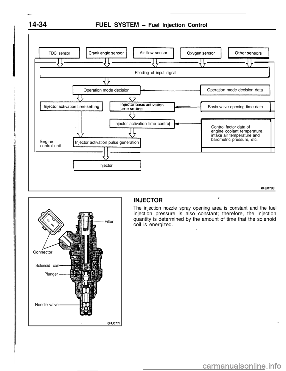
14-34FUEL SYSTEM - Fuel Injection Control
TDC sensorAir flow sensor
I
Reading of input signal1
I ,,
uOperation mode decisionOperation mode decision data
I rBasic valve opening time data
Enginecontrol unitInjector activation time control
Injector activation pulse generationControl factor data of
engine coolant temperature,
intake air temperature and
barometric pressure, etc.
Injector1
6FUO766Needle valveFilter
Connector
Solenoid coil
Plunger
-4
INJECTOR,
The injection nozzle spray opening area is constant and the fuelinjection pressure is also constant; therefore, the injection
quantity is determined by the amount of time that the solenoid
coil is energized.
.
Page 148 of 391
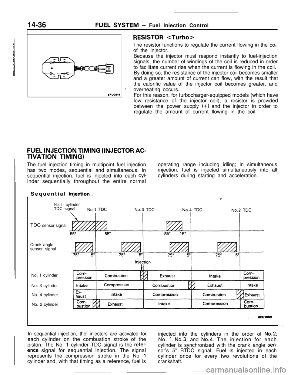
14-36FUEL SYSTEM- Fuel lniection Control
SFUOSlS
RESISTOR
co,.of the injector.
Because the injector must respond instantly to fuel-injection
signals, the number of windings of the coil is reduced in order
to facilitate current rise when the current is flowing in the coil.
By doing so, the resistance of the injector coil becomes smaller
and a greater amount of current can flow, with the result that
the calorific value of the injector coil becomes greater, and
1overheating occurs.
For this reason, for turbocharger-equipped models (which have
low resistance of the injector coil), a resistor is provided
between the power supply (+) and the injector in order to
regulate the amount of current flowing in the coil.
FUEL INJECTION TIMING (INJECTOR AC-
TIVATION TIMING)
The fuel injection timing in multipoint fuel injection
has two modes, sequential and simultaneous. In
sequential injection, fuel is injected into each
cyl-inder sequentially throughout the entire normaloperating range including idling; in simultaneous
injection, fuel is injected simultaneously into all
cylinders during starting and acceleration.
Sequential Injection
r
No. 1cylinder
TDC sensor signal
Crank angle
sensor signal
No. 1 cylinder
No. 3 cylinder
No. 4 cylinder
No. 2 cylinder
In sequential injection, the’ injectors are activated foreach cylinder on the combustion stroke of the
piston. The No. 1 cylinder TDC signal is the
refer-
ence signal for sequential injection. The signal
represents the compression stroke in the No.
1cylinder and, with that timing as a reference, fuel isinjected into the cylinders in the order of
No.2,No.
1, No.3, and No.4. The injection for each
cylinder is synchronized with the crank angle
sen-sor’s 5” BTDC signal. Fuel is injected in each
cylinder once for every two revolutions of the
crankshaft.
-
Page 167 of 391
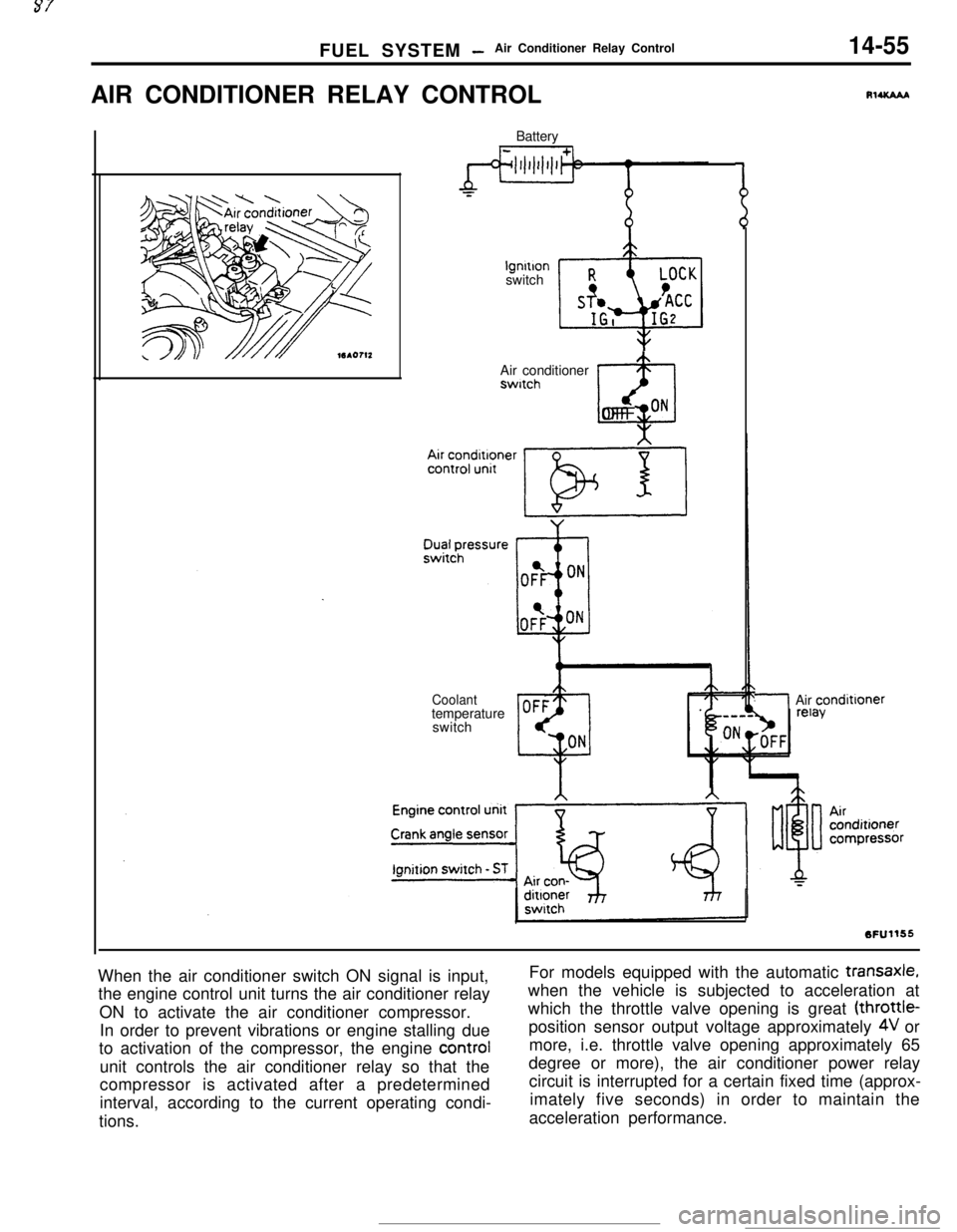
FUEL SYSTEM -Air Conditioner Relay Control14-55AIR CONDITIONER RELAY CONTROL
Batterylgnltlon
switch
Air conditionerswitch
@OFF ON
Coolanttemperature
switch
RlUCAAA
/Air condittoner
When the air conditioner switch ON signal is input,
the engine control unit turns the air conditioner relay
ON to activate the air conditioner compressor.
In order to prevent vibrations or engine stalling due
to activation of the compressor, the engine control
unit controls the air conditioner relay so that the
compressor is activated after a predetermined
interval, according to the current operating condi-
tions.For models equipped with the automatic
transaxle,when the vehicle is subjected to acceleration at
which the throttle valve opening is great (throttle-
position sensor output voltage approximately
4V or
more, i.e. throttle valve opening approximately 65
degree or more), the air conditioner power relay
circuit is interrupted for a certain fixed time (approx-
imately five seconds) in order to maintain the
acceleration performance.
Page 176 of 391
![MITSUBISHI ECLIPSE 1990 Service Manual 14-64FUEL SYSTEM - Auto-cruise Control System
FixedAccelera-FixedSpeed -c tion-LC speed
High
Vehic’e iapprox. 40 km/hspeedG!5 mph) or hagher]Low
’When the RESUME
(ACCEL) Switch is Kept Turned
Whi MITSUBISHI ECLIPSE 1990 Service Manual 14-64FUEL SYSTEM - Auto-cruise Control System
FixedAccelera-FixedSpeed -c tion-LC speed
High
Vehic’e iapprox. 40 km/hspeedG!5 mph) or hagher]Low
’When the RESUME
(ACCEL) Switch is Kept Turned
Whi](/img/19/57103/w960_57103-175.png)
14-64FUEL SYSTEM - Auto-cruise Control System
FixedAccelera-FixedSpeed -c tion-LC speed
High
Vehic’e iapprox. 40 km/hspeedG!5 mph) or hagher]Low
’When the RESUME
(ACCEL) Switch is Kept Turned
While the RESUME switch is ON, the actuator’s DC
mote,caused to rotate to the PULL side; the vehicle speed when the
switch is switched OFF as acceleration continues is entered in
the memory, and is thereafter controlled as the fixed speed.
CANCELLATION
When, during fixed-speed driving, the signals described below
are input, conductivity to the electromagnetic clutch is inter-
rupted, thus
cancelling the auto-cruise control system.
l Stop light switch ON (brake pedal depressed)
l Clutch switch ON (clutch pedal depressed)
lInhibitor switch ON (selector lever at
“P” or “N” position)
LOW-SPEED LIMIT
There is automatic cancellation at or below the low-speed limit
vehicle speed [approximately 40 km/h (25 mph)].
HIGH-SPEED LIMIT
The vehicle cannot be driven at a fixed speed which is at or
higher than the high-speed limit [approximately 145 km/h
(90
mph)l.Note that the vehicle speed memorized when the SET switch
a5pressed while the vehicle is traveling at the high-speed limit or
higher
vvill be the high-speed limit vehicle speed.
FAIL-SAFE FUNCTION
When the following situations are encountered during fixed-
speed driving, the signals to interrupt, conductivity to the
electromagnetic clutch are input, thus canceling the auto-cruise
control system.
0
0
0When vehicle speed decreases to the low-speed limit
[approx. 40 km/h (25 mph)].
If the vehicle speed decreases to a speed which is
approximately 20 km/h (12 mph) or more below ‘the
memorized vehicle speed.
When the vehicle speed drops by 20 km/h
(12 mph) or more
after having reached the set speed -10 km/h (-6 mph) in
the RESUME mode.
If there is damaged or disconnected wiring of the input line
(stop light switch load side) of the stop light switch.
if there is no input of the vehicle speed signal for a certain
fixed time (1 second or longer).
If the SET and RESUME control switches are switched ON
at the same time.
If the cancel switches (stop light switch, clutch switch or
inhibitor switch) and command switches (SET switch
orRESUME switch) are switched ON at the same time.
if the actuator clutch driver (transistor) of the control unk
remains ON (short-circuit).
Page 177 of 391
Page 186 of 391
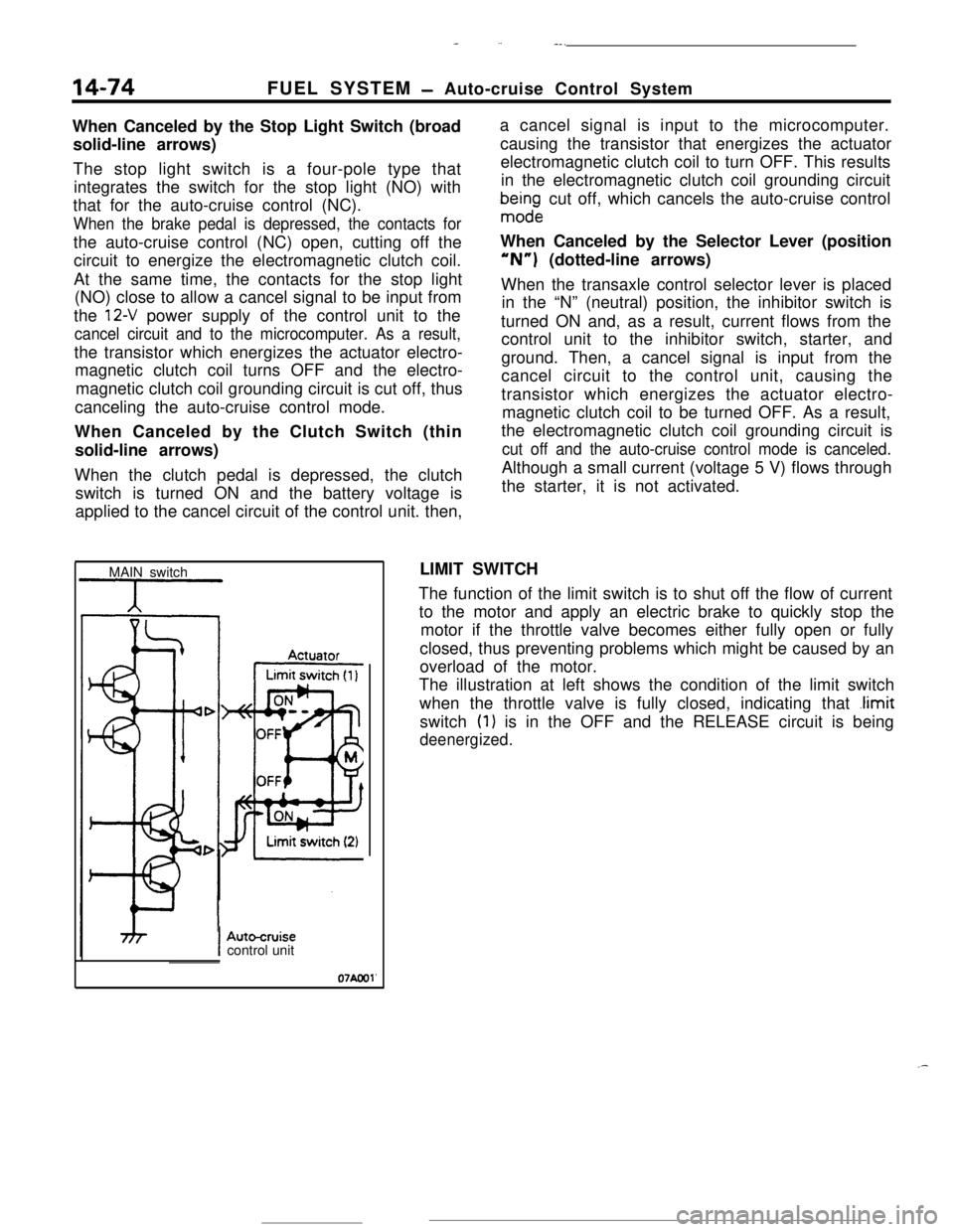
14-74
_ ,.-..FUEL SYSTEM
- Auto-cruise Control System
When Canceled by the Stop Light Switch (broad
solid-line arrows)
The stop light switch is a four-pole type that
integrates the switch for the stop light (NO) with
that for the auto-cruise control (NC).
When the brake pedal is depressed, the contacts forthe auto-cruise control (NC) open, cutting off the
circuit to energize the electromagnetic clutch coil.
At the same time, the contacts for the stop light
(NO) close to allow a cancel signal to be input from
the
12-V power supply of the control unit to the
cancel circuit and to the microcomputer. As a result,the transistor which energizes the actuator electro-
magnetic clutch coil turns OFF and the electro-
magnetic clutch coil grounding circuit is cut off, thus
canceling the auto-cruise control mode.
When Canceled by the Clutch Switch (thin
solid-line arrows)
When the clutch pedal is depressed, the clutch
switch is turned ON and the battery voltage is
applied to the cancel circuit of the control unit. then,a cancel signal is input to the microcomputer.
causing the transistor that energizes the actuator
electromagnetic clutch coil to turn OFF. This results
in the electromagnetic clutch coil grounding circuit
bma$ndge cut off, which cancels the auto-cruise control
When Canceled by the Selector Lever (position“N”) (dotted-line arrows)
When the transaxle control selector lever is placed
in the “N” (neutral) position, the inhibitor switch is
turned ON and, as a result, current flows from the
control unit to the inhibitor switch, starter, and
ground. Then, a cancel signal is input from the
cancel circuit to the control unit, causing the
transistor which energizes the actuator electro-
magnetic clutch coil to be turned OFF. As a result,
the electromagnetic clutch coil grounding circuit is
cut off and the auto-cruise control mode is canceled.Although a small current (voltage 5 V) flows through
the starter, it is not activated.
MAIN switchLIMIT SWITCH
The function of the limit switch is to shut off the flow of current
to the motor and apply an electric brake to quickly stop the
motor if the throttle valve becomes either fully open or fully
closed, thus preventing problems which might be caused by an
overload of the motor.
The illustration at left shows the condition of the limit switch
when the throttle valve is fully closed, indicating that
.limitswitch
(1) is in the OFF and the RELEASE circuit is being
deenergized.
IAutocruisecontrol unit
07Aool'
.-