battery MITSUBISHI ECLIPSE 1990 User Guide
[x] Cancel search | Manufacturer: MITSUBISHI, Model Year: 1990, Model line: ECLIPSE, Model: MITSUBISHI ECLIPSE 1990Pages: 391, PDF Size: 15.27 MB
Page 143 of 391
FUEL SYSTEM - Engine Control Unit14-31
r
L
IMPI
Ground
1 Engine control unit
Engine wam-
$b?Stionindicator
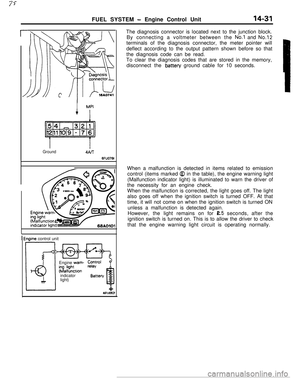
light)The diagnosis connector is located next to the junction block.
By connecting a voltmeter between the
No.1 and No.12terminals of the diagnosis connector, the meter pointer will
deflect according to the output pattern shown before so that
the diagnosis code can be read.
To clear the diagnosis codes that are stored in the memory,
disconnect the
.battery ground cable for 10 seconds.
When a malfunction is detected in items related to emission
control (items marked
Q in the table), the engine warning light
(Malfunction indicator light) is illuminated to warn the driver of
the necessity for an engine check.
When the malfunction is corrected, the light goes off. The light
also goes off when the ignition switch is turned OFF. At that
time, it will not come on when the ignition switch is turned ON
unless a malfunction is detected again.
However, the light remains on for
E.5 seconds, after the
ignition switch is turned on. This is to allow the driver to check
that the engine warning light circuit is operating normally.
Page 147 of 391

FUEL SYSTEM- Fuel Injection Control14-35INJECTOR CIRCUIT
,Battew
Control relay
Resistor
No.Injector
Engine control unit
6FU0516Electricity from the battery flows to the control relay
and then to the resistor (turbocharger-equipped
models only), the injector, and the engine control
unit.Upon reception of the fuel injection signal, theengine control unit causes the power transistor to
be turned ON, thus completing the injector ground
circuit. In this situation, current flows to the injector,
which injects fuel while the power transistor is ON.
Page 154 of 391
14-42
FUEL SYSTEM- Fuel Injection Control
4
Fz.or.c
4:0/
E
{!*760 (301Barometric pressure
mmHg (in.Hg) 6Fuo9z
c
Timet
6FUO279Drivecurrent
0: bri
F2JJ’ ipe; II
I+-JValve opening timi16240:
E‘C
F
.-
is
3
3:\Battery voltage
V162406
80 (176)Coolant temperature
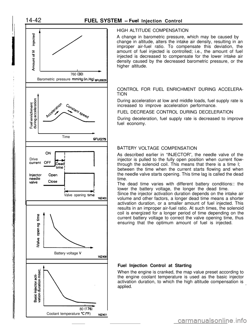
“C (“F)162401HIGH ALTITUDE COMPENSATION
A change in barometric pressure, which may be caused by
change in altitude, alters the intake air density, resulting in an
improper air-fuel ratio. To compensate this deviation, the
amount of fuel injected is controlled; i.e., the amount of fuel
injected is decreased to compensate for the lower intake air
density caused by the decreased barometric pressure, or the
higher altitude.
CONTROL FOR FUEL ENRICHMENT DURING ACCELERA-
TIONDuring acceleration at low and middle loads, fuel supply rate is
increased to improve acceleration performance.
FUEL DECREASE CONTROL DURING DECELERATION
During deceleration, fuel supply rate is decreased to improve
fuel economy.
BATTERY VOLTAGE COMPENSATION
As described earlier in “INJECTOR”, the needle valve of the
injector is pulled to the fully open position when current flow-
through the solenoid coil. This means that there is a time I;
between the time when the current starts flowing and when
the needle valve starts opening. This time lag is called the dead
time.
The dead time varies with different battery conditions:: the
lower the battery voltage, the longer the dead time.
Since the injector activation duration depends on the intake air
volume and other factors, a longer dead time means a shorter
activation duration, or a smaller amount of fuel injected. This
results in an improper air-fuel ratio. At such times, the solenoid
coil is energized for a longer period of time depending on the
current battery voltage to correct the valve opening time, thus
ensuring that the optimum amount of fuel is injected.
Fuel Injection Control at Starting
When the engine is cranked, the map value preset according to
the engine coolant temperature is used as the basic injector
activation duration, to which the high altitude compensation is
applied..
Page 158 of 391
.
14-46FUEL SYSTEM- Idle Speed Control
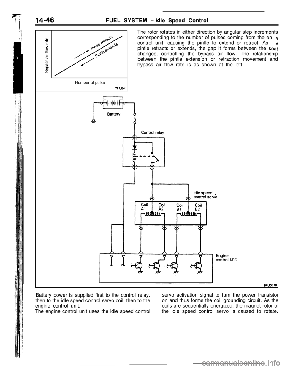
The rotor rotates in either direction by angular step increments
corresponding to the number of pulses coming from the en
?control unit, causing the pintle to extend or retract. As
pintle retracts or extends, the gap it forms between the
sea:changes, controlling the bypass air flow. The relationship
between the pintle extension or retraction movement and
bypass air flow rate is as shown at the left.
Number of pulse
7F UW(Control relay
@iI---
unit
Battery power is supplied first to the control relay,
then to the idle speed control servo coil, then to theservo activation signal to turn the power transistor
engine control unit.on and thus forms the coil grounding circuit. As the
The engine control unit uses the idle speed controlcoils are sequentially energized, the magnet rotor of
the idle speed control servo is caused to rotate.
Page 166 of 391
FUEL SYSTEM- Power Supply Control
Battery
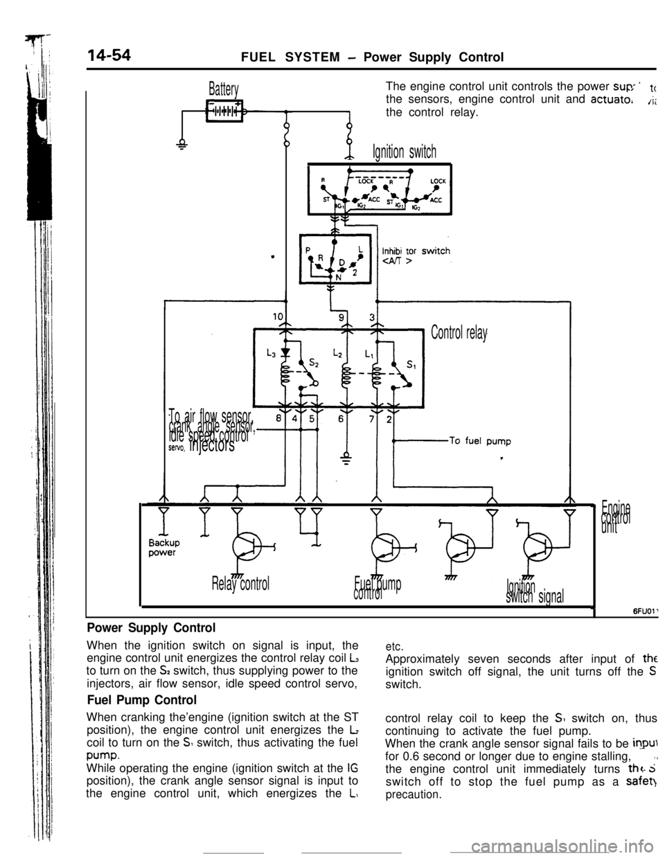
L11The engine control unit controls the power
suv ’tcthe sensors, engine control unit and
actuate,A;the control relay.
-P
.
-p.Ignition switch
Inn yr
To air flow sensor,crank angle sensor,idle speed controlsetvo. injectors
Control relay
Relay controlFuel pump
controlIgnitionswitch signal
Enginecontrol
unit
I6FUOl’
Power Supply ControlWhen the ignition switch on signal is input, the
engine control unit energizes the control relay coil
L3to turn on the
S2 switch, thus supplying power to the
injectors, air flow sensor, idle speed control servo,
Fuel Pump ControlWhen cranking the’engine (ignition switch at the ST
position), the engine control unit energizes the
Lcoil to turn on the
S switch, thus activating the fuel
pump.While operating the engine (ignition switch at the
IGposition), the crank angle sensor signal is input to
the engine control unit, which energizes the
L,
etc.Approximately seven seconds after input of
theignition switch off signal, the unit turns off the
Sswitch.
control relay coil to keep the
SI switch on, thus
continuing to activate the fuel pump.
When the crank angle sensor signal fails to be
inputfor 0.6 second or longer due to engine stalling,
.,the engine control unit immediately turns
thz. 5switch off to stop the fuel pump as a safet)
precaution.
Page 167 of 391
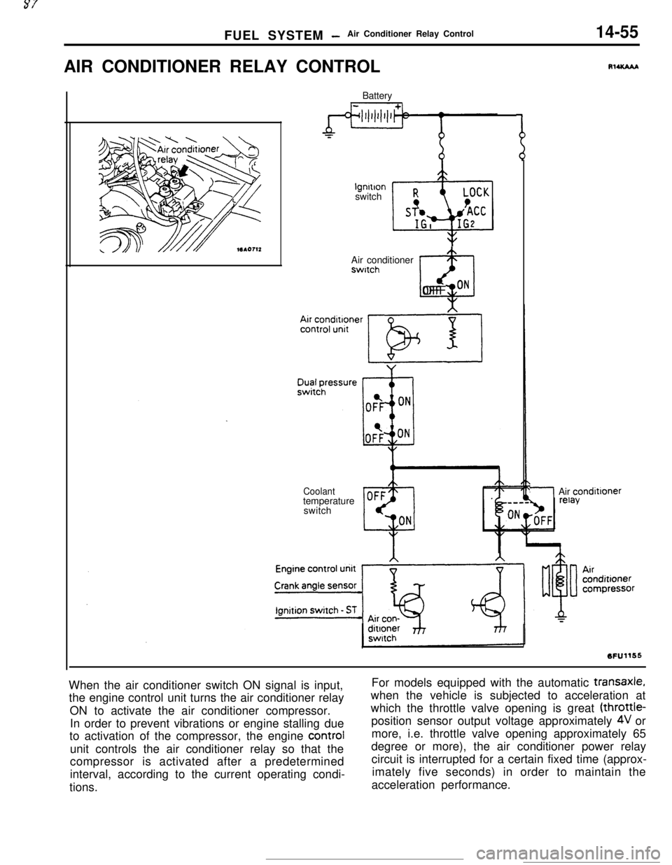
FUEL SYSTEM -Air Conditioner Relay Control14-55AIR CONDITIONER RELAY CONTROL
Batterylgnltlon
switch
Air conditionerswitch
@OFF ON
Coolanttemperature
switch
RlUCAAA
/Air condittoner
When the air conditioner switch ON signal is input,
the engine control unit turns the air conditioner relay
ON to activate the air conditioner compressor.
In order to prevent vibrations or engine stalling due
to activation of the compressor, the engine control
unit controls the air conditioner relay so that the
compressor is activated after a predetermined
interval, according to the current operating condi-
tions.For models equipped with the automatic
transaxle,when the vehicle is subjected to acceleration at
which the throttle valve opening is great (throttle-
position sensor output voltage approximately
4V or
more, i.e. throttle valve opening approximately 65
degree or more), the air conditioner power relay
circuit is interrupted for a certain fixed time (approx-
imately five seconds) in order to maintain the
acceleration performance.
Page 185 of 391
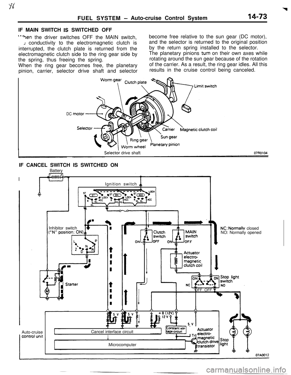
FUEL SYSTEM -Auto-cruise Control System14-73IF MAIN SWITCH
IS SWITCHED OFF
‘*‘hen the driver switches OFF the MAIN switch,
Jconductivity to the electromagnetic clutch is
interrupted, the clutch plate is returned from the
electromagnetic clutch side to the ring gear side by
the spring, thus freeing the spring.
When the ring gear becomes free, the planetary
pinion, carrier, selector drive shaft and selectorbecome free relative to the sun gear (DC motor),
and the selector is returned to the original position
by the return spring installed to the selector.
The planetary pinions
turn on their own axes while
rotating around the sun gear because of the rotation
of the carrier. As a result, the ring gear idles. All this
results in the cruise control being canceled.
DCSelector drive shaft
IF CANCEL SWITCH IS SWITCHED ON
IBattery
IIIIgnition switch 411IInhibitor switch
f’ J
r--
if-Starterz _Auto-cruise
f
AA)\AA
5V
pF p
+ i%zv)
5-VComl
Cancel interface circuit
bs- Tts ec
I
r-
[ON
NC: Normally closed
NO: Normally opened
‘OFF OFF
IMicrocomputer
Page 186 of 391
14-74
_ ,.-..FUEL SYSTEM
- Auto-cruise Control System
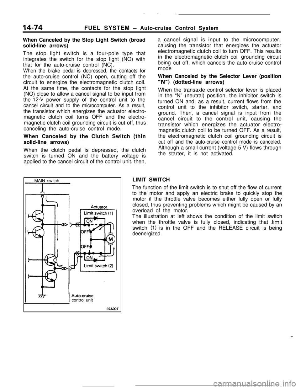
When Canceled by the Stop Light Switch (broad
solid-line arrows)
The stop light switch is a four-pole type that
integrates the switch for the stop light (NO) with
that for the auto-cruise control (NC).
When the brake pedal is depressed, the contacts forthe auto-cruise control (NC) open, cutting off the
circuit to energize the electromagnetic clutch coil.
At the same time, the contacts for the stop light
(NO) close to allow a cancel signal to be input from
the
12-V power supply of the control unit to the
cancel circuit and to the microcomputer. As a result,the transistor which energizes the actuator electro-
magnetic clutch coil turns OFF and the electro-
magnetic clutch coil grounding circuit is cut off, thus
canceling the auto-cruise control mode.
When Canceled by the Clutch Switch (thin
solid-line arrows)
When the clutch pedal is depressed, the clutch
switch is turned ON and the battery voltage is
applied to the cancel circuit of the control unit. then,a cancel signal is input to the microcomputer.
causing the transistor that energizes the actuator
electromagnetic clutch coil to turn OFF. This results
in the electromagnetic clutch coil grounding circuit
bma$ndge cut off, which cancels the auto-cruise control
When Canceled by the Selector Lever (position“N”) (dotted-line arrows)
When the transaxle control selector lever is placed
in the “N” (neutral) position, the inhibitor switch is
turned ON and, as a result, current flows from the
control unit to the inhibitor switch, starter, and
ground. Then, a cancel signal is input from the
cancel circuit to the control unit, causing the
transistor which energizes the actuator electro-
magnetic clutch coil to be turned OFF. As a result,
the electromagnetic clutch coil grounding circuit is
cut off and the auto-cruise control mode is canceled.Although a small current (voltage 5 V) flows through
the starter, it is not activated.
MAIN switchLIMIT SWITCH
The function of the limit switch is to shut off the flow of current
to the motor and apply an electric brake to quickly stop the
motor if the throttle valve becomes either fully open or fully
closed, thus preventing problems which might be caused by an
overload of the motor.
The illustration at left shows the condition of the limit switch
when the throttle valve is fully closed, indicating that
.limitswitch
(1) is in the OFF and the RELEASE circuit is being
deenergized.
IAutocruisecontrol unit
07Aool'
.-
Page 188 of 391
- -----.--..
14-76FUEL SYSTEM -Auto-cruise Control System
Ignition switch
IGI
9
RESUActuator electro-
Microcomputer
1 T 1
rn’Auto-cruise control unit
Autocruisecontrol switch
IGlMAIN
;FF -+++&Control unit
power supply
terminal voltage
03AO264NC: Normally closed
07*0040
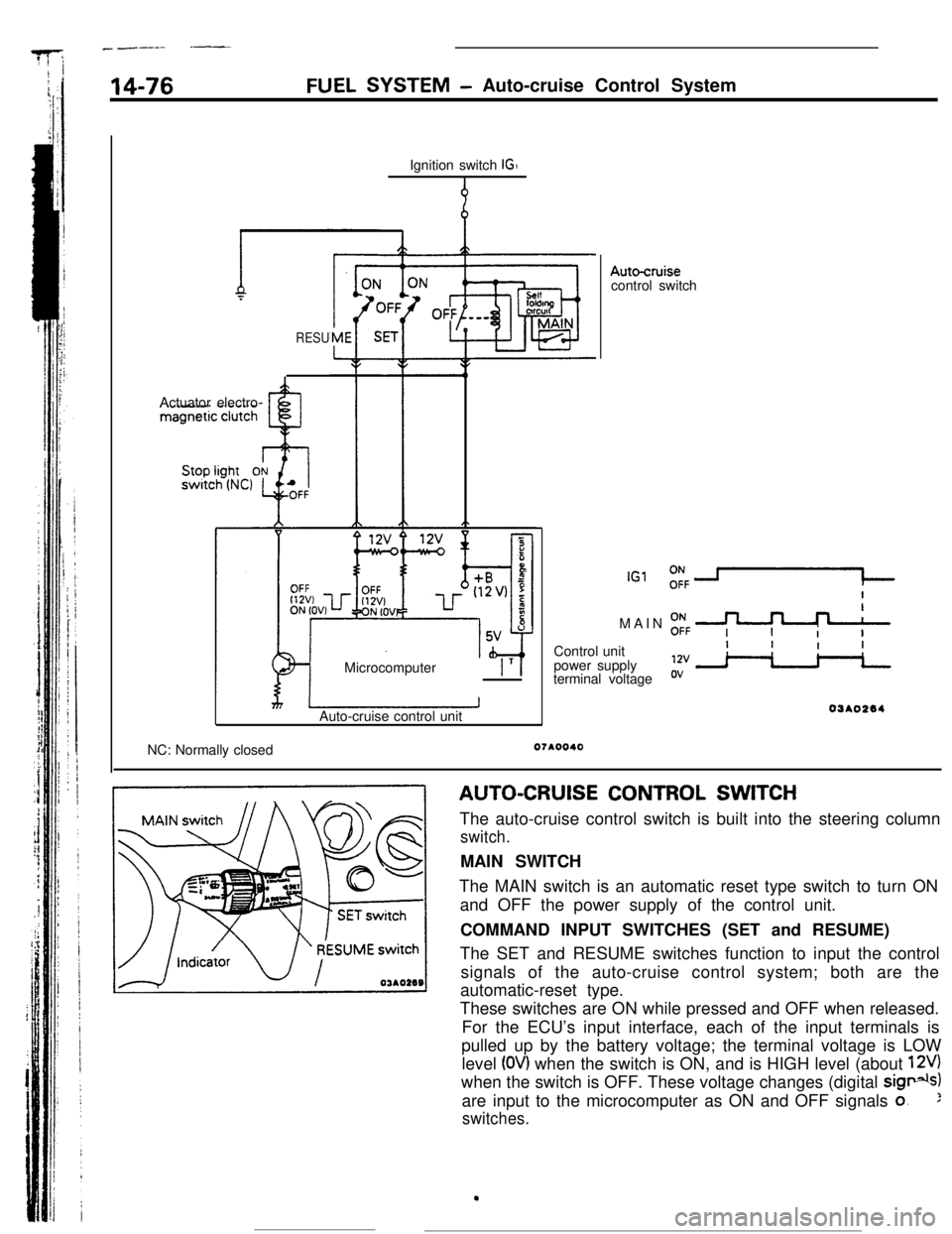
AUTO-CRUISE CONTROL SWITCH
The auto-cruise control switch is built into the steering column
switch.MAIN SWITCH
The MAIN switch is an automatic reset type switch to turn ON
and OFF the power supply of the control unit.
COMMAND INPUT SWITCHES (SET and RESUME)
The SET and RESUME switches function to input the control
signals of the auto-cruise control system; both are the
automatic-reset type.
These switches are ON while pressed and OFF when released.
For the ECU’s input interface, each of the input terminals is
pulled up by the battery voltage; the terminal voltage is LOW
level
(OV) when the switch is ON, and is HIGH level (about 12V)when the switch is OFF. These voltage changes (digital
sig*)are input to the microcomputer as ON and OFF signals
o.:
switches.
.
Page 276 of 391
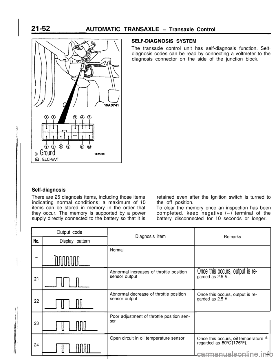
AUTOMATIC TRANSAXLE - Transaxle ControlSELF-DIAGNOStS SYSTEM
The transaxle control unit has self-diagnosis function.
Self-diagnosis codes can be read by connecting a voltmeter to the
diagnosis connector on the side of the junction block.
0: Ground
6%: ELC-MIT
Self-diagnosisThere are 25 diagnosis items, including those items
indicating normal conditions; a maximum of
10items can be stored in memory in the order that
they occur. The memory is supported by a power
supply directly connected to the battery so that it isretained even after the Ignition switch is turned to
the off position.
To clear the memory once an inspection has been
completed. keep negative
(-) terminal of the
battery disconnected for
10 seconds or longer.
r
No.
23
24
Output code
Display pattern
TDiagnosis itemRemarks
NormalAbnormal increases of throttle position
sensor output
Abnormal decrease of throttle position
sensor output
Poor adjustment of throttle position sen-
sorOpen circuit in oil temperature sensor
Once this occurs, output is re-
garded as 2.5 V.Once this occurs, output is re-
garded as 2.5 VOnce this occurs,
oil temperature isregarded as 80°C (176°F).