battery MITSUBISHI ECLIPSE 1990 Owner's Manual
[x] Cancel search | Manufacturer: MITSUBISHI, Model Year: 1990, Model line: ECLIPSE, Model: MITSUBISHI ECLIPSE 1990Pages: 391, PDF Size: 15.27 MB
Page 338 of 391
BODY - Central Door Locks23-21
IBattery
1IJDoor lock 4Door lockactuator t(left side)actuator
(right side) -Battery
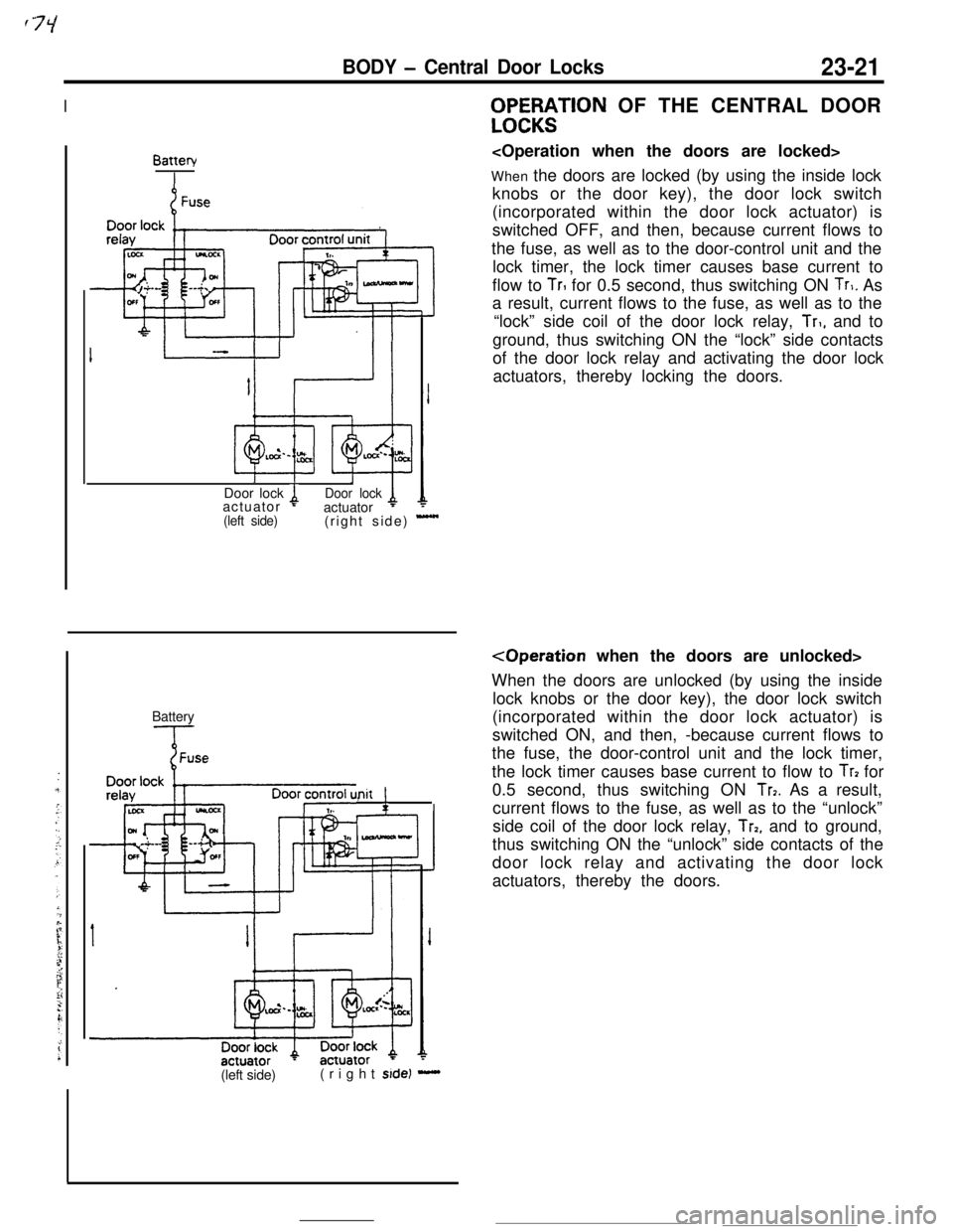
Init !,WF%;$TlON OF THE CENTRAL DOOR
When the doors are locked (by using the inside lock
knobs or the door key), the door lock switch
(incorporated within the door lock actuator) is
switched OFF, and then, because current flows to
the fuse, as well as to the door-control unit and the
lock timer, the lock timer causes base current to
flow to
TrI for 0.5 second, thus switching ON Tr,. As
a result, current flows to the fuse, as well as to the
“lock” side coil of the door lock relay,
Tr,, and to
ground, thus switching ON the “lock” side contacts
of the door lock relay and activating the door lock
actuators, thereby locking the doors.
When the doors are unlocked (by using the inside
lock knobs or the door key), the door lock switch
(incorporated within the door lock actuator) is
switched ON, and then, -because current flows to
the fuse, the door-control unit and the lock timer,
the lock timer causes base current to flow to
Tr? for
0.5 second, thus switching ON
Tr7. As a result,
current flows to the fuse, as well as to the “unlock”
side coil of the door lock relay,
Trp, and to ground,
thus switching ON the “unlock” side contacts of the
door lock relay and activating the door lock
actuators, thereby the doors.
(left side)(right
side) -
Page 339 of 391
23-22BODY - Power Windows
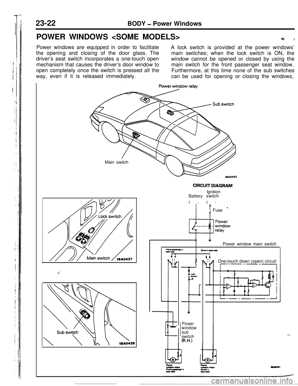
POWER WINDOWS
R’1Power windows are equipped in order to facilitate
A lock switch is provided at the power windows’
the opening and closing of the door glass. The
main switches; when the lock switch is ON, the
driver’s seat switch incorporates a one-touch open
mechanism that causes the driver’s door window towindow cannot be opened or closed by using the
main switch for the front passenger seat window.
open completely once the switch is pressed all the
way, even if it is released immediately.Furthermore, at this time none of the sub switches
can be used for opening or closing the windows,
Main switch
CIRCUIT DIAGRAMIgnition
Battery switch
l-l-
’ 1Fuse ’
Z*,“““”CrPower window main switch
-*W(WlI. _;:
r-
L
--e.
.
I
ELnA
I
Powerwindow
subswitch
(R.H.)
I IOne-touch down (open) circuit
--P’-‘-,
-
Page 340 of 391
BODY - Power Windows23-23
IBatterv
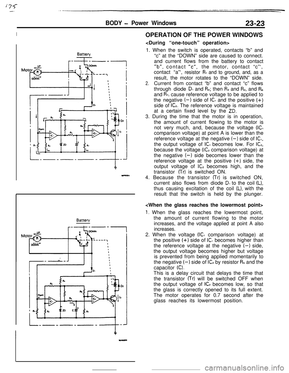
---IBatteryOPERATION OF THE POWER WINDOWS
1. When the switch is operated, contacts “b” and
“c” at the “DOWN” side are caused to connect.
and current flows from the battery to contact
“b”, contact “c”,the motor, contact “c”‘,
contact “a”‘,
resistor R and to ground, and, as aresult, the motor rotates to the “DOWN” side.
2.Current from contact “b” and contact “c” flows
through diode
DI and R.; then I% and I%, and R,and
R7, cause reference voltage to be applied to
the negative
(-) side of IC and the positive (+)
side of
G. The reference voltage is maintained
at a certain fixed level by the
ZD.3. During the time that the motor is in operation,
the amount of current flowing to the motor is
not very much, and, because the voltage
(ICcomparison voltage) at point A is lower than the
reference voltage at the negative
(-) side of IC,,the output voltage of
IC becomes low. For G,because the voltage
(G comparison voltage) at
the negative
(-) side becomes lower than the
reference voltage at the positive (+) side, the
output voltage of
lC2 becomes high, and the
transistor
(Tr) is switched ON.
4. Because the transistor
(Tr) is switched ON,
current also flows from diode
D1 to the coil (L).thus causing excitation of the coil
IL), with the
result that the switch is held by the plunger.
1. When the glass reaches the lowermost point,
the amount of current flowing to the motor
increases, and the voltage applied at point A also
increases.2. When the voltage
(IC comparison voltage) at
the positive
(+) side of IC becomes higher than
the reference voltage at the negative
(-) side,
the output voltage becomes higher but voltage
is prevented from being applied momentarily to
the negative
I-) side of ICI by resistor R6 and the
capacitor
0.This is a delay circuit that delays the time that
the transistor
(Tr) will be switched OFF when
the output voltage of
IC, becomes low, so that
the glass is correctly opened to its full extent.
The motor operates for 0.7 second after the
glass reaches its lowermost position.
Page 355 of 391
23-38BODY - Seat Belts
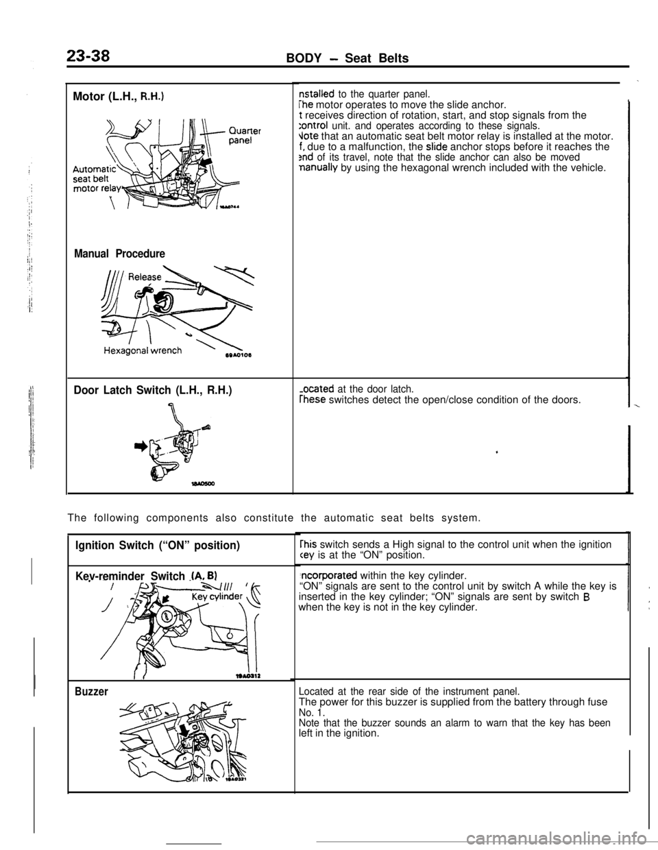
Motor (L.H.,
R.H.)
Manual Procedure
Door Latch Switch (L.H., R.H.)
7
nstalled to the quarter panel.
The motor operates to move the slide anchor.t receives direction of rotation, start, and stop signals from the
:ontroi unit. and operates according to these signals.Jote that an automatic seat belt motor relay is installed at the motor.f. due to a malfunction, the slide anchor stops before it reaches the2nd of its travel, note that the slide anchor can also be movednanually by using the hexagonal wrench included with the vehicle.
-ocated at the door latch.
rhese switches detect the open/close condition of the doors.
The following components also constitute the automatic seat belts system.
Ignition Switch (“ON” position)
Kev-reminder Switch
(A. B)
Buzzer
rhis switch sends a High signal to the control unit when the ignition
“ON” signals are sent to the control unit by switch A while the key is
inserted in the key cylinder; “ON” signals are sent by switch
Bwhen the key is not in the key cylinder.
Located at the rear side of the instrument panel.The power for this buzzer is supplied from the battery through fuse
No. 1.
Note that the buzzer sounds an alarm to warn that the key has beenleft in the ignition.
Page 358 of 391
BODY- Seat Belts*23-41
switchDriver’s
side buckle
switch
Buzzer(ON’ XL(OFF)
,: Approx. 0.7 sec./cycle
Key-reminder (ON)switch (A) (OFF)
Buzzer
19Poo270
Automatic seat belt control unit
connector terminals
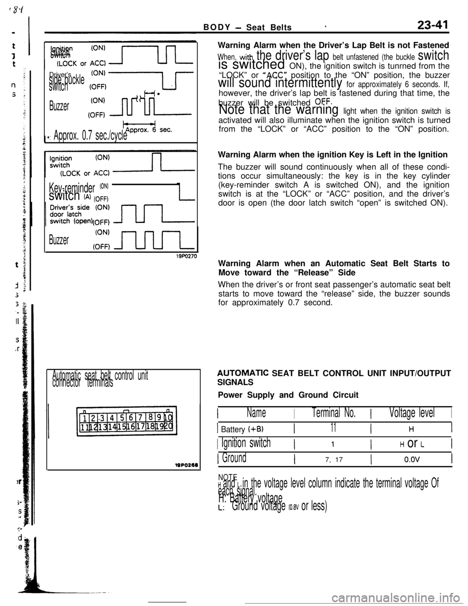
lsPo2eeWarning Alarm when the Driver’s Lap Belt is not Fastened
When, with the driver’s lap belt unfastened (the buckle switchis switched ON), the ignition switch is tunrned from the
“LOCK” or
“ACC” position to the “ON” position, the buzzer
will sound intermittently for approximately 6 seconds. If,however, the driver’s lap belt is fastened during that time, the
buzzer will be switched
OFF.
Note that the warning light when the ignition switch isactivated will also illuminate when the ignition switch is turned
from the “LOCK” or “ACC” position to the “ON” position.
Warning Alarm when the ignition Key is Left in the Ignition
The buzzer will sound continuously when all of these condi-
tions occur simultaneously: the key is in the key cylinder
(key-reminder switch A is switched ON), and the ignition
switch is at the “LOCK” or “ACC” position, and the driver’s
door is open (the door latch switch “open” is switched ON).
Warning Alarm when an Automatic Seat Belt Starts to
Move toward the “Release” Side
When the driver’s or front seat passenger’s automatic seat belt
starts to move toward the “release” side, the buzzer sounds
for approximately 0.7 second.AUTOMATlC SEAT BELT CONTROL UNIT INPUT/OUTPUT
SIGNALS
Power Supply and Ground Circuit
INameITerminal No.IVoltage levelI
I Battery (+B)I11I H 1
I Ignition switchI ’ IH or LI
IGroundI7, 17Io.ovI
NOTEH and L in the voltage level column indicate the terminal voltage Of
each signal.H: Battery voltageL:Ground voltage (0.8V or less)
Page 382 of 391
25-8EMISSION CONTROL SYSTEMS- Exhaust Gas Recirculation (EGR) System
EGR TEMPERATURE SENSOR
_Sensor part
/
/-
/* * Conneyor,
lEM0033Enaine control unit
EGR temperature sensor
Kf+
--
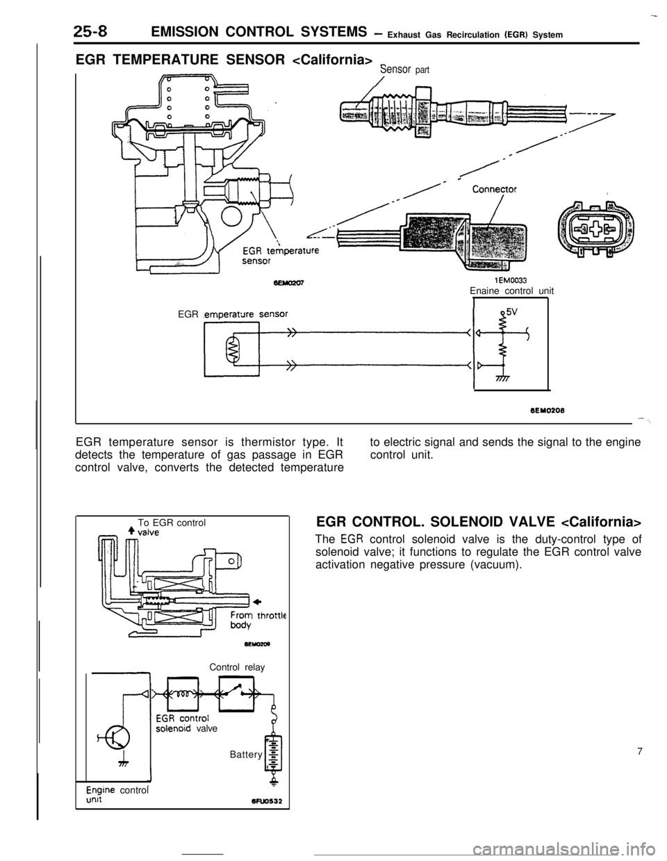
6EY0208--\EGR temperature sensor is thermistor type. It
detects the temperature of gas passage in EGR
control valve, converts the detected temperatureto electric signal and sends the signal to the engine
control unit.
To EGR control
+I thl
.ottleControl relay
solenoid valve
h
LBattery
g
0s
l$ine control5FW532EGR CONTROL. SOLENOID VALVE
The
EGR control solenoid valve is the duty-control type of
solenoid valve; it functions to regulate the EGR control valve
activation negative pressure (vacuum).
7
Page 387 of 391

EMISSION CONTROL SYSTEMS- Evaporative Emission Control System25-13
IFrom canister1
,To intake air plenum or throttle body
7EMOlPControl
relavPurge control
solenoid valve
Battery
g
6
,zEngine control
unit
From throttle body
4To purge
control
valve
SEMo2laControl relay
3:
1.
Purge control
solenoid valve
zBattery g
Engtne controlunii
bfuo532JPURGE CONTROL SOLENOID VALVE
The purge-control solenoid valve is the ON/OFF control type of
solenoid valve; it functions to control the introduction of purge
air to the intake air plenum from the canister.
PURGE CONTROL SOLENOID VALVE
The purge-control solenoid valve is the ON/OFF control type of
solenoid valve; it functions to control the activation of the
purge-control valve.
ITo throttle body11PURGE CONTROL VALVE
The purge-control valve functions to control the introduction of
purge air to the air-intake hose from the canister.
0 From canister