lock MITSUBISHI ECLIPSE 1990 Service Manual
[x] Cancel search | Manufacturer: MITSUBISHI, Model Year: 1990, Model line: ECLIPSE, Model: MITSUBISHI ECLIPSE 1990Pages: 391, PDF Size: 15.27 MB
Page 5 of 391
GENERAL
---- -~- -------l
O-l
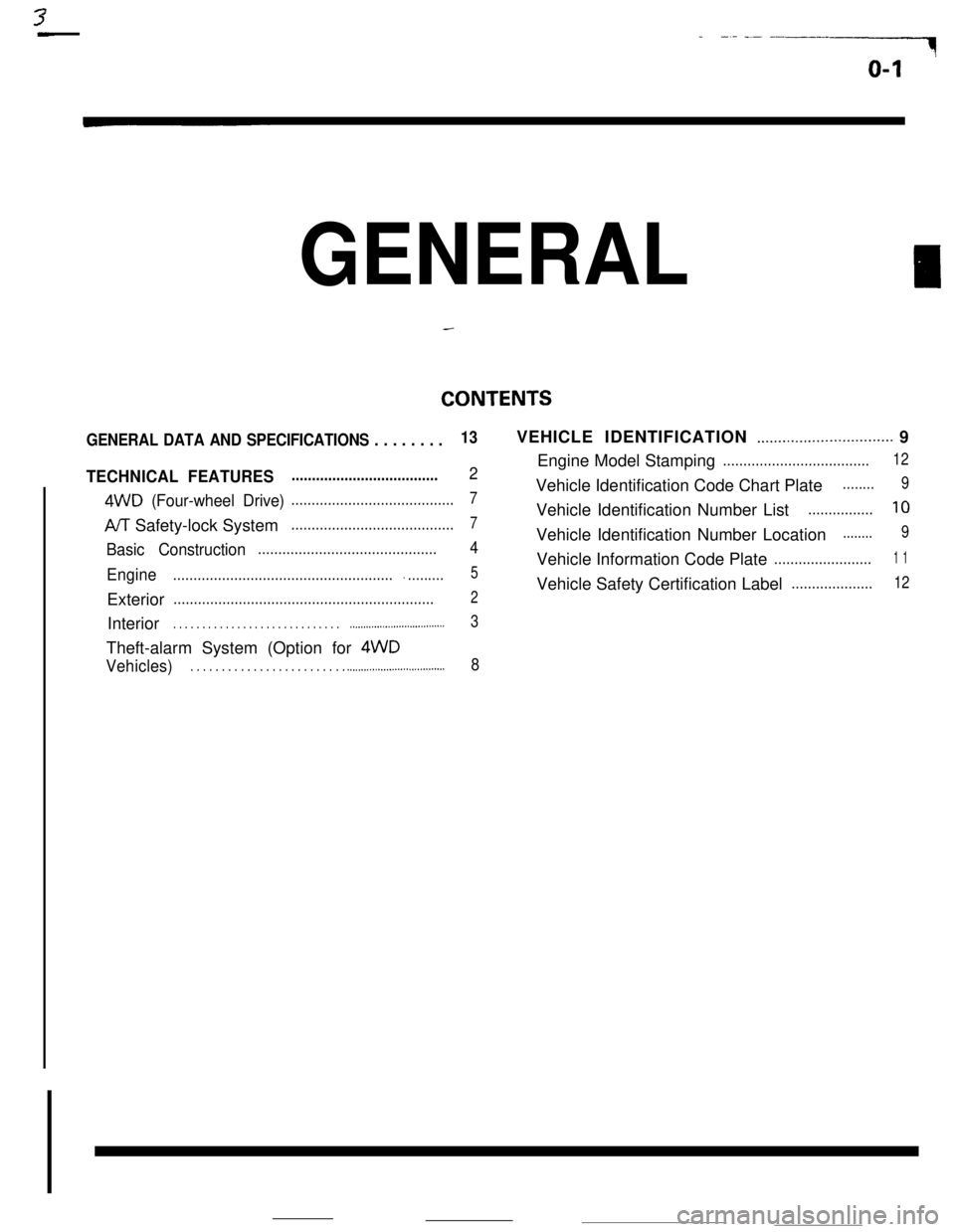
CONTENTS
GENERAL DATA AND SPECIFICATIONS . . . . . . . ..._..................._........_ 9
TECHNICAL FEATURES
4WD (Four-wheel Drive)........................................710
PJT Safety-lock Syste m........................................7
..__............................... 3
Theft-alarm System (Option for 4WD
Vehicles) . . . . . . . . . . . . . . . . . . . . . . . . . .._._........_..................... 8
Page 11 of 391
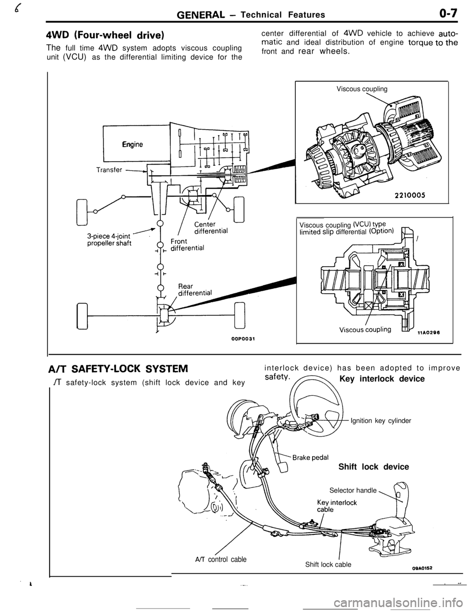
GENERAL -Technical Featureso-74WD
(Four-wheel drive)The full time 4WD system adopts viscous coupling
unit (VCU) as the differential limiting device for thecenter differential of 4WD vehicle to achieve auto-
matic and ideal distribution of engine torque to the
front and rear wheels.
r_
Engine
00P0031Viscous coupling
Viscous coupling
(VCU) VP?limited slip differential (OptIOn)
A/TSAFETY-LOCK SYSTEMinterlock device) has been adopted to improve
JT safety-lock system (shift lock device and keysafety*FNKey interlock device
Ignition key cylinder
Shift lock device
Selector handle
AIT control cableShift lock cable
~ ^.._...
Page 12 of 391
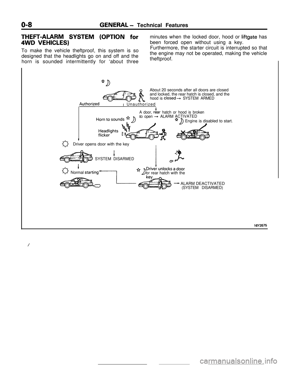
O-8GENERAL - Technical FeaturesTHEFT-ALARM SYSTEM (OPTION for4WD
VEHICLES)To make the vehicle theftproof, this system is so
designed that the headlights go on and off and the
horn is sounded intermittently for ‘about threeminutes when the locked door, hood or liftgate has
been forced open without using a key.
Furthermore, the starter circuit is interrupted so that
the engine may not be operated, making the vehicle
theftproof.
About 20 seconds after all doors are closed
and locked, the rear hatch is closed, and the
hood is closed---t SYSTEM ARMED4uthorized
I Unauthorized
A door, rf!ar hatch or hood is broken
to open + ALARMACTIVATED
Engineis disabled to start.
a-t
Driver opens door with the keyI
1SYSTEM DISARMED
0 1Normal starting-1
I
orrear hatch with the
- ALARM DEACTIVATED(SYSTEM DISARMED)
16Y3575
/
Page 16 of 391
o-12GENERAL - Vehicle Identification
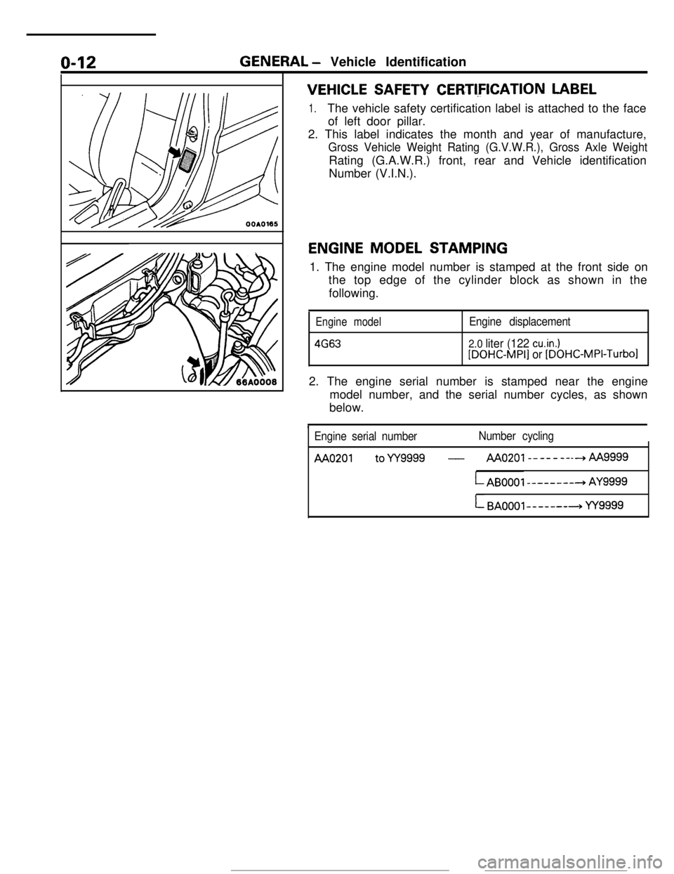
VEHICLE SAFETY CERTI,FICATION LABEL
1.The vehicle safety certification label is attached to the face
of left door pillar.
2. This label indicates the month and year of manufacture,
Gross Vehicle Weight Rating (G.V.W.R.), Gross Axle WeightRating (G.A.W.R.) front, rear and Vehicle identification
Number (V.I.N.).
ENGINE MODEL STAMPING
1. The engine model number is stamped at the front side on
the top edge of the cylinder block as shown in the
following.
Engine model
4663
Engine displacement
2.0 liter (122 cu.in.)[DOHC-MPI] or [DOHC-MPI-Turbo12. The engine serial number is stamped near the engine
model number, and the serial number cycles, as shown
below.
Engine serial numberNumber cycling
AA0201 toYY9999 -AAo201--------hAA
LAB0001 --------+ AY9999
L BAOOOl-------+ YY9999
Page 33 of 391
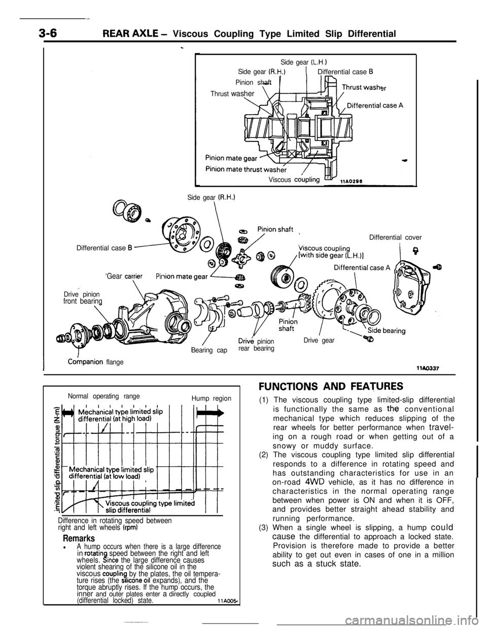
3-6REAR AXLE - Viscous Coupling Type Limited Slip Differential
Is
Side gear (L.H.)
Side gear (R.H.)1Differential case B
Pinion shaft
Thrust
washer
Viscous cokpling
3r
Side gear U3.H.)Differential case
B
, ,,Differential cover
I
‘Gear cagierPir
,Drive pinionfront bearing
Driv& pinionDrive gear
Bearing caprear bearing
ICokpanion flangellAo337
Normal operating range
Hump region
Difference in rotating speed between
right and left wheels (rpm)
RemarkslA hump occurs when there is a large differencein rotatinwheels..!speed between the right and leftlnce the large difference causes
violent shearing of the silicone oil in the
viscous couplin7.by the plates, the oil tempera-
ture rises (the SI Icone 011 expands), and the
torque abruptly rises. If the hump occurs, the
inner and outer plates enter a directly coupled(differential locked) state.llAOO5r
FUNCTIONS AND FEATURES(1) The viscous coupling type limited-slip differential
is functionally the same as
the conventional
mechanical type which reduces slipping of the
rear wheels for better performance when travel-
ing on a rough road or when getting out of a
snowy or muddy surface.
(2) The viscous coupling type limited slip differential
responds to a difference in rotating speed and
has outstanding characteristics for use in an
on-road
4WD vehicle, as it has no difference in
characteristics in the normal operating range
between when power is ON and when it is OFF,
and provides better straight ahead stability and
running performance.
(3) When a single wheel is slipping, a hump could
cause the differential to approach a locked state.
Provision is therefore made to provide a better
ability to get out even in cases of one in a million
such as a stuck state.
Page 46 of 391
-. ..- ,..__ _. I-., . . . . -. . “-Ix.. ...~‘,.;;&;,-*~;
CLUTCH- Clutch Control6-3
-
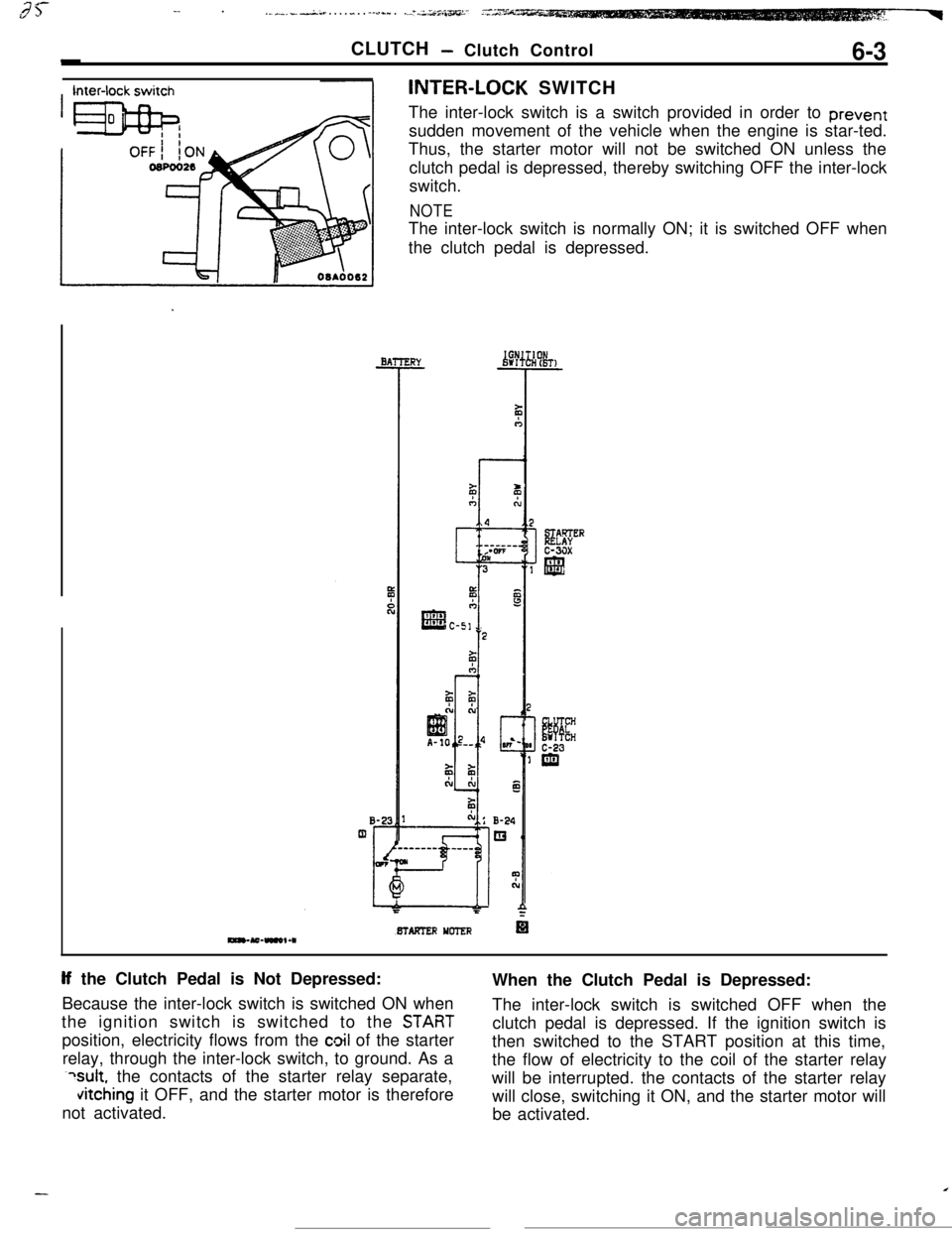
Inter-lock switchINTER-LOCK SWITCH
The inter-lock switch is a switch provided in order to prevent
sudden movement of the vehicle when the engine is star-ted.
BTAFTER YCTER
If the Clutch Pedal is Not Depressed:
Because the inter-lock switch is switched ON when
STABT
position, electricity flows from the cloil of the starter
relay, through the inter-lock switch, to ground. As a
?sult, the contacts of the starter relay separate,
vitching it OFF, and the starter motor is therefore
not activated.
Page 55 of 391
ELECTRICAL - Fuses8-3q
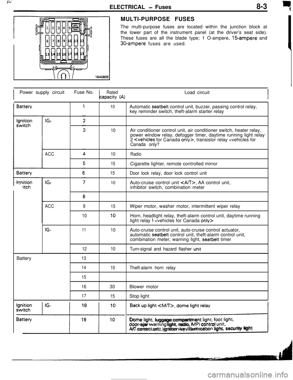
rMULTI-PURPOSE FUSES
The multi-purpose fuses are located within the junction block at
the lower part of the instrument panel (at the driver’s seat side).
These fuses are all the blade type; 1 O-ampere, 15-ampere and
30-ampere fuses are used.
IPower supply circuitFuse No.
RatedLoad circuitapacity
(A)IBattery
t-lonition,itchBattery
IGz
ACC
IG,
10
10
10
15
15
10Automatic seatbelt control unit, buzzer, passing control relay,
key reminder switch, theft-alarm starter relay
Air conditioner control unit, air conditioner switch, heater relay,
power window relay, defogger timer, daytime running light relay
2
Door lock relay, door lock control unitAuto-cruise control unit
, AA control unit,
inhibitor switch, combination meter
ACC
IGI9
1011
12
1315
10
10
10Wiper motor, washer motor, intermittent wiper relay
Horn, headlight relay, theft-alarm control unit, daytime running
light relay
1
automatic seatbelt control unit, theft-alarm control unit,
combination meter, warning light, seatbelt timer
Turn-signal and hazard flasher u.nit
14
15
16
17
10Theft-alarm horn relay
30Blower motor
15Stop light
Back up light
CM/T>, dome light relay
!Dome light. luggage compartment
Irght, foot. Irght.door-ajar warntng light, radio, MPI control unrt.AK control unit, ignition key illumination light.security lightI
Page 56 of 391
_--
8-4ELECTRICAL - Fuses / Diagnosis System
61543
2
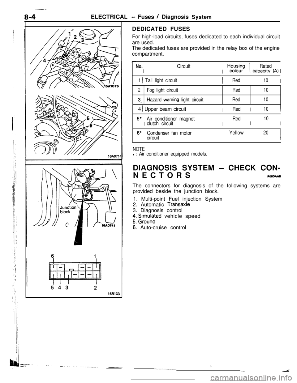
16R133lDEDICATED FUSES
For high-load circuits, fuses dedicated to each individual circuit
are used.
The dedicated fuses are provided in the relay box of the engine
compartment.
No.
I
Circuit
I
H,“d;;-;I
Rated
canacitv (A)I
1 1 Tail light circuitIRedI10I
2Fog light circuitRed10
3,.Hazard warning light circuitRed10
4 ) Upper beam circuitIRedI10I
5’
I
Air conditioner magnet
I
Red
I
10
clutch circuitI
6’Condenser fan motorYellow20
circuitI
NOTEl : Air conditioner equipped models.DIAGNOSIS SYSTEM
- CHECK CON-
NECTORS
nmcwaBThe connectors for diagnosis of the following systems are
provided beside the junction block.
1. Multi-point Fuel injection System
2. Automatic
Transaxle.3. Diagnosis control
z. grm.rlnaFd vehicle speed
6: Auto-cruise control
:..--.-__-.
Page 57 of 391
3i
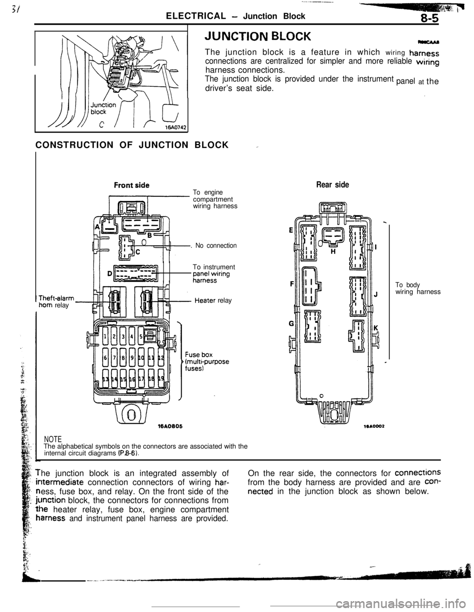
ELECTRICAL - Junction Block8-5JUNCTION
BLOCKThe junction block is a feature in which wiring
hamess
connections are centralized for simpler and more reliable wiringharness connections.
The junction block is provided under the instrumentdriver’s seat side.panelat the
CONSTRUCTION OF JUNCTION BLOCK
_.rheft-alarm
iom relay
To enginecompartment
wiring harness
. No connectionTo instrument
;;;+$ring
.’ ./%A0805relay
Rear side
NOTEThe alphabetical symbols on the connectors are associated with the
internal circuit diagrams
(PB-6).To bodywiring harness
he junction block is an integrated assembly ofltermediate connection connectors of wiring
har-ess, fuse box, and relay. On the front side of the
unction block, the connectors for connections from
le heater relay, fuse box, engine compartment
amess and instrument panel harness are provided.On the rear side, the connectors for connections
from the body harness are provided and are
con-
netted in the junction block as shown below.
Page 58 of 391
__._._ -.. .-
8-6ELECTRICAL - Junction Block
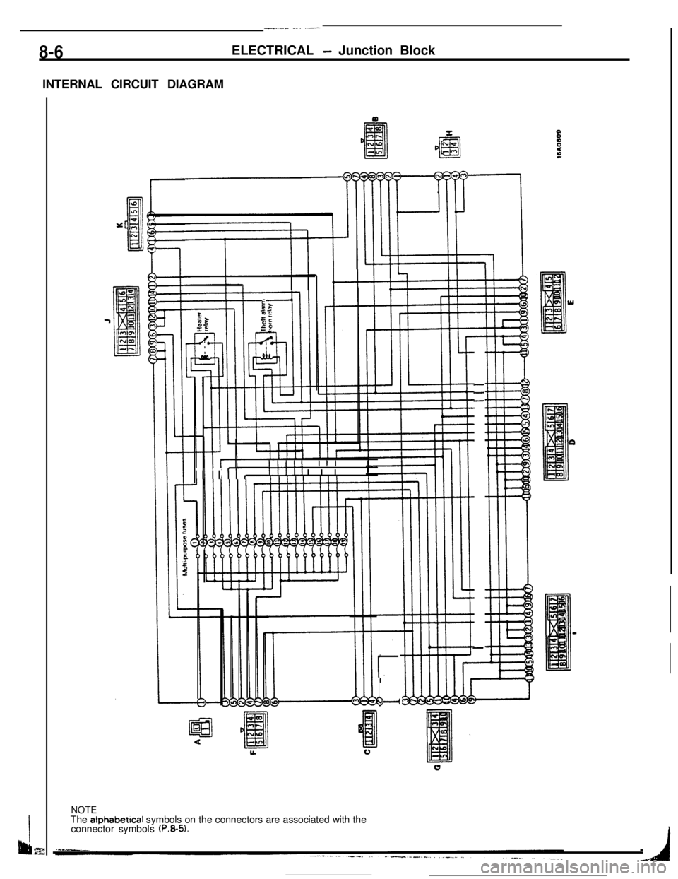
INTERNAL CIRCUIT DIAGRAM
---
-
Illll IIII
I II Irr,Illll IIII
r
L”
NOTEThe alphabetical symbols on the connectors are associated with the
connector symbols
(P.8-5).