fuel type MITSUBISHI ECLIPSE 1990 User Guide
[x] Cancel search | Manufacturer: MITSUBISHI, Model Year: 1990, Model line: ECLIPSE, Model: MITSUBISHI ECLIPSE 1990Pages: 391, PDF Size: 15.27 MB
Page 120 of 391
14-8
rFUEL SYSTEM
-Fuel Supply and Fuel Pressure Control
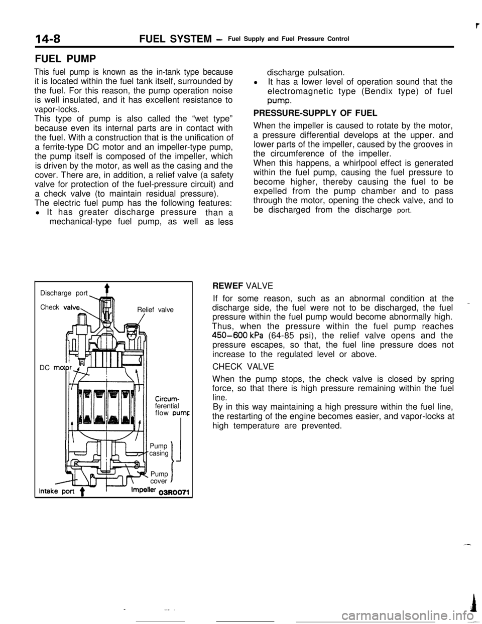
FUEL PUMP
This fuel pump is known as the in-tank type becauseit is located within the fuel tank itself, surrounded by
the fuel. For this reason, the pump operation noise
is well insulated, and it has excellent resistance to
vapor-locks.This type of pump is also called the “wet type”
because even its internal parts are in contact with
the fuel. With a construction that is the unification of
a ferrite-type DC motor and an impeller-type pump,
the pump itself is composed of the impeller, which
is driven by the motor, as well as the casing and the
cover. There are, in addition, a relief valve (a safety
valve for protection of the fuel-pressure circuit) and
a check valve (to maintain residual pressure).
The electric fuel pump has the following features:
l It has greater discharge pressure
mechanical-type fuel pump, as wellthan a
as lessdischarge pulsation.
lIt has a lower level of operation sound that the
electromagnetic type (Bendix type) of fuelpump.
PRESSURE-SUPPLY OF FUEL
When the impeller is caused to rotate by the motor,
a pressure differential develops at the upper. and
lower parts of the impeller, caused by the grooves in
the circumference of the impeller.
When this happens, a whirlpool effect is generated
within the fuel pump, causing the fuel pressure to
become higher, thereby causing the fuel to be
expelled from the pump chamber and to pass
through the motor, opening the check valve, and to
be discharged from the discharge port.
Discharge port
4Check!nRelief valve
DC mo
-lllll1 I/
Circum-ferential
flow pumr
II’ f-Pump
casing
J
Pumpcovert
lntakler 03R0071REWEF VALVE
If for some reason, such as an abnormal condition at the
_discharge side, the fuel were not to be discharged, the fuel
pressure within the fuel pump would become abnormally high.
Thus, when the pressure within the fuel pump reaches
450-600 kPa (64-85 psi), the relief valve opens and the
pressure escapes, so that, the fuel line pressure does not
increase to the regulated level or above.
CHECK VALVE
When the pump stops, the check valve is closed by spring
force, so that there is high pressure remaining within the fuel
line.By in this way maintaining a high pressure within the fuel line,
the restarting of the engine becomes easier, and vapor-locks at
high temperature are prevented.
-
-_..I
-~
Page 121 of 391
FUEL SYSTEM -Fuel Supply and Fuel Pressure Control14-9
03Poo4:Diaphragm
from intake
4Fuel from delivery pipe
4m
B(42.7)QQ
2
sl -196 2
(26.4) g
t
$!a d
9
0)Positive5 z‘. pressure
(E.2)
w
FUEL FILTERA high-pressure type filter is installed at the delivery end of the
fuel pump.
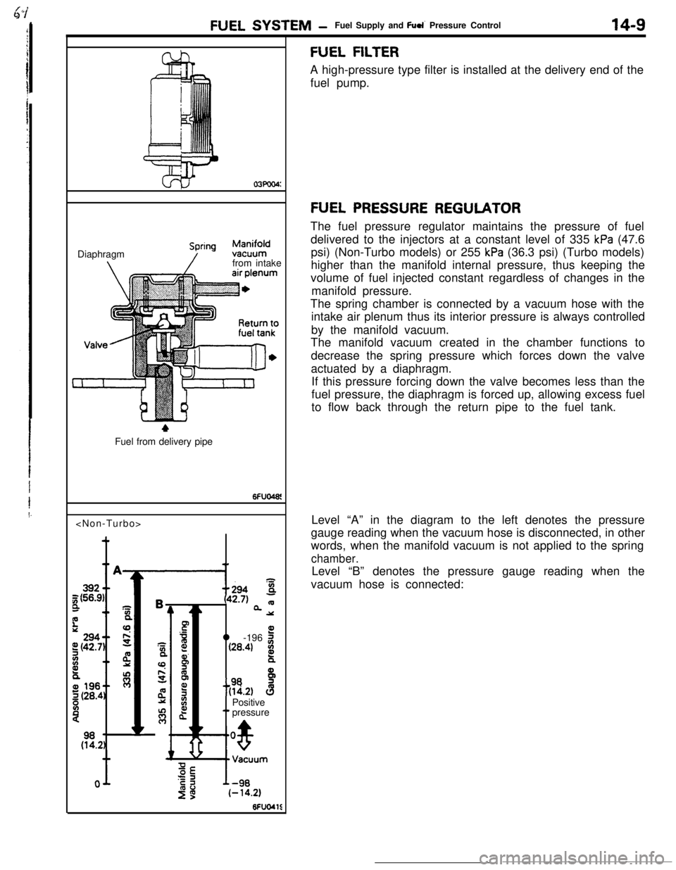
FUEL PRESSURE REGULATORThe fuel pressure regulator maintains the pressure of fuel
delivered to the injectors at a constant level of 335
kPa (47.6
psi) (Non-Turbo models) or 255
kPa (36.3 psi) (Turbo models)
higher than the manifold internal pressure, thus keeping the
volume of fuel injected constant regardless of changes in the
manifold pressure.
The spring chamber is connected by a vacuum hose with the
intake air plenum thus its interior pressure is always controlled
by the manifold vacuum.
The manifold vacuum created in the chamber functions to
decrease the spring pressure which forces down the valve
actuated by a diaphragm.
If this pressure forcing down the valve becomes less than the
fuel pressure, the diaphragm is forced up, allowing excess fuel
to flow back through the return pipe to the fuel tank.
Level “A” in the diagram to the left denotes the pressure
gauge reading when the vacuum hose is disconnected, in other
words, when the manifold vacuum is not applied to the spring
chamber.Level “B” denotes the pressure gauge reading when the
vacuum hose is connected:
Page 125 of 391
FUEL SYSTEM- Intake Air Control
SPECIFICATIONS
ternsThrottle body
Throttle bore diametermm
(in.1Fast idle air valve
TwValve closing temperature
“C (“F)
Idle speed control servo
TypeSpecifications
60 (2.362)
WAX type
Approximately 50
(122)Stepper motor type
FAST IDLE AIR VALVEEngine coolant
LAir valve
Waxpellet
Valve seat
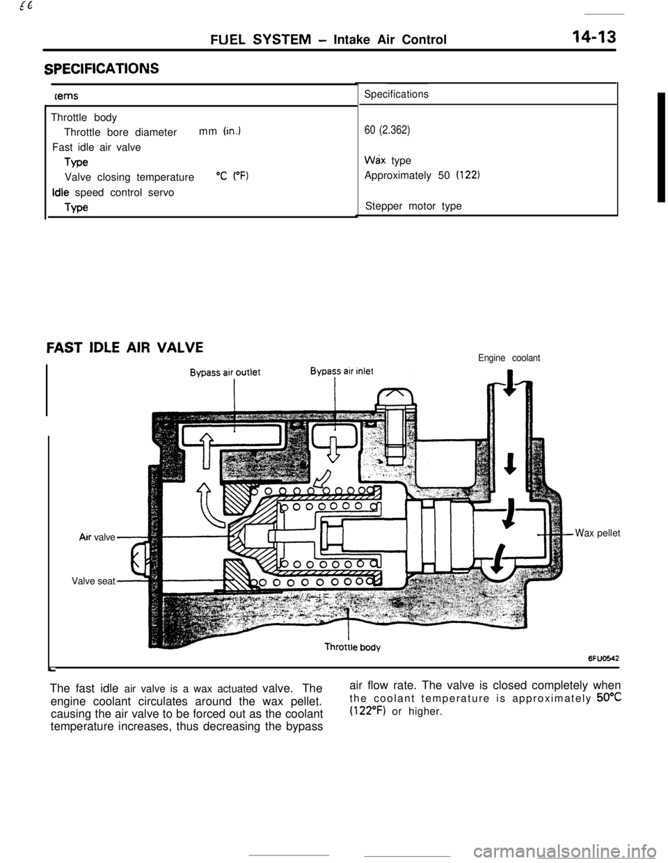
6FUO642The fast idle air valve is a wax actuated valve. The
engine coolant circulates around the wax pellet.
causing the air valve to be forced out as the coolant
temperature increases, thus decreasing the bypassair flow rate. The valve is closed completely when
the coolant temperature is approximately 50°C
(122°F) or higher.
Page 126 of 391
14-14
.._~- ---.FUEL SYSTEM
- Sensors
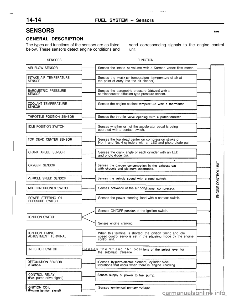
SENSORSRlUGENERAL DESCRIPTION
The types and functions of the sensors are as listedsend corresponding signals to the engine control
below. These sensors detect engine conditions and
unit.
SENSORSFUNCTION
AIR FLOW SENSOR
fSenses the intake arr volume with a Karman vortex flow meter.
INTAKE AIR TEMPERATURE
SENSORSenses the Intake air temperature (temperature of air at
the point of entry into the air cleaner).I
BAROMETRIC PRESSURE
SENSORISenses the barometric pressure faltrtude) wrth a
semiconductor diffusion type pressure sensor.
$;;OOf;T TEMPERATURESenses the engine coolant tern
THROTTLE
POSITISenses the throttle
tI
IDLE POSITION SWITCHSenses whether or not the accelerator pedal is being
operated with a contact switch.
Senses the top dead center on compression stroke of
NO. 1 and No. 4 cylinders with an LED and photo diode pair.
CRANK ANGLE SENSORSenses the crank angle of each cylinder with an LED
and photo diodepair.
T
OXYGEN SENSORSenses
actrvation of the air con
POWER STEERING OIL
PRESSURE SWITCHc-lSenses the power steering ‘load with a contact switch.
IGNITION SWITCHSenses ON/OFF
posrtion of the ignition switch.I
Senses engine cranking.
,
IGNITION TIMING
ADJUSTMENT TERMINALWhen this terminal is shorted, the ignition timing and idle
speed control servo is set in the adjustrng mode by the enginecontrol unit.
INHIBITOR SWITCHSenses the *P” and “N” positthe automatic transaxle.Senses.
by pieto-electric element,. cylinder block
vibrations that occur when there ISengineknocking.
CONTROL RELAY
(Fuel pump drive signal)
lFnorne ianitron sianal!Senses ignrtton coil prIman/ voltage.
Page 131 of 391
FUEL SYSTEM - Sensors
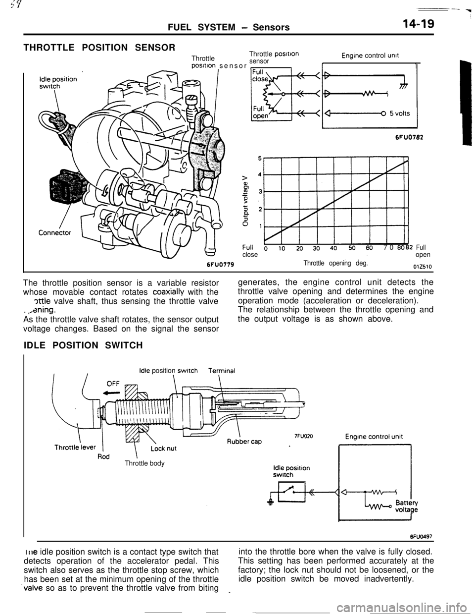
THROTTLE POSITION SENSOR
ThrottleThrottle
posItIon
sensorposltion sensor
,_Il-
Engine control unit
1
6FU0782
Throttle opening deg.
Full o IO 20 30 4070 0002closeFullopenThe throttle position sensor is a variable resistor
whose movable contact rotates
coaxially with the
cattle valve shaft, thus sensing the throttle valve
.
,,ening.As the throttle valve shaft rotates, the sensor outputgenerates, the engine control unit detects the
throttle valve opening and determines the engine
operation mode (acceleration or deceleration).
The relationship between the throttle opening and
the output voltage is as shown above.
voltage changes. Based on the signal the sensor
IDLE POSITION SWITCH
Idle positionswitchTermtnal
7FUO20Throttle body
Idle positlonswitch
I6Fw497I
rle idle position switch is a contact type switch thatinto the throttle bore when the valve is fully closed.
detects operation of the accelerator pedal. ThisThis setting has been performed accurately at the
switch also serves as the throttle stop screw, whichfactory; the lock nut should not be loosened, or the
has been set at the minimum opening of the throttleidle position switch be moved inadvertently.
‘valve so as to prevent the throttle valve from biting_
Page 134 of 391
14-22FUEL SYSTEM - Sensors
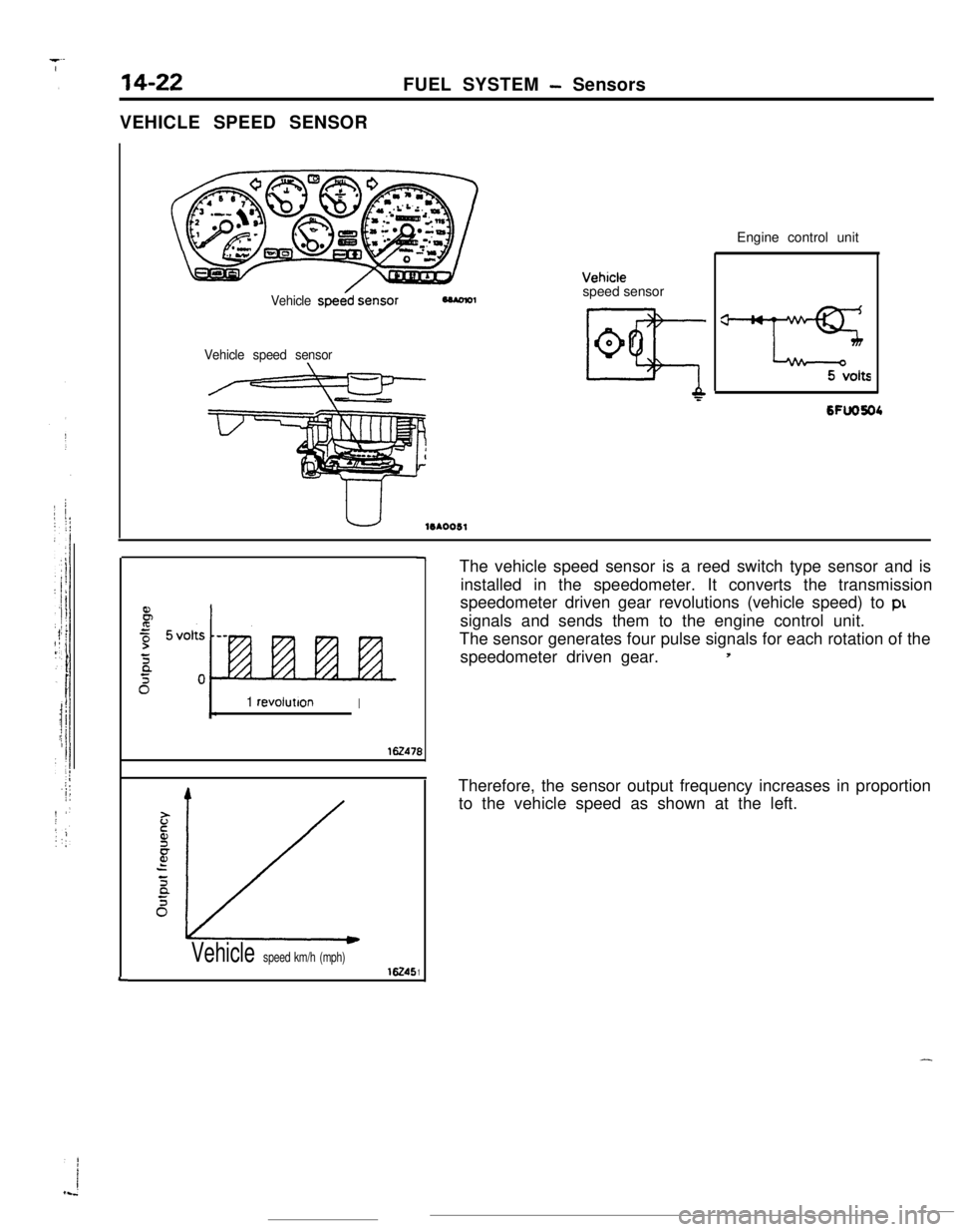
VEHICLE SPEED SENSOR
L
Vehicle speessensor
Vehicle speed sensor
10*0051speed sensorEngine control unit
6FlJO604
1 revoluttonI
‘r’471
16245
7
B
1Vehicle speed km/h (mph)The vehicle speed sensor is a reed switch type sensor and is
installed in the speedometer. It converts the transmission
speedometer driven gear revolutions (vehicle speed) to
ptsignals and sends them to the engine control unit.
The sensor generates four pulse signals for each rotation of the
speedometer driven gear.
5Therefore, the sensor output frequency increases in proportion
to the vehicle speed as shown at the left.
-
Page 157 of 391
3-d__- .
FUEL SYSTEM
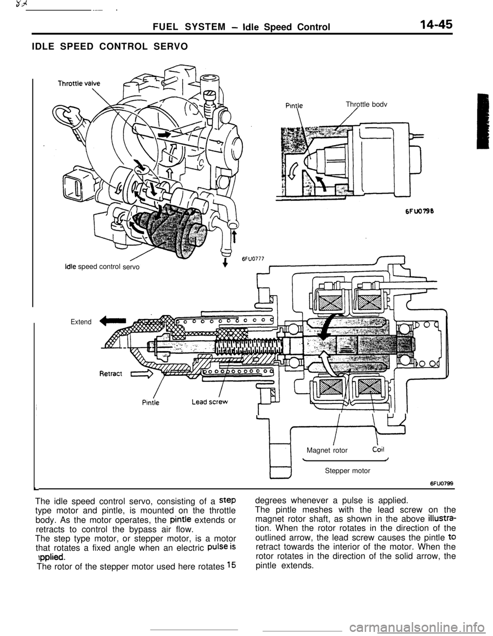
-Idle Speed Control14-45IDLE SPEED CONTROL SERVO
L
PtntleThrottle bodv
Idle speed control
servo
Extend
7 -IMagnet rotordoil
/Stepper motor
6FUO799The idle speed control servo, consisting of a
steptype motor and pintle, is mounted on the throttle
body. As the motor operates, the pintie extends or
retracts to control the bypass air flow.
The step type motor, or stepper motor, is a motor
that rotates a fixed angle when an electric
Pulse is
rpplied.The rotor of the stepper motor used here rotates
15degrees whenever a pulse is applied.
The pintle meshes with the lead screw on the
magnet rotor shaft, as shown in the above
illustra-tion. When the rotor rotates in the direction of the
outlined arrow, the lead screw causes the pintle t0
retract towards the interior of the motor. When the
rotor rotates in the direction of the solid arrow, the
pintle extends.
Page 169 of 391
FUEL SYSTEMAir Flow Sensor (AFSI Filter Reset Control
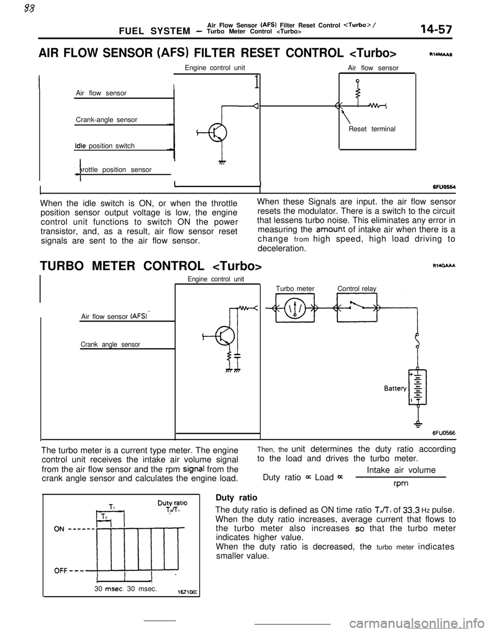
AIR FLOW SENSOR (AFS) FILTER RESET CONTROL
I1Air flow sensor
Crank-angle sensorIdle position switch
Throttle position sensor
4Air flow sensor
//\\ -
\Reset terminal
RllruAs
6FlJo664I11When the idle switch is ON, or when the throttleWhen these Signals are input. the air flow sensor
position sensor output voltage is low, the engineresets the modulator. There is a switch to the circuit
control unit functions to switch ON the powerthat lessens turbo noise. This eliminates any error in
transistor, and, as a result, air flow sensor resetmeasuring the
.amount of intake air when there is a
signals are sent to the air flow sensor.change from high speed, high load driving to
deceleration.
TURBO METER CONTROL
Air flow sensor
(AFSI ’
Crank angle sensorEngine control unit
BT
Rl4QAAATurbo meterControl relay
The turbo meter is a current type meter. The engine
control unit receives the intake air volume signal
from the air flow sensor and the rpm
signal from the
crank angle sensor and calculates the engine load.Then, the unit determines the duty ratio according
to the load and drives the turbo meter.
Intake air volume
Duty ratio
it Load 0:rwDuty ratio
The duty ratio is defined as ON time ratio
TJT, of 33.3 Hz pulse.
When the duty ratio increases, average current that flows to
the turbo meter also increases
so that the turbo meter
indicates higher value.
When the duty ratio is decreased, the turbo meter indicates
smaller value.
cI30
msec. 30 msec.1621cm:
Page 170 of 391
._ ..-
14-58
.-FUEL SYSTEM
- Accelerator Components
-7
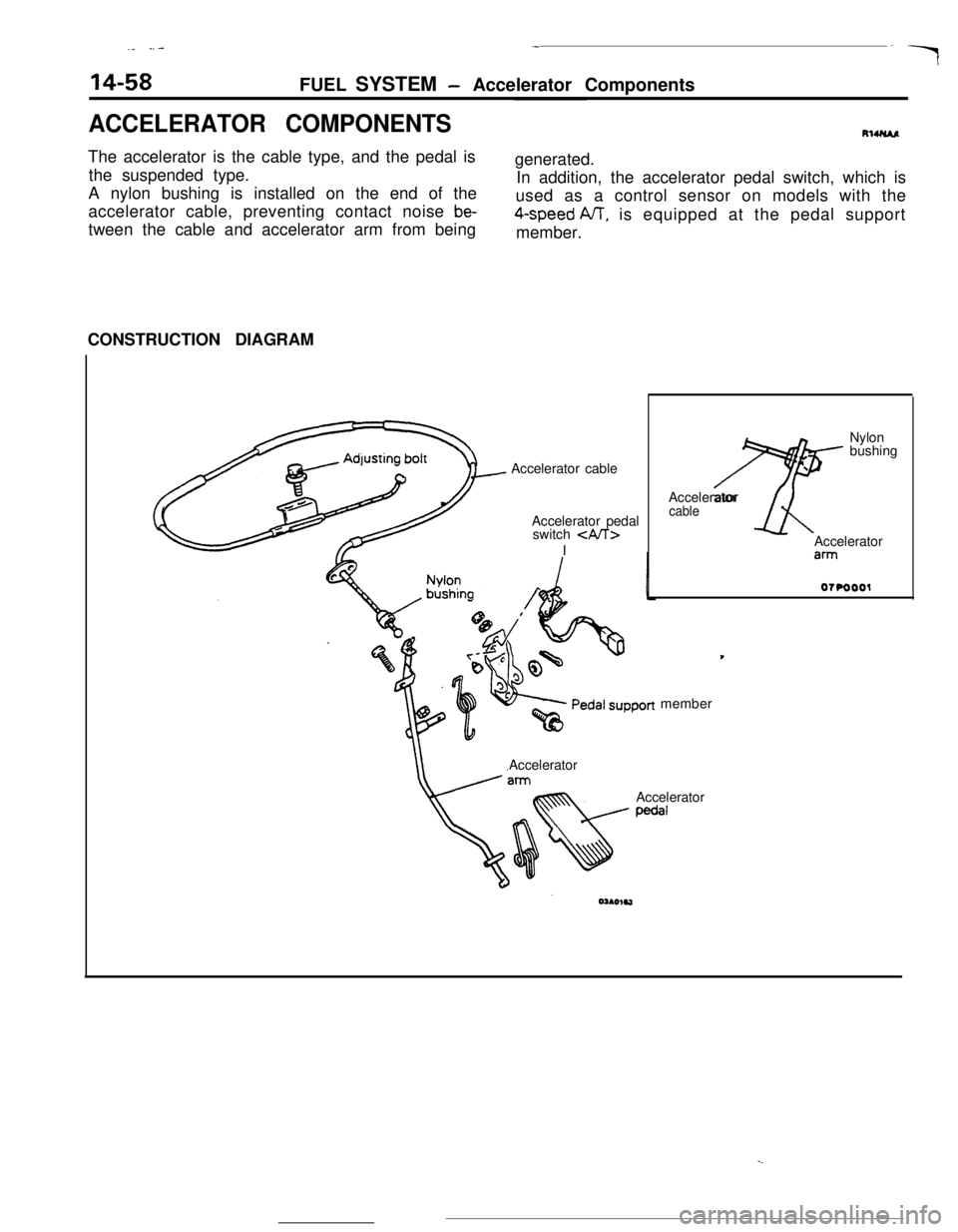
ACCELERATOR COMPONENTSRlUUAAThe accelerator is the cable type, and the pedal is
the suspended type.
A nylon bushing is installed on the end of the
accelerator cable, preventing contact noise
be-tween the cable and accelerator arm from beinggenerated.
In addition, the accelerator pedal switch, which is
used as a control sensor on models with the4-speed NT, is equipped at the pedal support
member.
CONSTRUCTION DIAGRAM
Accelerator cable
Accelerator pedal
switch
\Accelerator
cableAccelerator
ahmember
Accelerator
Accelerator
pedal
Page 171 of 391
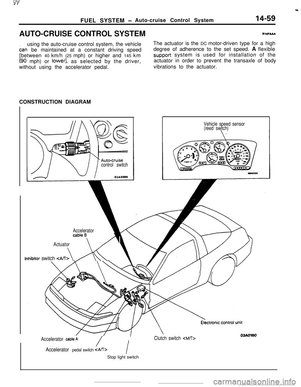
FUEL SYSTEM -Auto-cruise Control System14-59AUTO-CRUISE CONTROL SYSTEMRIIPA&A
using the auto-cruise control system, the vehicle
oar-rbe maintained at a constant driving speed
[between 40 km/h (25 mph) or higher and 145 km
(90 mph) or lower], as selected by the driver,
without using the accelerator pedal.The actuator is the DC motor-driven type for a high
degree of adherence to the set speed. A flexiblesupport system is used for installation of the
actuator in order to prevent the transaxle of body
vibrations to the actuator.
CONSTRUCTION DIAGRAM
control switchOJAO2SS
Accelerator
Actuator
ab’ea\ A
Inhibitor switch
(reed switch)
Accelerator cab1e.A/IClutch switch
/Accelerator pedal switch IStop light switch