fuel type MITSUBISHI ECLIPSE 1990 Owner's Manual
[x] Cancel search | Manufacturer: MITSUBISHI, Model Year: 1990, Model line: ECLIPSE, Model: MITSUBISHI ECLIPSE 1990Pages: 391, PDF Size: 15.27 MB
Page 186 of 391
14-74
_ ,.-..FUEL SYSTEM
- Auto-cruise Control System
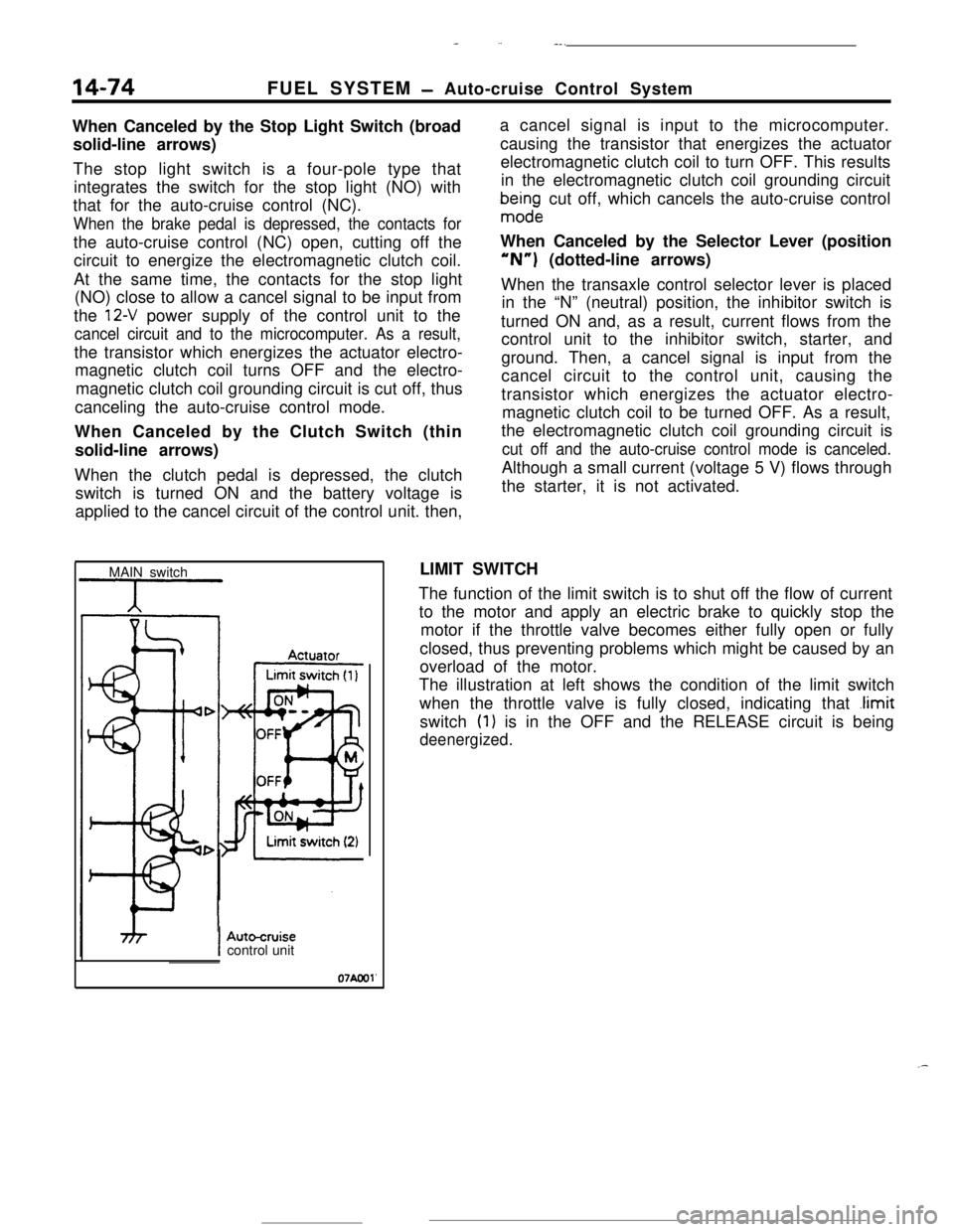
When Canceled by the Stop Light Switch (broad
solid-line arrows)
The stop light switch is a four-pole type that
integrates the switch for the stop light (NO) with
that for the auto-cruise control (NC).
When the brake pedal is depressed, the contacts forthe auto-cruise control (NC) open, cutting off the
circuit to energize the electromagnetic clutch coil.
At the same time, the contacts for the stop light
(NO) close to allow a cancel signal to be input from
the
12-V power supply of the control unit to the
cancel circuit and to the microcomputer. As a result,the transistor which energizes the actuator electro-
magnetic clutch coil turns OFF and the electro-
magnetic clutch coil grounding circuit is cut off, thus
canceling the auto-cruise control mode.
When Canceled by the Clutch Switch (thin
solid-line arrows)
When the clutch pedal is depressed, the clutch
switch is turned ON and the battery voltage is
applied to the cancel circuit of the control unit. then,a cancel signal is input to the microcomputer.
causing the transistor that energizes the actuator
electromagnetic clutch coil to turn OFF. This results
in the electromagnetic clutch coil grounding circuit
bma$ndge cut off, which cancels the auto-cruise control
When Canceled by the Selector Lever (position“N”) (dotted-line arrows)
When the transaxle control selector lever is placed
in the “N” (neutral) position, the inhibitor switch is
turned ON and, as a result, current flows from the
control unit to the inhibitor switch, starter, and
ground. Then, a cancel signal is input from the
cancel circuit to the control unit, causing the
transistor which energizes the actuator electro-
magnetic clutch coil to be turned OFF. As a result,
the electromagnetic clutch coil grounding circuit is
cut off and the auto-cruise control mode is canceled.Although a small current (voltage 5 V) flows through
the starter, it is not activated.
MAIN switchLIMIT SWITCH
The function of the limit switch is to shut off the flow of current
to the motor and apply an electric brake to quickly stop the
motor if the throttle valve becomes either fully open or fully
closed, thus preventing problems which might be caused by an
overload of the motor.
The illustration at left shows the condition of the limit switch
when the throttle valve is fully closed, indicating that
.limitswitch
(1) is in the OFF and the RELEASE circuit is being
deenergized.
IAutocruisecontrol unit
07Aool'
.-
Page 187 of 391
_-.-, ._ u .-, 4. ::; bt-i 3,. F-7__ . ._,_ _ ” -- --.-....
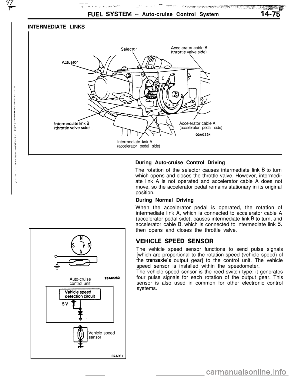
FUEL SYSTEM- Auto-cruise Control System14-75INTERMEDIATE LINKS
Intermediate
iink A(accelerator pedal side)Accelerator cable
A
(accelerator pedal side)
03AO224During Auto-cruise Control Driving
The rotation of the selector causes intermediate link
B to turn
which opens and closes the throttle valve. However, intermedi-
ate link A is not operated and accelerator cable A does not
move, so the accelerator pedal remains stationary in its original
position.During Normal Driving
When the accelerator pedal is operated, the rotation of
intermediate link A, which is connected to accelerator cable A
(accelerator pedal side), causes intermediate link
B to turn, and
accelerator cable
B, which is connected to intermediate link B,then opens and closes the throttle valve.
N
0
s -?s
*=Auto-cruise
control unit
13AOO62Vehicle speed
sensor07Aml
VEHICLE SPEED SENSORThe vehicle speed sensor functions to send pulse signals
[which are proportional to the rotation speed (vehicle speed) of
the transaxle’s output gear] to the control unit. The vehicle
speed sensor is installed within the speedometer.
The vehicle speed sensor is the reed switch type; it generates
four pulse signals for each rotation of the output gear. This
sensor is also used in common for other electronic control
systems.
Page 188 of 391
- -----.--..
14-76FUEL SYSTEM -Auto-cruise Control System
Ignition switch
IGI
9
RESUActuator electro-
Microcomputer
1 T 1
rn’Auto-cruise control unit
Autocruisecontrol switch
IGlMAIN
;FF -+++&Control unit
power supply
terminal voltage
03AO264NC: Normally closed
07*0040
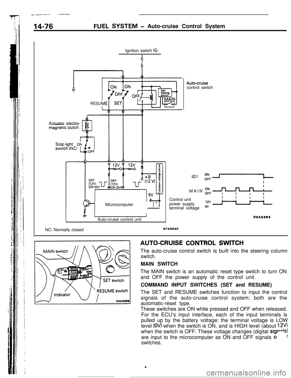
AUTO-CRUISE CONTROL SWITCH
The auto-cruise control switch is built into the steering column
switch.MAIN SWITCH
The MAIN switch is an automatic reset type switch to turn ON
and OFF the power supply of the control unit.
COMMAND INPUT SWITCHES (SET and RESUME)
The SET and RESUME switches function to input the control
signals of the auto-cruise control system; both are the
automatic-reset type.
These switches are ON while pressed and OFF when released.
For the ECU’s input interface, each of the input terminals is
pulled up by the battery voltage; the terminal voltage is LOW
level
(OV) when the switch is ON, and is HIGH level (about 12V)when the switch is OFF. These voltage changes (digital
sig*)are input to the microcomputer as ON and OFF signals
o.:
switches.
.
Page 189 of 391
-- --.-*-.e *._,_-.&” :,.>~‘c,-.y~~ 7, . . --
FUEL SYSTEM- Auto-cruise Control System14-77
(For stop light)
OFF +-ON
0N -+-OFF
(For auto-cruise control)
16RO99r4 3
12
NCNO-w-w
I/0l-COFFOFF*~ON4
321NO: Normally opened
NC: Normally closed
07AOOl:
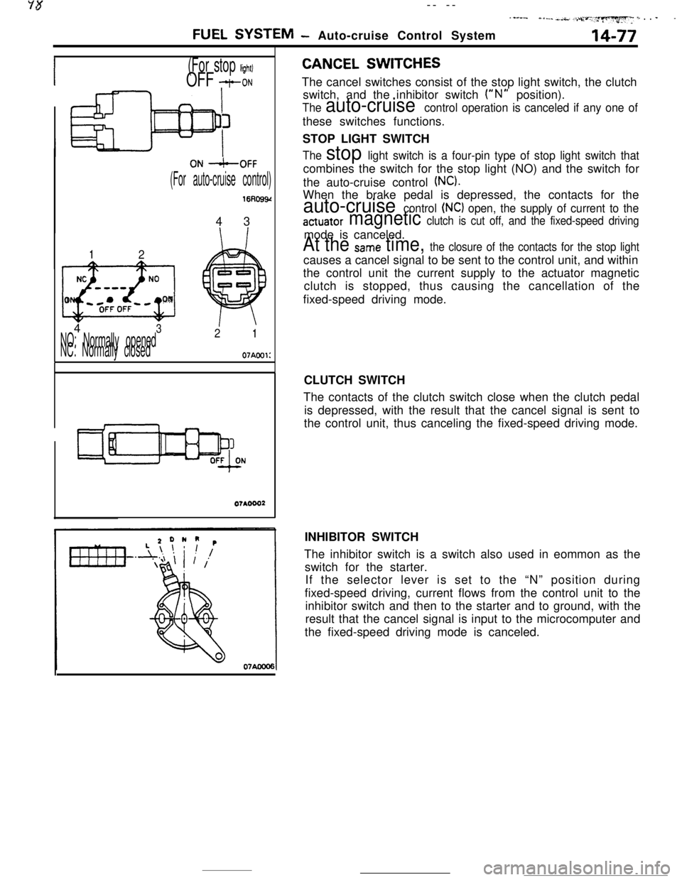
CANCEL SWITCHESThe cancel switches consist of the stop light switch, the clutch
switch, and the inhibitor switch
(“N” position).
The auto-cruise control operation is canceled if any one ofthese switches functions.
STOP LIGHT SWITCH
The stop light switch is a four-pin type of stop light switch thatcombines the switch for the stop light (NO) and the switch for
the auto-cruise control
(NC).When the brake pedal is depressed, the contacts for the
auto-cruise control (NC) open, the supply of current to the
actuator magnetic clutch is cut off, and the fixed-speed drivingmode is canceled.
At the Same time, the closure of the contacts for the stop lightcauses a cancel signal to be sent to the control unit, and within
the control unit the current supply to the actuator magnetic
clutch is stopped, thus causing the cancellation of the
fixed-speed driving mode.
CLUTCH SWITCH
The contacts of the clutch switch close when the clutch pedal
is depressed, with the result that the cancel signal is sent to
the control unit, thus canceling the fixed-speed driving mode.
INHIBITOR SWITCH
The inhibitor switch is a switch also used in eommon as the
switch for the starter.
If the selector lever is set to the “N” position during
fixed-speed driving, current flows from the control unit to the
inhibitor switch and then to the starter and to ground, with the
result that the cancel signal is input to the microcomputer and
the fixed-speed driving mode is canceled.
Page 274 of 391
21-50AUTOMATIC TRANSAXLE - Transaxle Control
Vehicle
sensorspeedTerminal voltage
(VI
1
5
\*Fluidtemperature
02080PCI 1750409VEHICLE-SPEED SENSOR
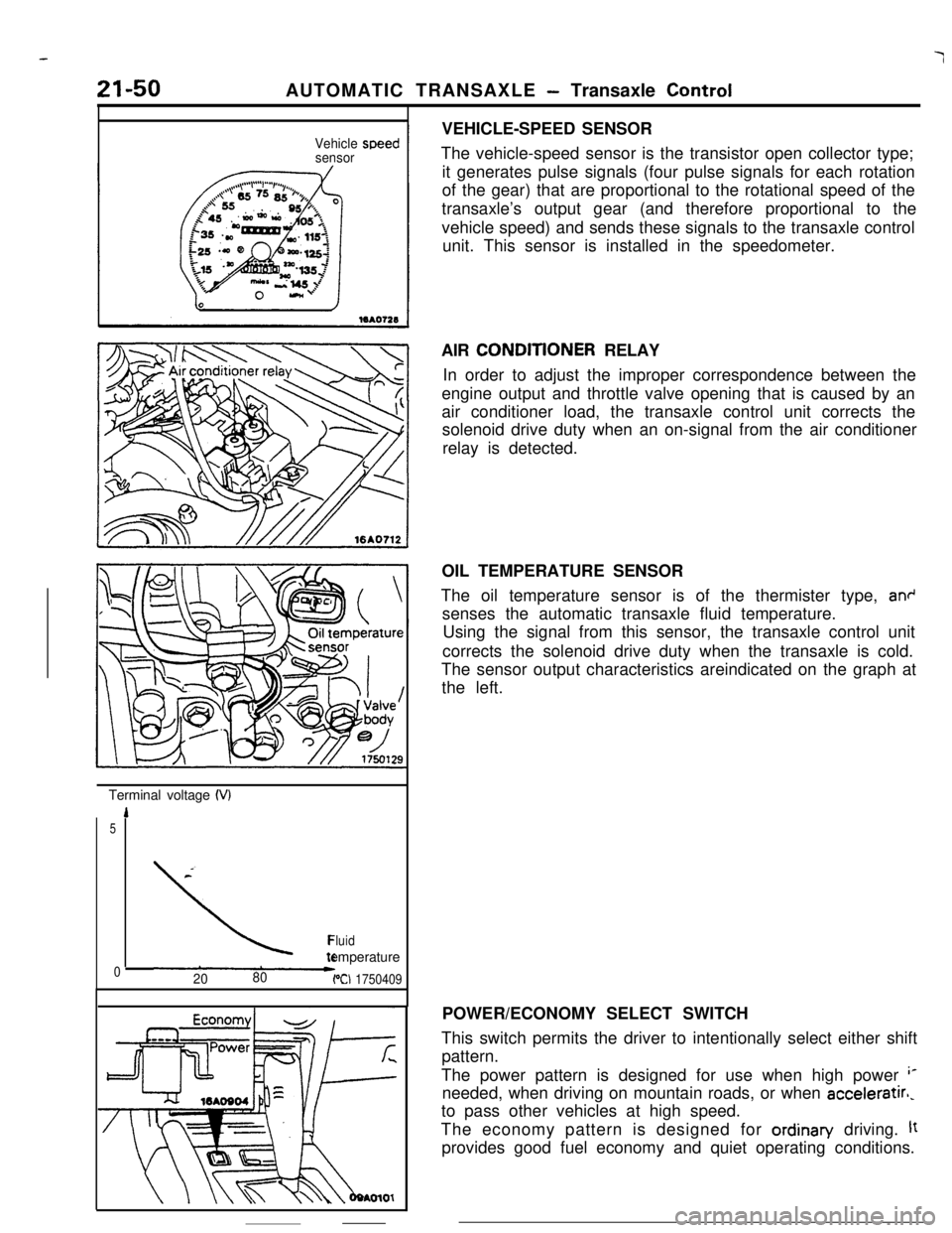
The vehicle-speed sensor is the transistor open collector type;
it generates pulse signals (four pulse signals for each rotation
of the gear) that are proportional to the rotational speed of the
transaxle’s output gear (and therefore proportional to the
vehicle speed) and sends these signals to the transaxle control
unit. This sensor is installed in the speedometer.
AIR CONDlTlONER RELAY
In order to adjust the improper correspondence between the
engine output and throttle valve opening that is caused by an
air conditioner load, the transaxle control unit corrects the
solenoid drive duty when an on-signal from the air conditioner
relay is detected.
OIL TEMPERATURE SENSOR
The oil temperature sensor is of the thermister type,
an+senses the automatic transaxle fluid temperature.
Using the signal from this sensor, the transaxle control unit
corrects the solenoid drive duty when the transaxle is cold.
The sensor output characteristics areindicated on the graph at
the left.
POWER/ECONOMY SELECT SWITCH
This switch permits the driver to intentionally select either shift
pattern.
The power pattern is designed for use when high power
‘*needed, when driving on mountain roads, or when acceleratirl,
to pass other vehicles at high speed.
The economy pattern is designed for ordinan/ driving.
ltprovides good fuel economy and quiet operating conditions.
Page 374 of 391
25-2EMISSION CONTROL SYSTEMS - General Information
GENERAL INFORMATION
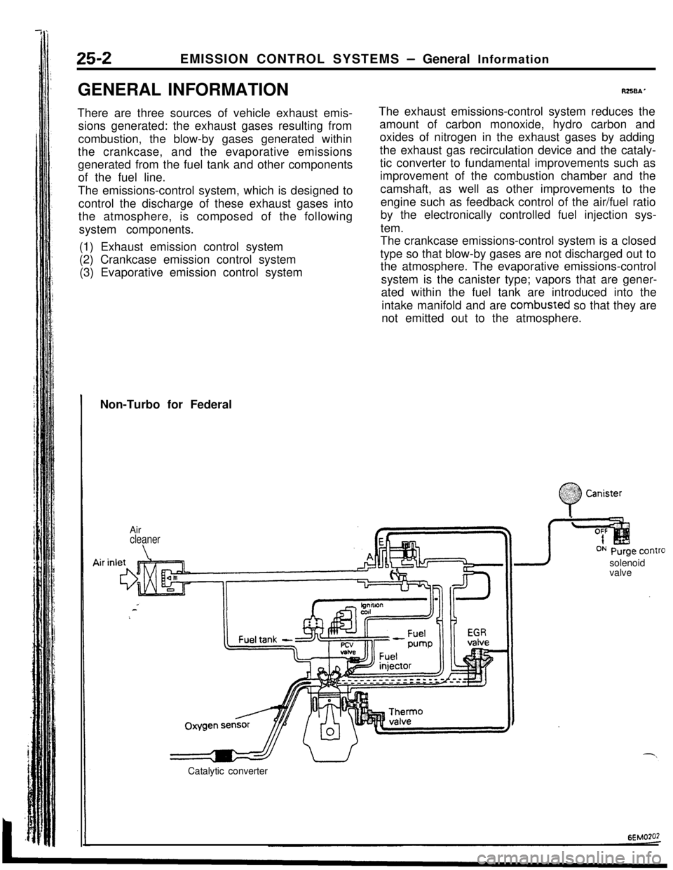
There are three sources of vehicle exhaust emis-
sions generated: the exhaust gases resulting from
combustion, the blow-by gases generated within
the crankcase, and the evaporative emissions
generated from the fuel tank and other components
of the fuel line.
The emissions-control system, which is designed to
control the discharge of these exhaust gases into
the atmosphere, is composed of the following
system components.
(1) Exhaust emission control system
(2) Crankcase emission control system
(3) Evaporative emission control system
R258A’The exhaust emissions-control system reduces the
amount of carbon monoxide, hydro carbon and
oxides of nitrogen in the exhaust gases by adding
the exhaust gas recirculation device and the cataly-
tic converter to fundamental improvements such as
improvement of the combustion chamber and the
camshaft, as well as other improvements to the
engine such as feedback control of the air/fuel ratio
by the electronically controlled fuel injection sys-
tem.
The crankcase emissions-control system is a closed
type so that blow-by gases are not discharged out to
the atmosphere. The evaporative emissions-control
system is the canister type; vapors that are gener-
ated within the fuel tank are introduced into the
intake manifold and are combusted so that they are
not emitted out to the atmosphere.
Non-Turbo for Federal
Air
cleaner
\solenoid
valve
Catalytic converter
:
0
$2:) Canister:.:
Page 376 of 391
--.
25-2EMISSION CONTROL SYSTEMS - General Information
GENERAL INFORMATION
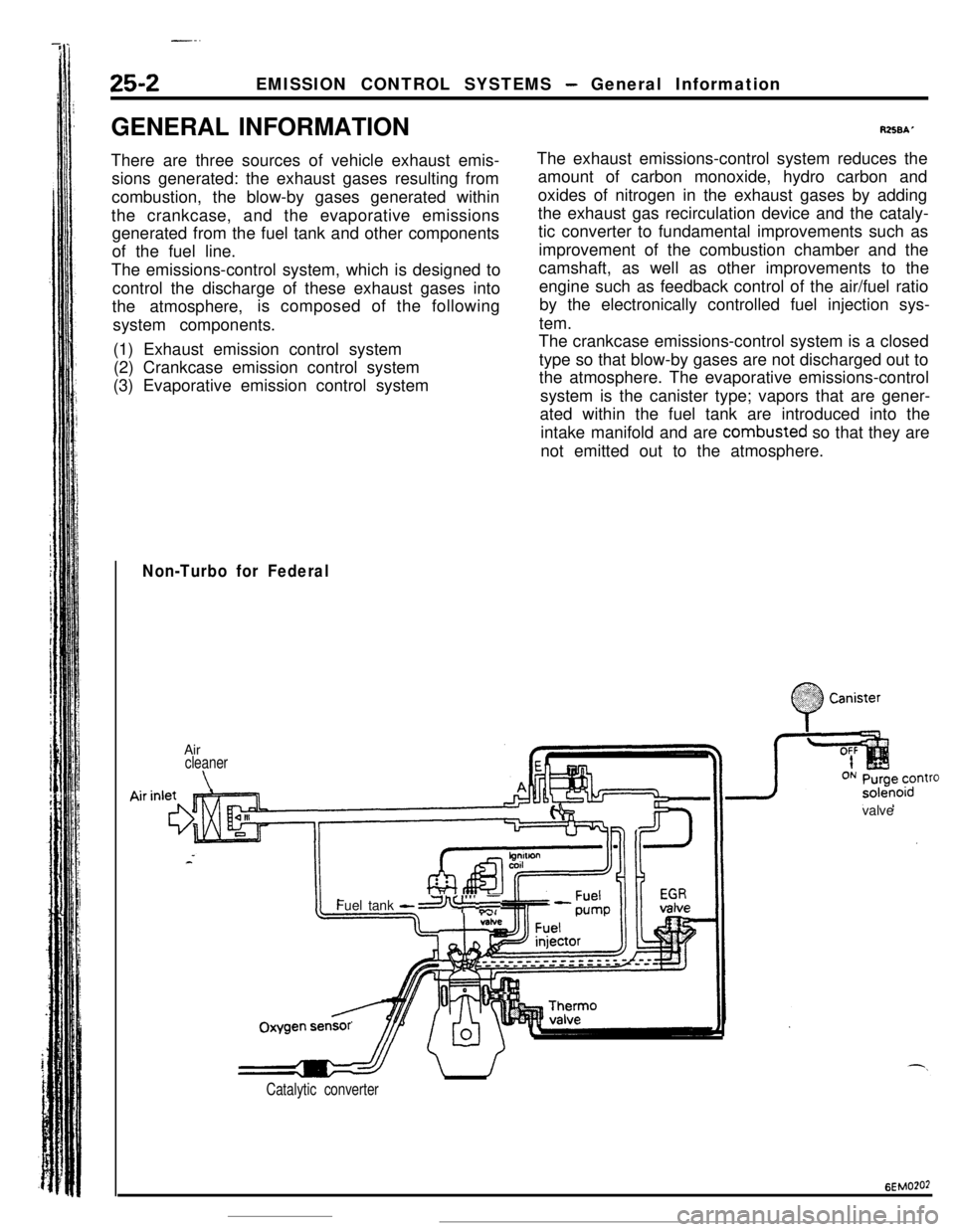
There are three sources of vehicle exhaust emis-
sions generated: the exhaust gases resulting from
combustion, the blow-by gases generated within
the crankcase, and the evaporative emissions
generated from the fuel tank and other components
of the fuel line.
The emissions-control system, which is designed to
control the discharge of these exhaust gases into
the atmosphere,is composed of the following
system components.
(1) Exhaust emission control system
(2) Crankcase emission control system
(3) Evaporative emission control system
RZSBAThe exhaust emissions-control system reduces the
amount of carbon monoxide, hydro carbon and
oxides of nitrogen in the exhaust gases by adding
the exhaust gas recirculation device and the cataly-
tic converter to fundamental improvements such as
improvement of the combustion chamber and the
camshaft, as well as other improvements to the
engine such as feedback control of the air/fuel ratio
by the electronically controlled fuel injection sys-
tem.
The crankcase emissions-control system is a closed
type so that blow-by gases are not discharged out to
the atmosphere. The evaporative emissions-control
system is the canister type; vapors that are gener-
ated within the fuel tank are introduced into the
intake manifold and are combusted so that they are
not emitted out to the atmosphere.
Non-Turbo for Federal
.;. :
0
.%??? CanisterAir
cleaner
\valveOxygenFuel tank
-a I”’ ,T
sensr’
Catalytic converter
6EMO?O2
Page 383 of 391
---- .~ _ _EMISSION CONTROL SYSTEMS
- Catalytic Converter I Air-fuel Mixture Ratio Control System25-9
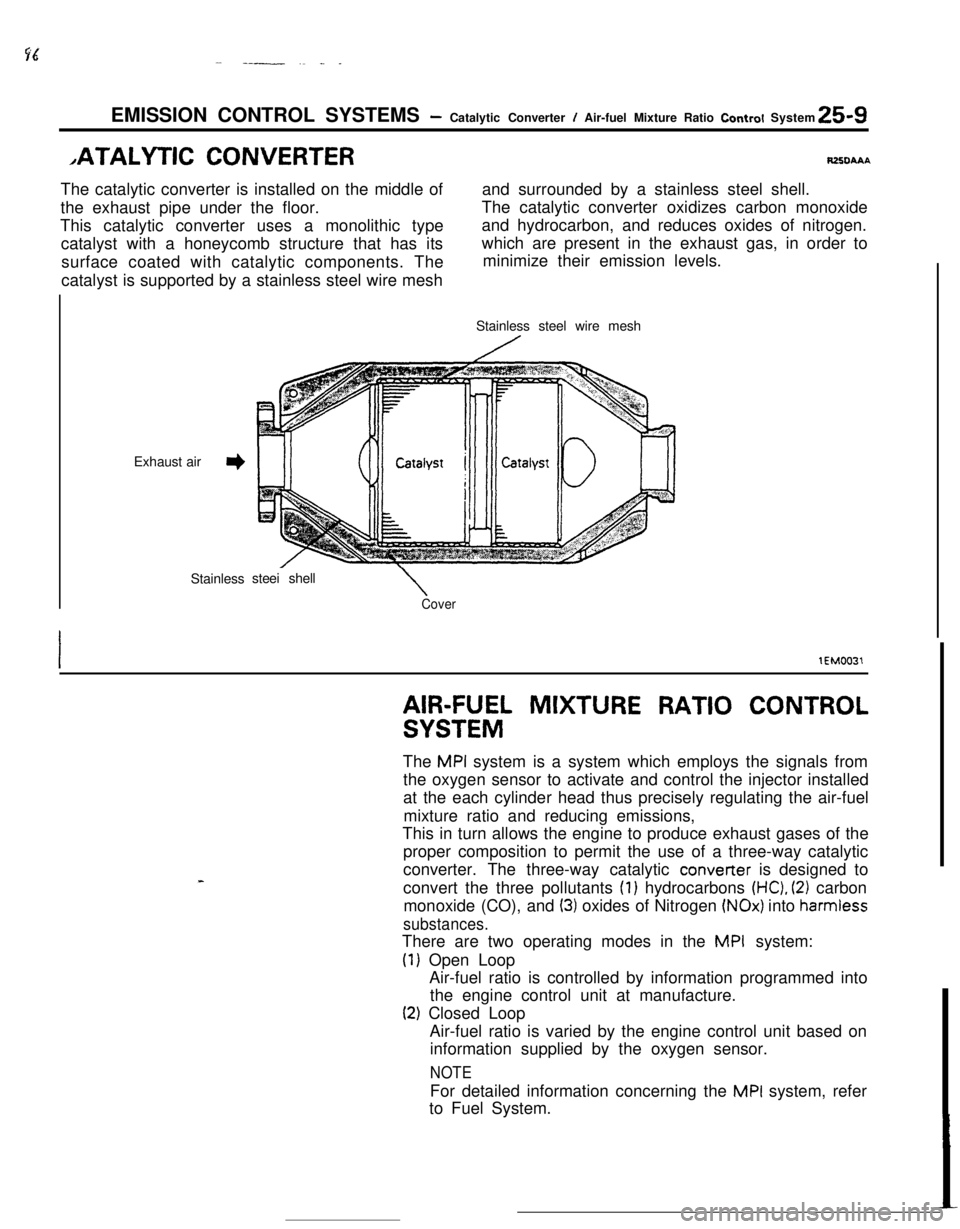
,ATALYTlC CONVERTERRZXIAAAThe catalytic converter is installed on the middle ofand surrounded by a stainless steel shell.
the exhaust pipe under the floor.The catalytic converter oxidizes carbon monoxide
This catalytic converter uses a monolithic type
catalyst with a honeycomb structure that has itsand hydrocarbon, and reduces oxides of nitrogen.
surface coated with catalytic components. Thewhich are present in the exhaust gas, in order to
minimize their emission levels.
catalyst is supported by a stainless steel wire mesh
Exhaust air
3Stainlesssteei shell
\CoverStainless steel wire mesh
lEM0031
AIR-FUEL MIXTURE RATIO CONTROL
SYSTEMThe
MPI system is a system which employs the signals from
the oxygen sensor to activate and control the injector installed
at the each cylinder head thus precisely regulating the air-fuel
mixture ratio and reducing emissions,
This in turn allows the engine to produce exhaust gases of the
proper composition to permit the use of a three-way catalytic
converter. The three-way catalytic converter is designed to
convert the three pollutants
(1) hydrocarbons (HC), (2) carbon
monoxide (CO), and
(3) oxides of Nitrogen (NOx) into harmiess
substances.There are two operating modes in the
MPI system:
(1) Open Loop
Air-fuel ratio is controlled by information programmed into
the engine control unit at manufacture.
(2) Closed Loop
Air-fuel ratio is varied by the engine control unit based on
information supplied by the oxygen sensor.
NOTEFor detailed information concerning the
MPI system, refer
to Fuel System.