belt MITSUBISHI ECLIPSE 1990 Owner's Manual
[x] Cancel search | Manufacturer: MITSUBISHI, Model Year: 1990, Model line: ECLIPSE, Model: MITSUBISHI ECLIPSE 1990Pages: 391, PDF Size: 15.27 MB
Page 348 of 391
BODY - Seat Belts
._-- -
23-31
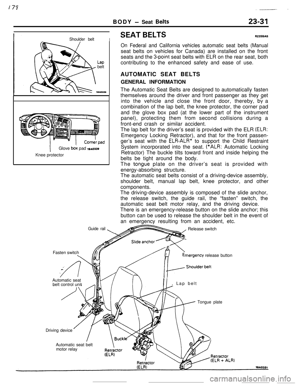
Shoulder beltI
Lapbelt
IGlove box pad toasty
Knee protector
Guide rail\Fasten switch
\
SEAT BELTSRZ3SBAS
On Federal and California vehicles automatic seat belts (Manualseat belts on vehicles for Canada) are installed on the front
seats and the
3-point seat belts with ELR on the rear seat, both
contributing to the enhanced safety and ease of use.
AUTOMATIC SEAT BELTS
GENERAL INFORMATION
The Automatic Seat Belts are designed to automatically fasten
themselves around the driver and front passenger as they get
into the vehicle and close the front door, thereby,
by a
combination of the lap belt, the knee protector, the corner pad
and the glove box pad (at the lower part of the instrument
panel), protecting them from second collisions during a
front-end crash or similar accident.
The lap belt for the driver’s seat is provided with the ELR
(ELR:Emergency Locking Retractor), and that for the front passen-
ger’s seat with the
ELR-ALR” to support the Child Restraint
System incorporated into the seat. (“ALR: Automatic Locking
Retractor) The buckle tilts toward front and inside helping the
belts be tight around the body.
The
tongue plate on the driver’s seat is provided with
energy-absorbing structure.
The automatic seat belts consist of a driving-device assembly,
shoulder belt, manual lap belt, knee protector, and other
components.
The driving-device assembly is composed of the slide anchor,
the release switch, the guide rail, the “fasten” switch, the
automatic seat belt motor relay, and the driving device.
There is an emergency-release button on the slide anchor; this
button can be used to release the shoulder belt in the event of
an emergency resulting from an accident, etc.
Release switchmergency
release button
Automatic seat
belt control unit
PI, Lap belt
Tongue plateDriving device
Automatic seat belt
motor relay
Page 349 of 391
23-32BODY - Seat Belts
OPERATION OF AUTOMATIC SEAT BELTS
The operation of the Automatic Seat Belts is as follows.
(1) The belts fasten itself around the occupant when the front
door is closed with the ignition switch in the “ON” position.
(2) The belts release itself from the occupant when the front
door is opened with the ignition switch in the
*“ON” or
“LOCK” or “ACC” position.
(3) The belts cease to fasten itself around the occupant if the
ignition switch is turned to “LOCK” or “ACC” or when the
front door is opened during the belt motion.
(4) The belts for the driver’s and front passenger’s seats
operate independently of each other.
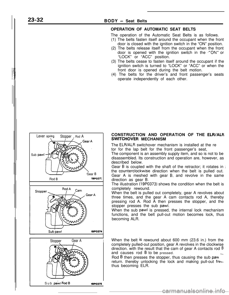
Lever springStopper, Rod A
Sub paw1
Gear B
Rod B19po37:
Sub’pawlIWO374
IStopperGear AI
ISub pai.4 dodB1980376CONSTRUCTION AND OPERATION OF THE
ELR/ALR,
SWITCHOVER MECHANISM
The
ELR/ALR switchover mechanism is installed at the re
tor for the lap belt for the front passenger’s seat,
The component is an assembly supply item, and so is not to be
disassembled. Its construction and operation are, however, as
described below.
Gear
B is coupled with the shaft of the retractor; it rotates in ::the counterclockwise direction when the belt is pulled out.
Gear A is meshed with gear
B, and revolve in the same
direction as gear
B.The illustration
(19PO373) shows the condition when the belt is
completely rewound.
When the belt is pulled out completely, gear A revolves about
three times, and the gear A cam contacts rod A, thereby
pressing rod A. Rod A then presses the stopper, and the
stopper presses the sub
pawl.When the sub pawl is pressed, the internal lock mechanism
functions, and the belt pull-out motion becomes lock, thus
becoming ALR.
When the belt
is rewound about 600 mm (23.6 in.) from the
completely pulled-out position, gear A revolves in the clockwise
direction. with the result that the cam of gear A contacts rod
6and causes rod
B to be pressed.
Rod
B then presses the stopper, thus causing the sub pan -return. thereby unlocking the lock and making pull-out
freti.thus becoming ELR.
Page 350 of 391
BODY - Seat Belts23-33
Gear eGear B
Energy-absorbingbelt
Before absorbing
shock
19AO332Inward
Forward
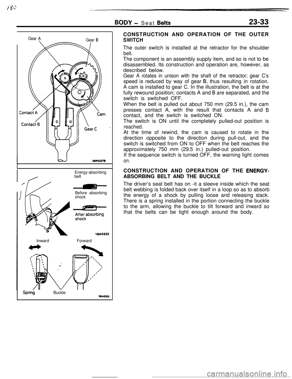
Sprin$BuckleCONSTRUCTION AND OPERATION OF THE OUTER
SWITCHThe outer switch is installed at the retractor for the shoulder
belt.The component is an assembly supply item, and so is not to be
disassembled. Its construction and operation are, however, as
described below.
Gear A rotates in unison with the shaft of the retractor; gear C’sspeed is reduced by way of gear
B, thus resulting in rotation.
A cam is installed to gear C. In the illustration, the belt is at the
fully rewound position; contacts A and
B are separated, and the
switch is switched OFF.
When the belt is pulled out about 750 mm (29.5 in.), the cam
presses contact A, with the result that contacts A and
Bcontact, and the switch is switched ON.
The switch is ON until the completely pulled-out position is
reached.At the time of rewind, the cam is caused to rotate in the
direction opposite to the direction during pull-out, and the
switch is switched from ON to OFF when the belt reaches the
approximately 750 mm (29.5 in.) pulled-out position.
If the sequence switch is turned OFF, the warning light comes
on.CONSTRUCTION AND OPERATION OF THE
ENERGY-ABSORBING BELT AND THE BUCKLE
The driver’s seat belt has on -it a sleeve inside which the seat
belt webbing is folded back over itself in a loop so as to absorb
the energy of a shock by pulling loose and releasing slack.
There is a spring installed in the portion connecting the buckle
to the arm, allowing the buckle to tilt forward and inward so
that the belts can be tight enough around the body.
Page 351 of 391
23-34BODY - Seat Belts
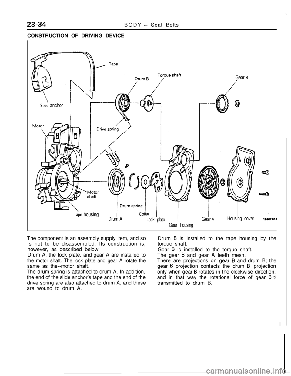
CONSTRUCTION OF DRIVING DEVICE
Slid& anchor
Tabe housingIColiar 1
Drum ALock plate
Gear housing
Gear B
Gear AHousing cover
I
lOPO288The component is an assembly supply item, and so
is not to be disassembled. Its construction is,
however, as described below.
Drum A, the lock plate, and gear A are installed to
the motor shaft. The lock plate and gear A rotate thesame as the--motor shaft.
The drum
&ring is attached to drum A. In addition,
the end of the slide anchor’s tape and the end of the
drive spring are also attached to drum A, and these
are wound to drum A.Drum
B is installed to the tape housing by the
torque shaft.
Gear
B is installed to the torque shaft.
The gear
B and gear A teeth mesh.
There are projections on gear
B and drum B; the
gear
B projection contacts the drum B projection
only when gear
B rotates in the clockwise direction.
and in that way the rotational force of gear
B istransmitted to drum B.
I
Page 352 of 391
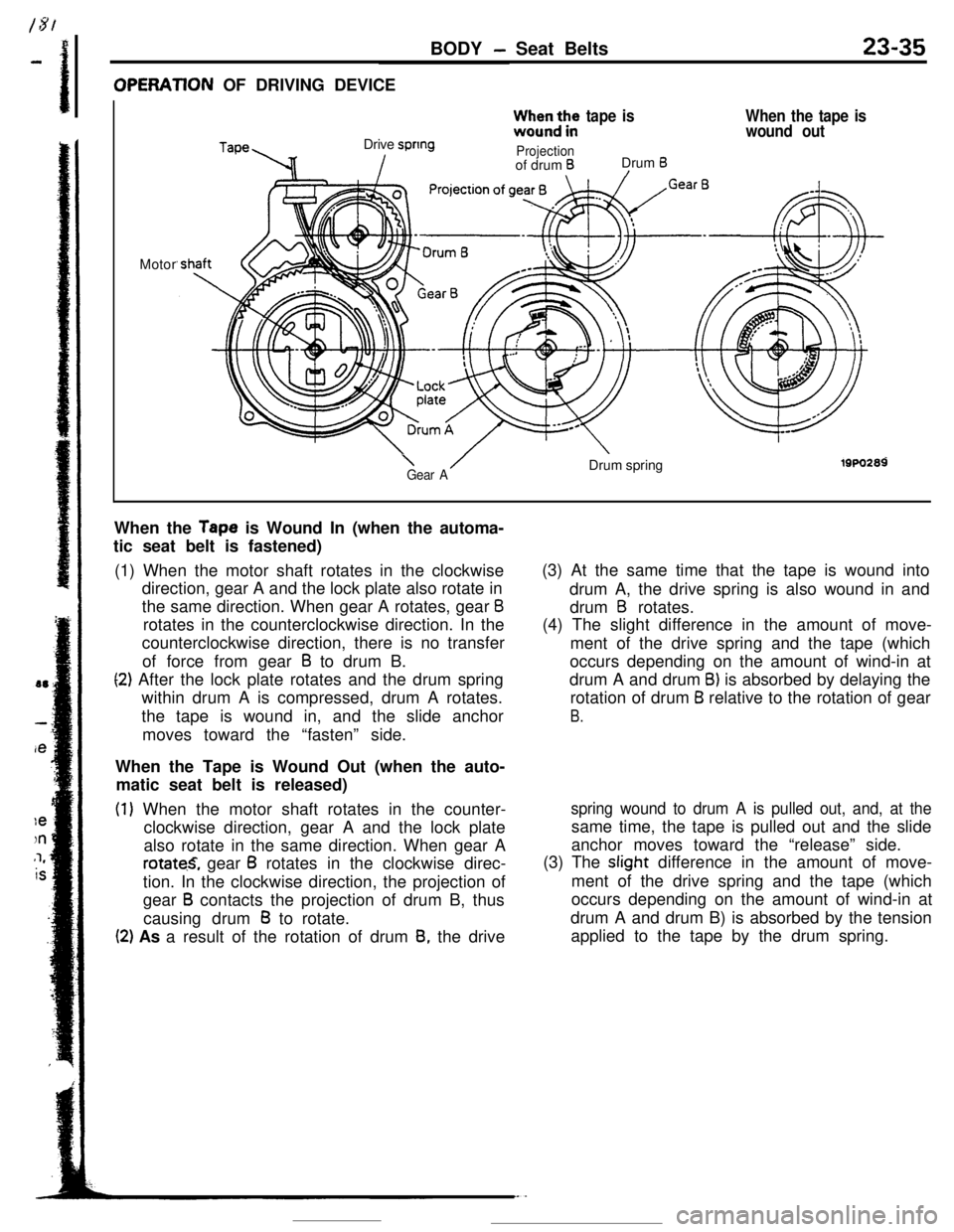
BODY - Seat Belts23-35OPERATlON OF DRIVING DEVICE
TapeDrive spring
Izz;b3;:,e
tape is
Projectionof drum BDrum B/
When the tape is
wound outMotor
\ /Gear ADrum springi9w2a9When the
Tape is Wound In (when the automa-
tic seat belt is fastened)
(1) When the motor shaft rotates in the clockwise
direction, gear A and the lock plate also rotate in
the same direction. When gear A rotates, gear
Brotates in the counterclockwise direction. In the
counterclockwise direction, there is no transfer
of force from gear
B to drum B.
(2) After the lock plate rotates and the drum spring
within drum A is compressed, drum A rotates.
the tape is wound in, and the slide anchor
moves toward the “fasten” side.
When the Tape is Wound Out (when the auto-
matic seat belt is released)
(1) When the motor shaft rotates in the counter-
clockwise direction, gear A and the lock plate
also rotate in the same direction. When gear A
rotate.S, gear B rotates in the clockwise direc-
tion. In the clockwise direction, the projection of
gear
B contacts the projection of drum B, thus
causing drum
B to rotate.
(2) As a result of the rotation of drum 8, the drive(3) At the same time that the tape is wound into
drum A, the drive spring is also wound in and
drum
B rotates.
(4) The slight difference in the amount of move-
ment of the drive spring and the tape (which
occurs depending on the amount of wind-in at
drum A and drum
B) is absorbed by delaying the
rotation of drum
B relative to the rotation of gear
B.
spring wound to drum A is pulled out, and, at thesame time, the tape is pulled out and the slide
anchor moves toward the “release” side.
(3) The slight difference in the amount of move-
ment of the drive spring and the tape (which
occurs depending on the amount of wind-in at
drum A and drum B) is absorbed by the tension
applied to the tape by the drum spring.
Page 353 of 391
23-36BODY -Seat Belts
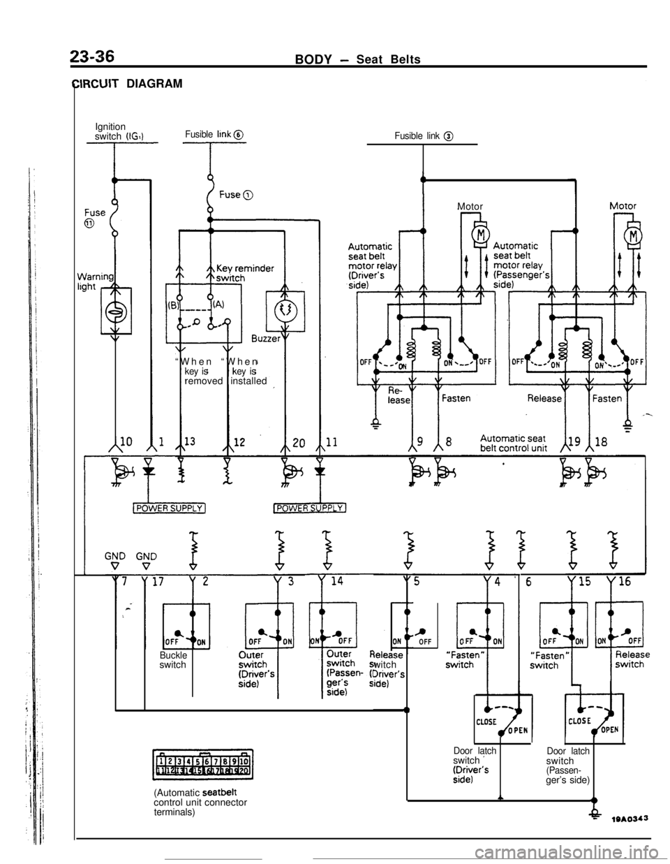
IRCUIT DIAGRAM
Ignition
switch
(IGIlFusible llnk @
-T- --T-
A10“When “When
key iskey isremoved installed
Fusible link @
Buckleswitch
(Automatic seatbelt
control unit connector
terminals)leiease
witch
?r$r’s
0Motor
c,OFF
6
Door latchswitch ’fDr:r’s
Door latchswitch
(Passen-ger’s side)
A?
-f&19*0343
Page 354 of 391
BODY - Seat Belts23-37COMPONENT PARTS AND FUNCTION
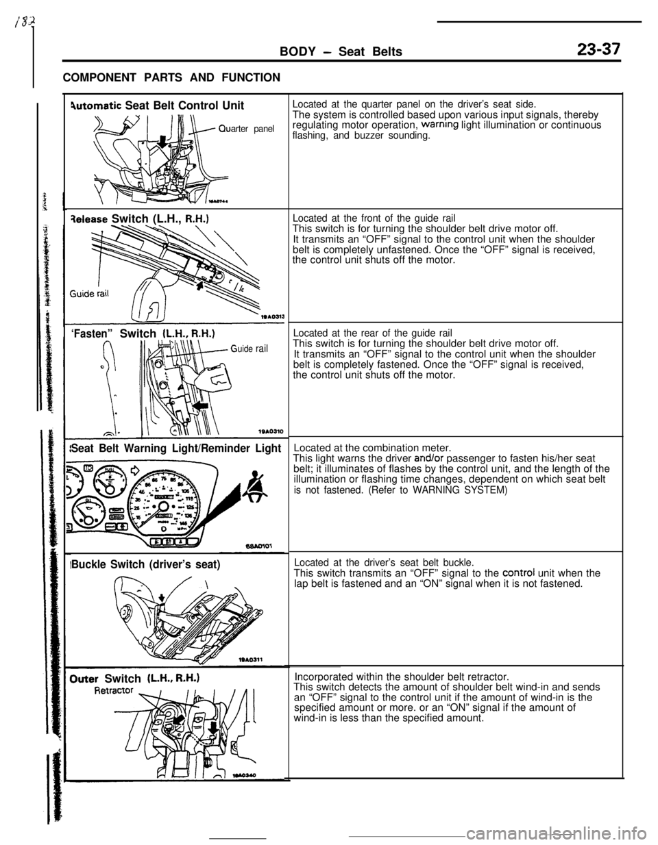
4utomatic Seat Belt Control Unit
arter panel
qelease Switch (L.H., R.H.)
‘Fasten”Switch (L.H., R.H.)
uide rail
1SAO310
Seat Belt Warning Light/Reminder Light
Buckle Switch (driver’s seat)
Outer Switch (LH., R.H.)
Located at the quarter panel on the driver’s seat side.The system is controlled based upon various input signals, thereby
regulating motor operation,
warnrng light illumination or continuousflashing, and buzzer sounding.
Located at the front of the guide railThis switch is for turning the shoulder belt drive motor off.
It transmits an “OFF” signal to the control unit when the shoulder
belt is completely unfastened. Once the “OFF” signal is received,
the control unit shuts off the motor.
Located at the rear of the guide railThis switch is for turning the shoulder belt drive motor off.
It transmits an “OFF” signal to the control unit when the shoulder
belt is completely fastened. Once the “OFF” signal is received,
the control unit shuts off the motor.
Located at the combination meter.
This light warns the driver
and/or passenger to fasten his/her seat
belt; it illuminates of flashes by the control unit, and the length of the
illumination or flashing time changes, dependent on which seat belt
is not fastened. (Refer to WARNING SYSTEM)
Located at the driver’s seat belt buckle.This switch transmits an “OFF” signal to the
control unit when the
lap belt is fastened and an “ON” signal when it is not fastened.
Incorporated within the shoulder belt retractor.
This switch detects the amount of shoulder belt wind-in and sends
an “OFF” signal to the control unit if the amount of wind-in is the
specified amount or more. or an “ON” signal if the amount of
wind-in is less than the specified amount.
Page 355 of 391
23-38BODY - Seat Belts
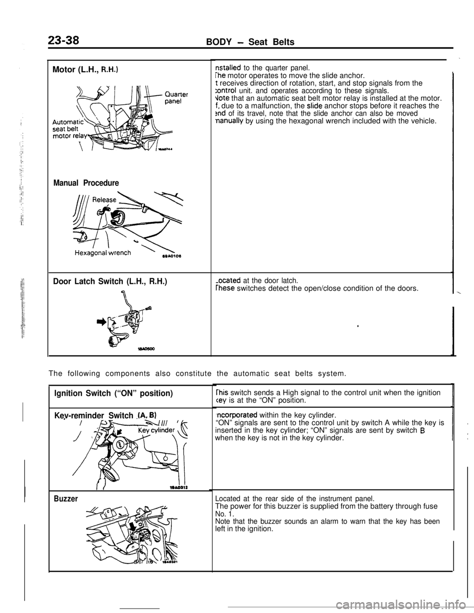
Motor (L.H.,
R.H.)
Manual Procedure
Door Latch Switch (L.H., R.H.)
7
nstalled to the quarter panel.
The motor operates to move the slide anchor.t receives direction of rotation, start, and stop signals from the
:ontroi unit. and operates according to these signals.Jote that an automatic seat belt motor relay is installed at the motor.f. due to a malfunction, the slide anchor stops before it reaches the2nd of its travel, note that the slide anchor can also be movednanually by using the hexagonal wrench included with the vehicle.
-ocated at the door latch.
rhese switches detect the open/close condition of the doors.
The following components also constitute the automatic seat belts system.
Ignition Switch (“ON” position)
Kev-reminder Switch
(A. B)
Buzzer
rhis switch sends a High signal to the control unit when the ignition
“ON” signals are sent to the control unit by switch A while the key is
inserted in the key cylinder; “ON” signals are sent by switch
Bwhen the key is not in the key cylinder.
Located at the rear side of the instrument panel.The power for this buzzer is supplied from the battery through fuse
No. 1.
Note that the buzzer sounds an alarm to warn that the key has beenleft in the ignition.
Page 356 of 391
BODY - Seat Belts23-39
OPERATlON
Belt Fastening Motion
(1) If the belt is not in the fastening position (the
L.H. or R.H. door latch switch at Door Closed
position; the L.H. or R.H. “fasten” switch at
“ON” position) when the door is closed with the
ignition switch in the “ON” position, the belt
automatically moves to the fastening position.
For the period between the initiation and com-
pletion of the belt’s motion in the fastening
direction, the seat belt warning light either stays
lit or blinks.
Belt Releasing Motion
(1) When the belt is not in the release position, the
L.H. or R.H. release switch is in the “ON”
position, and the left or right door is opened, the
belt will automatically move to the release
position if the ignition switch is at either the
“ON”,“LOCK” or “ACC” position.
For the belt at the driver’s seat side moveover,
the belt will automatically move to the release
position if the
key is taken out while the belt is
fastened.
The buzzer sounds for approximately 0.7 secondsince the start of thebelt’s motion.When the belt is completely fastened, the
“fasten” switch is switched OFF and the motor
stops.(2) With a lapse of approximately 60 seconds after
the belt has stopped its fastening motion due to
foreign object wedged in the mechanism, the
protective timer of the control unit is activated
causing the motor output to the shut off.
When the belt completes its releasing motion,
the L.H. or R.H. release switch is turned OFF,
and the motor stops.
(2)If the belt is still in the process of releasing with
a lapse of approximately 60 seconds after the
start of motion, the protective timer in control
unit is activated causing the motor output to be
shut off.
At the same time, the buzzer sounds for
approximately 0.7 second.
Ignitionswitch
(ONI I------(LOCK or ACC) -J
Warning
light
I-6 sec. ’
cWARNING SYSTEM
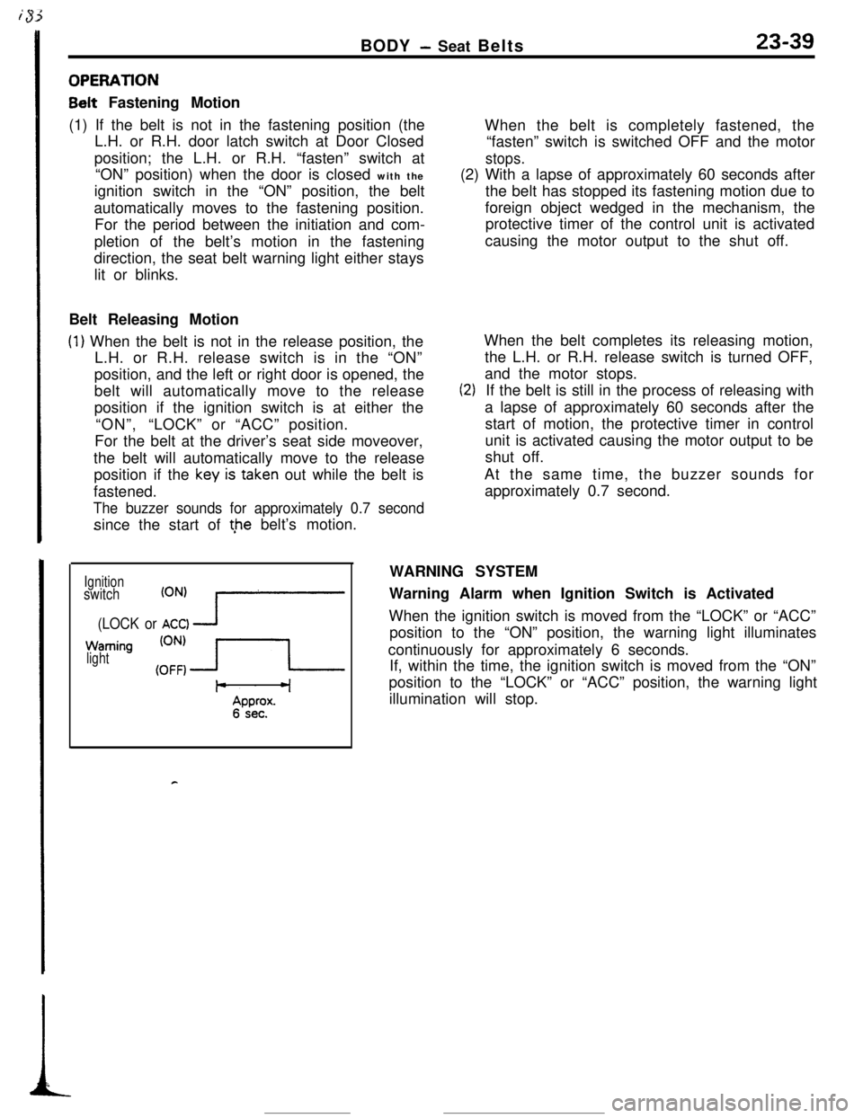
Warning Alarm when Ignition Switch is Activated
When the ignition switch is moved from the “LOCK” or “ACC”
position to the “ON” position, the warning light illuminates
continuously for approximately 6 seconds.
If, within the time, the ignition switch is moved from the “ON”
position to the “LOCK” or “ACC” position, the warning light
illumination will stop.
Page 357 of 391
23-40BODY - Seat Belts
Door latch
switch
Ignition
switch
(LOCK or
ZjTI
Warninglight
.
F-w4Approx. 6 sec.
~1: Warning alarm when ignition
switch is activated.
r2: Approx. 0.7 sec./cycle
Driver’s side
latch switch
Ignition
switch
(LOCK or
Er:rI
ti Fasten” switch
Driver’s side
(ON) i;outer switch
(OFF)I!
’ III
Buzzer(ON’
(OFF)c
Warning ’light
kprox. 66 sec.’Ignition
switch
(LOCK or zm
zs;;;$s (ON)
side outer
switch(OFFIr
Warninglight
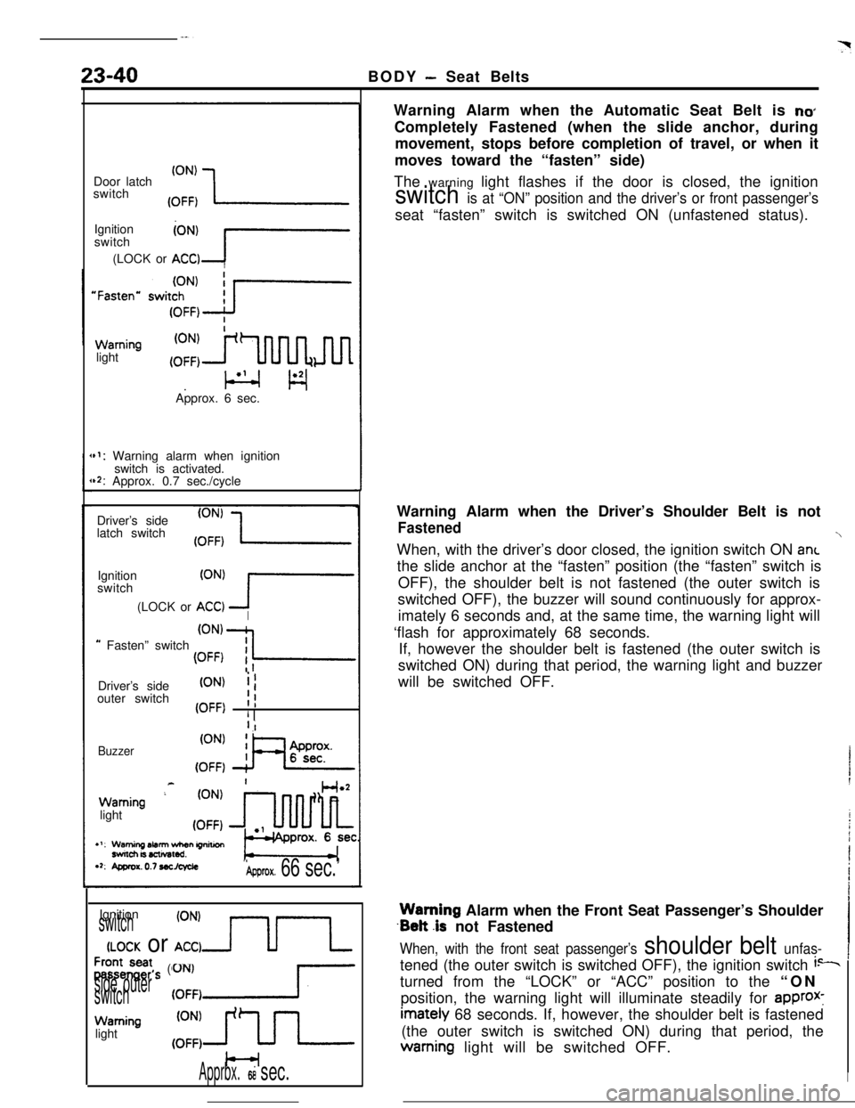
Apprbx.ti sec.Warning Alarm when the Automatic Seat Belt is
no*Completely Fastened (when the slide anchor, during
movement, stops before completion of travel, or when it
moves toward the “fasten” side)
The warning light flashes if the door is closed, the ignition
switch is at “ON” position and the driver’s or front passenger’sseat “fasten” switch is switched ON (unfastened status).
Warning Alarm when the Driver’s Shoulder Belt is not
FastenedWhen, with the driver’s door closed, the ignition switch ON ant
the slide anchor at the “fasten” position (the “fasten” switch is
OFF), the shoulder belt is not fastened (the outer switch is
switched OFF), the buzzer will sound continuously for approx-
imately 6 seconds and, at the same time, the warning light will
‘flash for approximately 68 seconds.
If, however the shoulder belt is fastened (the outer switch is
switched ON) during that period, the warning light and buzzer
will be switched OFF.Warning Alarm when the Front Seat Passenger’s Shoulder
.Belt .is not Fastened
When, with the front seat passenger’s shoulder belt unfas-tened (the outer switch is switched OFF), the ignition switch
i--turned from the “LOCK” or “ACC” position to the “ON
position, the warning light will illuminate steadily for
approx-imately 68 seconds. If, however, the shoulder belt is fastened
(the outer switch is switched ON) during that period, thewarning light will be switched OFF.
I