air condition MITSUBISHI ECLIPSE 1990 Owner's Guide
[x] Cancel search | Manufacturer: MITSUBISHI, Model Year: 1990, Model line: ECLIPSE, Model: MITSUBISHI ECLIPSE 1990Pages: 391, PDF Size: 15.27 MB
Page 274 of 391
21-50AUTOMATIC TRANSAXLE - Transaxle Control
Vehicle
sensorspeedTerminal voltage
(VI
1
5
\*Fluidtemperature
02080PCI 1750409VEHICLE-SPEED SENSOR
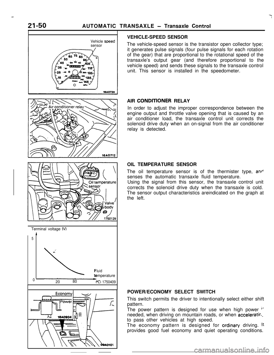
The vehicle-speed sensor is the transistor open collector type;
it generates pulse signals (four pulse signals for each rotation
of the gear) that are proportional to the rotational speed of the
transaxle’s output gear (and therefore proportional to the
vehicle speed) and sends these signals to the transaxle control
unit. This sensor is installed in the speedometer.
AIR CONDlTlONER RELAY
In order to adjust the improper correspondence between the
engine output and throttle valve opening that is caused by an
air conditioner load, the transaxle control unit corrects the
solenoid drive duty when an on-signal from the air conditioner
relay is detected.
OIL TEMPERATURE SENSOR
The oil temperature sensor is of the thermister type,
an+senses the automatic transaxle fluid temperature.
Using the signal from this sensor, the transaxle control unit
corrects the solenoid drive duty when the transaxle is cold.
The sensor output characteristics areindicated on the graph at
the left.
POWER/ECONOMY SELECT SWITCH
This switch permits the driver to intentionally select either shift
pattern.
The power pattern is designed for use when high power
‘*needed, when driving on mountain roads, or when acceleratirl,
to pass other vehicles at high speed.
The economy pattern is designed for ordinan/ driving.
ltprovides good fuel economy and quiet operating conditions.
Page 365 of 391
24-2 HEATERS AND AIR CONDITIONING
1 OPA17 swash plate t:
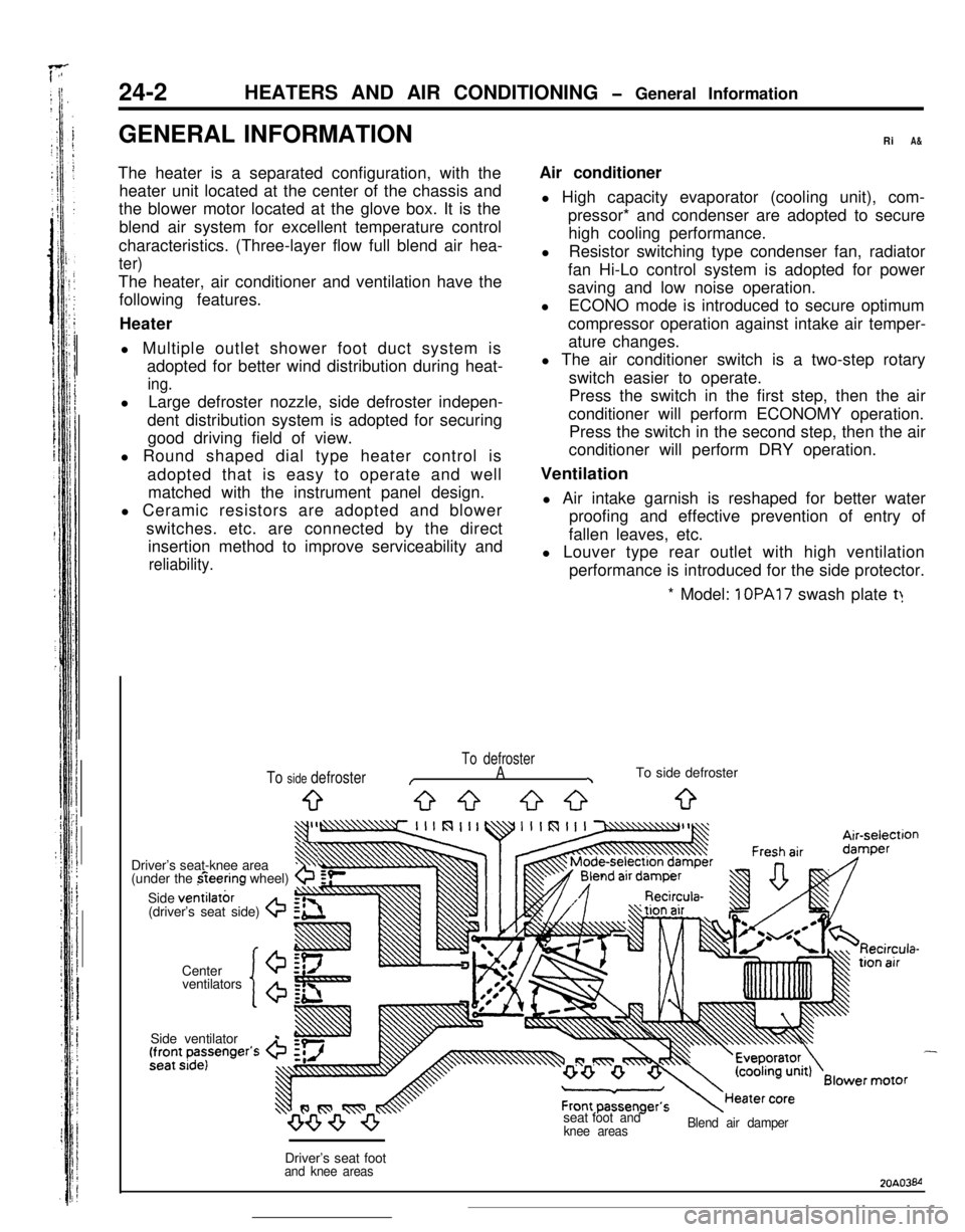
To defroster
/A\To side defroster
9G-3 53033
ventilators
‘lo’
Driver’s seat-knee area3$
(under the fieering wheel)b
Side ventilatbr(driver’s seat side) G
Center
20A03M
Page 366 of 391
_-‘5sY-HEATERS AND AIR CONDITIONING
- General Information
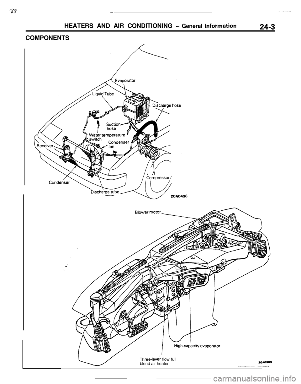
COMPONENTS24-3Three-Iaye; flow full
blend air heater
Page 367 of 391
L.
24-4HEATERS AND AIR CONDITIONING - General Information
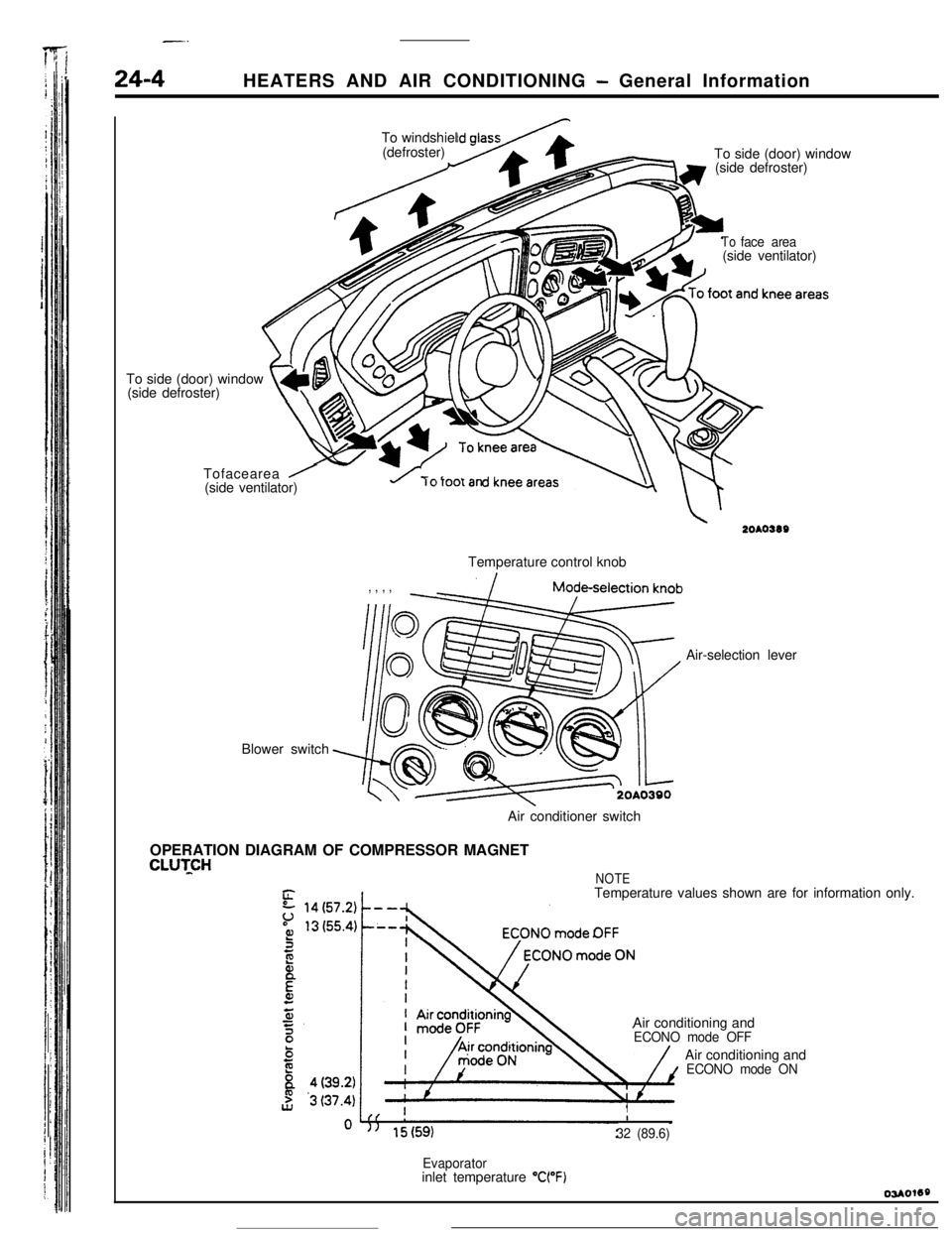
’ /To side (door) window
(side defroster)
t4L\ m\vTofacearea
/(side ventilator)To windshiel
(defroster)
To side (door) window
(side defroster)
Blower switch
Toface area(side ventilator)
u rorootanTemperature control knob
, , , ,Air-selection lever
Air conditioner switch
OPERATION DIAGRAM OF COMPRESSOR MAGNET
CLUTCHNOTETemperature values shown are for information only.
Air conditioning and
ECONO mode OFFAir conditioning and
ECONO mode ON
II
32 (89.6)
Evaporatorinlet temperature “WF)
Page 368 of 391
HEATERS AND AIR CONDITIONING- General information I Heater Construction24-5
16AO611
Section A-A
Air intake garnish
Check
Section B-B
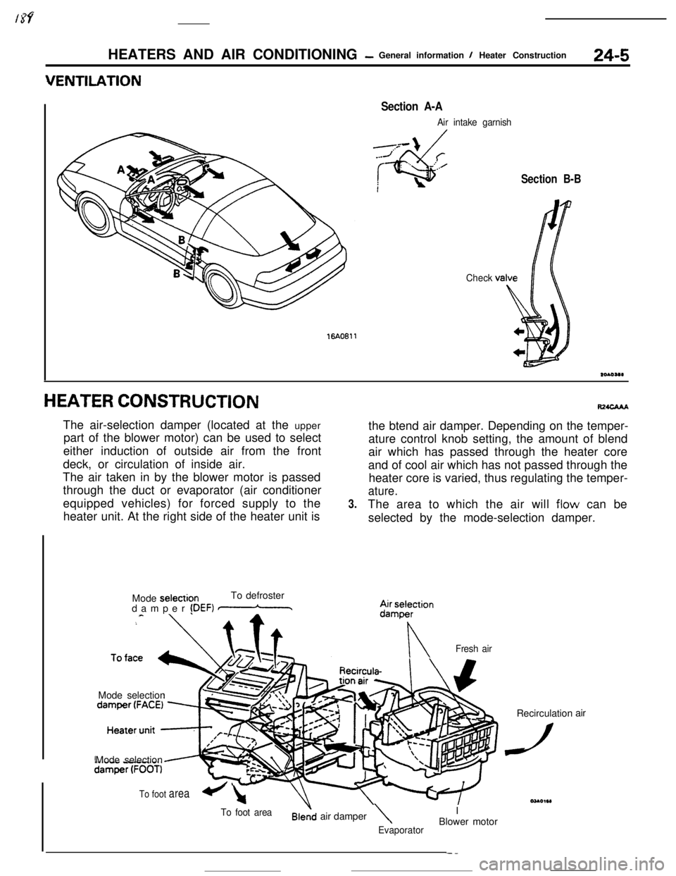
HEATER CONSTRUCTIONThe air-selection damper (located at the upper
part of the blower motor) can be used to select
either induction of outside air from the front
deck, or circulation of inside air.
The air taken in by the blower motor is passed
through the duct or evaporator (air conditioner
equipped vehicles) for forced supply to the
heater unit. At the right side of the heater unit is
Mode selectionTo defroster
damper
!DEF) mMode selection
3.the btend air damper. Depending on the temper-
ature control knob setting, the amount of blend#waAA
air which has passed through the heater core
and of cool air which has not passed through the
heater core is varied, thus regulating the temper-
ature.The area to which the air will
flow can be
selected by the mode-selection damper.
nFresh airMode selection
To foot areaair damper\IEvaporatorBlower motorRecirculation
dair
To foot area+-l
Page 369 of 391
--
24-6HEATERS AND AIR CONDITIONING - Heater Construction
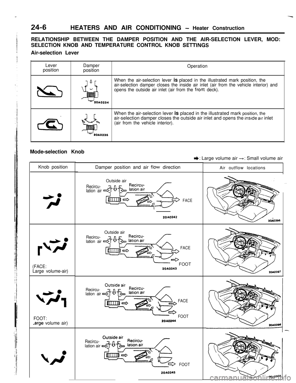
RELATIONSHIP BETWEEN THE DAMPER POSITION AND THE AIR-SELECTION LEVER, MOD:
SELECTION KNOB AND TEMPERATURE CONTROL KNOB
SETlINt%Air-selection Lever
LeverpositionDamperpositionOperation
When the air-selection lever
is placed in the illustrated mark position, the
air-selection damper closes the inside air inlet (air from the vehicle interior) and
opens the outside air inlet (air from the from
deck).When the air-selection lever is placed in the illustrated mark position, the
air-selection damper closes the outside air inlet and opens the
inslde atr inlet
(air from the vehicle interior).Mode-selection Knob
Knob position
(FACE:Large volume-air)
FOOT:-arge volume air)Damper position and air
flow direction
Recircu-
lation airOutside air
FACE
I): Large volume air --t: Small volume air
20A0242
Recircu-
lation airOutside air
FACE
-- FOOT2040243
Recircu-
lation air
FACE
FOOT
Recircu-lation air
FOOT
20A0245Air outflow locations
Page 370 of 391

HEATERS AND AIR CONDITIONING - Heater Construction24-7
IKnob posltionDamper position and air flow direction
Air outflow locations
Outside air
Recircu-lation air
2010246
Recircu-iation airDEF
2OAO247Temperature Control Knob
IKnob positionDamper position and air ‘flow directionOperation
When the temperature control knob or
the heater control is rotated fully
counterclockwise toward the cool air
position, the upper side of the heater
core will be blocked up by the blend
air damper A. whereas the lower side
of the heater core
will be blocked up by
the blend air damper 8. As a result.
all the air from the blower motor does
not pass through the heater core but
directly flows out as cool air.
Blend air damper CBlend air damper A
x!= cY?l-nY-/
-1 From
To air Voutflowopenings*blower
motor
Hester ‘OreOUO,,O
Blend air damper CBlend air damper A,//7When the temperature control knob of
the heater control is rotated fully
ctockwise toward the warm air position.the blend air dampers A and Bwill block the cool air paths.
The cool air from the blower motor
passes through the heater core for
maximum heating..
Tooutflow
openings
Blend al’r damper B
When the temperature control knob of
the heater control is rotated to the
mid position, the blend air dampers A
and B will split the air stream intotwo branches, one passing through the
heater core and one not passing through
the heater core. The blend damper air
Cintroduces cool air from the heater core
top into the heater unit chamber. Air
conditioning is provided by mixing this
cool air with hot air heated by the
heater cores.
Blend air damper CBlend/ air damper AL
2OAO391Blend air damoer B
--.-__.__ ,_ .
Page 371 of 391
-.-- ----_-
24-8HEATERS AND AIR CONDITIONING - Compressor
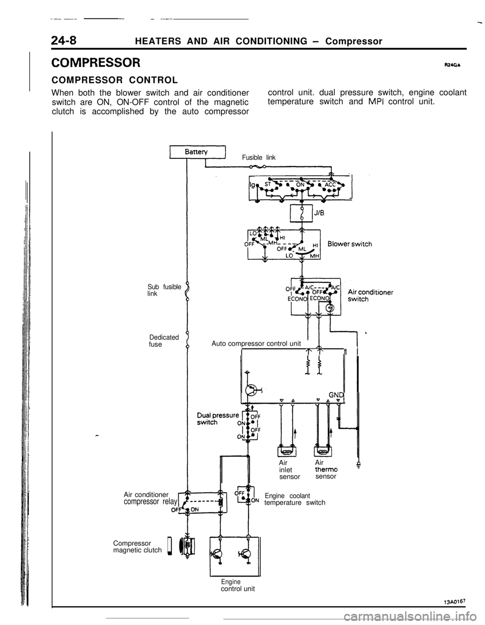
COMPRESSORR24GbCOMPRESSOR CONTROL
When both the blower switch and air conditioner
switch are ON, ON-OFF control of the magnetic
clutch is accomplished by the auto compressorcontrol unit. dual pressure switch, engine coolant
temperature switch and
MPI control unit.
Sub fusible
link
Dedicatedfuse
Air conditioner
compressor relayrOFfCompressor
magnetic clutch
q l
Fusible link
lgnitionsyhWqb 1Auto compressor control unit
ITT1 I
0 bIAirAir
inlettherm0
4sensorsensor
Engine coolanttemperature switch
Enginecontrol unit13A0167
Page 372 of 391
19/---..-_HEATERS AND AIR CONDITIONING
- Idle Speed Control24-9
Ii” E SPEED CONTROL
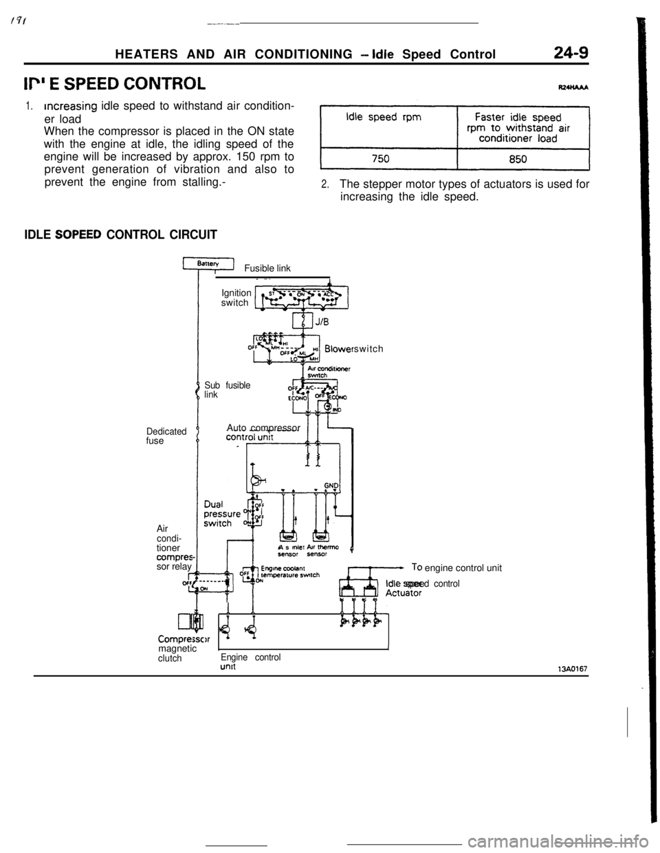
1.increasing idle speed to withstand air condition-
er load
When the compressor is placed in the ON state
with the engine at idle, the idling speed of the
engine will be increased by approx. 150 rpm to
prevent generation of vibration and also to
prevent the engine from stalling.-
2.The stepper motor types of actuators is used for
increasing the idle speed.
IDLE SOPEED CONTROL CIRCUITFusible link
Dedicatedfuse
Air
condi-tioner
compressor relay
I-gcfc
Lll
Compre:Ignition
switch
Sub fusible
linkswitch
Auto compressor
As
mlef kr Ihemo
Ax;,: engine control unit
Idle speed control
Y *e:Q
1
$4.1111.Pk+F)rmagneticIJ
clutchEngine controlunit13AO167
Page 380 of 391
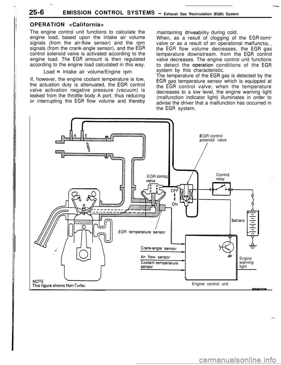
-.-
25-6EMISSION CONTROL SYSTEMS- Exhaust Gas Recirculation (EGR) System
OPERATION
The engine control unit functions to calculate the
engine load, based upon the intake air volume
signals (from the air-flow sensor) and the rpm
signals (from the crank-angle sensor), and the
EGRcontrol solenoid valve is activated according to the
engine load. The
EGR amount is then regulated
according to the engine load calculated in this way.maintaining driveability during cold.
When, as a result of clogging of the
EGR cant’valve or as a result of an operational
malfunctio,.,the
EGR flow volume decreases, the EGR gas
temperature downstream. from the
EGR control
valve decreases. The engine control unit functions
to detect the
operation conditions of the EGRLoad
a Intake air volume/Engine rpmsystem by this characteristic.
If, however, the engine coolant temperature is low,
the actuation duty is attenuated, the
EGR control
valve activation negative pressure (vacuum) is
leaked from the throttle body A port, thus reducing
or interrupting the
EGR flow volume and therebyThe temperature of the
EGR gas is detected by the
EGR gas temperature sensor which is equipped at
the
EGR control valve; when the temperature
decreases to a low level, the engine warning light
(malfunction indicator light) illuminates in order to
advise the driver that a malfunction has occurred in
the
EGR system.
EGR
contcEGR control
solenoid valve
/Control
relay
1Engine control unit
Enginewarning
light