air condition MITSUBISHI ECLIPSE 1990 User Guide
[x] Cancel search | Manufacturer: MITSUBISHI, Model Year: 1990, Model line: ECLIPSE, Model: MITSUBISHI ECLIPSE 1990Pages: 391, PDF Size: 15.27 MB
Page 115 of 391
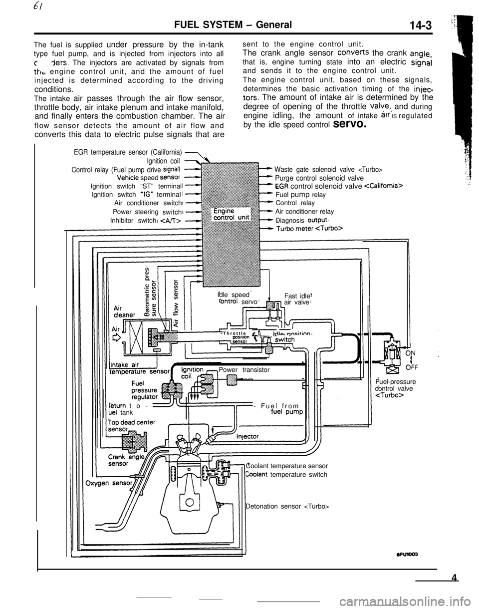
FUEL SYSTEM - General14-3The fuel is supplied under pressure by the in-tanksent to the engine control unit.
type fuel pump, and is injected from injectors into allThe crank angle sensor converts the crank
angle,
cders. The injectors are activated by signals fromthat is, engine turning state into an electric signal
tk, engine control unit, and the amount of fueland sends it to the engine control unit.
injected is determined according to the drivingThe engine control unit, based on these signals,
conditions.determines the basic activation timing of the
injec-The intake air passes through the air flow sensor,
tars. The amount of intake air is determined by the
throttle body, air intake plenum and intake manifold,degree of opening of the throttle
valye,, and during
and finally enters the combustion chamber. The airengine idling, the amount of intake
arr IS regulated
flow sensor detects the amount of air flow and
by the idle speed control servo.converts this data to electric pulse signals that are
EGR temperature sensor (California) 7
Waste gate solenoid valve
Purge control solenoid valve
EGR control solenoid valve
Control relay
Air conditioner relay
Diagnosis output
Ignition coil
Control relay (Fuel pump drive
signal)Vehicle speed
SensorIgnition switch “ST” terminal
Ignition switch
‘IG” terminal
Air conditioner switch
Power steering
switch
Inhibitor switch
Idle speed
ontrol servoFast idle
air valve
-Throttle
&r -kilo m-i&inn’Power transistorleturn to-
uel tank- Fuel from
Coolant temperature sensor
Coolant temperature switchFuel-pressure
control valve
4
Page 123 of 391
FUEL SYSTEM -Fuel Supply and Fuel Pressure Control
FUEL-PRESSURE CONTROL VALVE
14-11To fuel
-
Fuel-pressureregulatorFuel-pressurecontrol valve
Intake-airEnginecontrol
unit
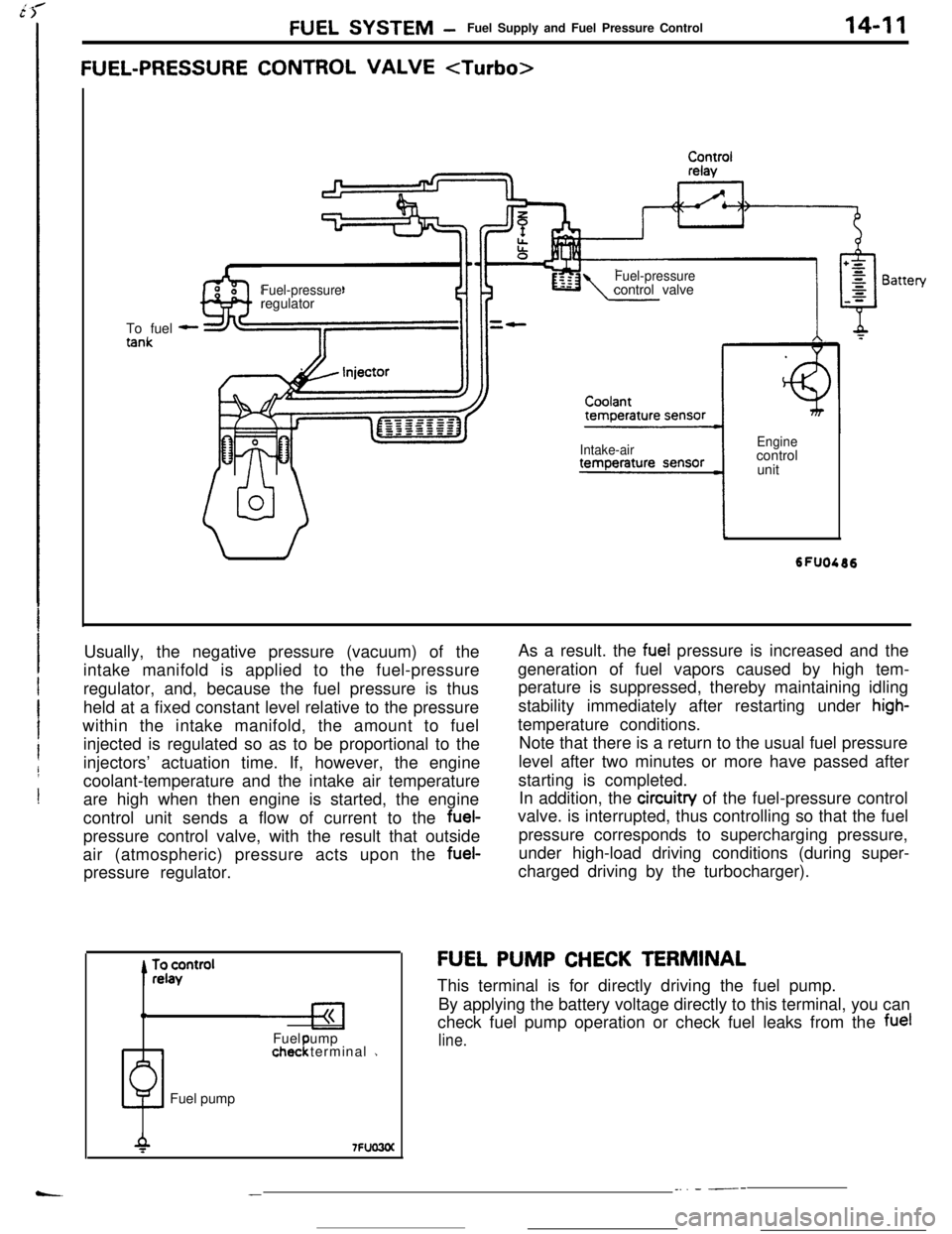
Usually, the negative pressure (vacuum) of the
intake manifold is applied to the fuel-pressure
regulator, and, because the fuel pressure is thus
held at a fixed constant level relative to the pressure
within the intake manifold, the amount to fuel
injected is regulated so as to be proportional to the
injectors’ actuation time. If, however, the engine
coolant-temperature and the intake air temperature
are high when then engine is started, the engine
control unit sends a flow of current to the fuel-
pressure control valve, with the result that outside
air (atmospheric) pressure acts upon the fuel-
pressure regulator.
0Fuel ump
1chec terminal 1!Fuel pumpAs a result. the
fuel pressure is increased and the
generation of fuel vapors caused by high tem-
perature is suppressed, thereby maintaining idling
stability immediately after restarting under
high-temperature conditions.
Note that there is a return to the usual fuel pressure
level after two minutes or more have passed after
starting is completed.
In addition, the circuitry of the fuel-pressure control
valve. is interrupted, thus controlling so that the fuel
pressure corresponds to supercharging pressure,
under high-load driving conditions (during super-
charged driving by the turbocharger).
FU,EL PUMP CHECK TERMINAL
This terminal is for directly driving the fuel pump.
By applying the battery voltage directly to this terminal, you can
check fuel pump operation or check fuel leaks from the
fuel
line.
__. - ---
Page 126 of 391
14-14
.._~- ---.FUEL SYSTEM
- Sensors
SENSORSRlUGENERAL DESCRIPTION
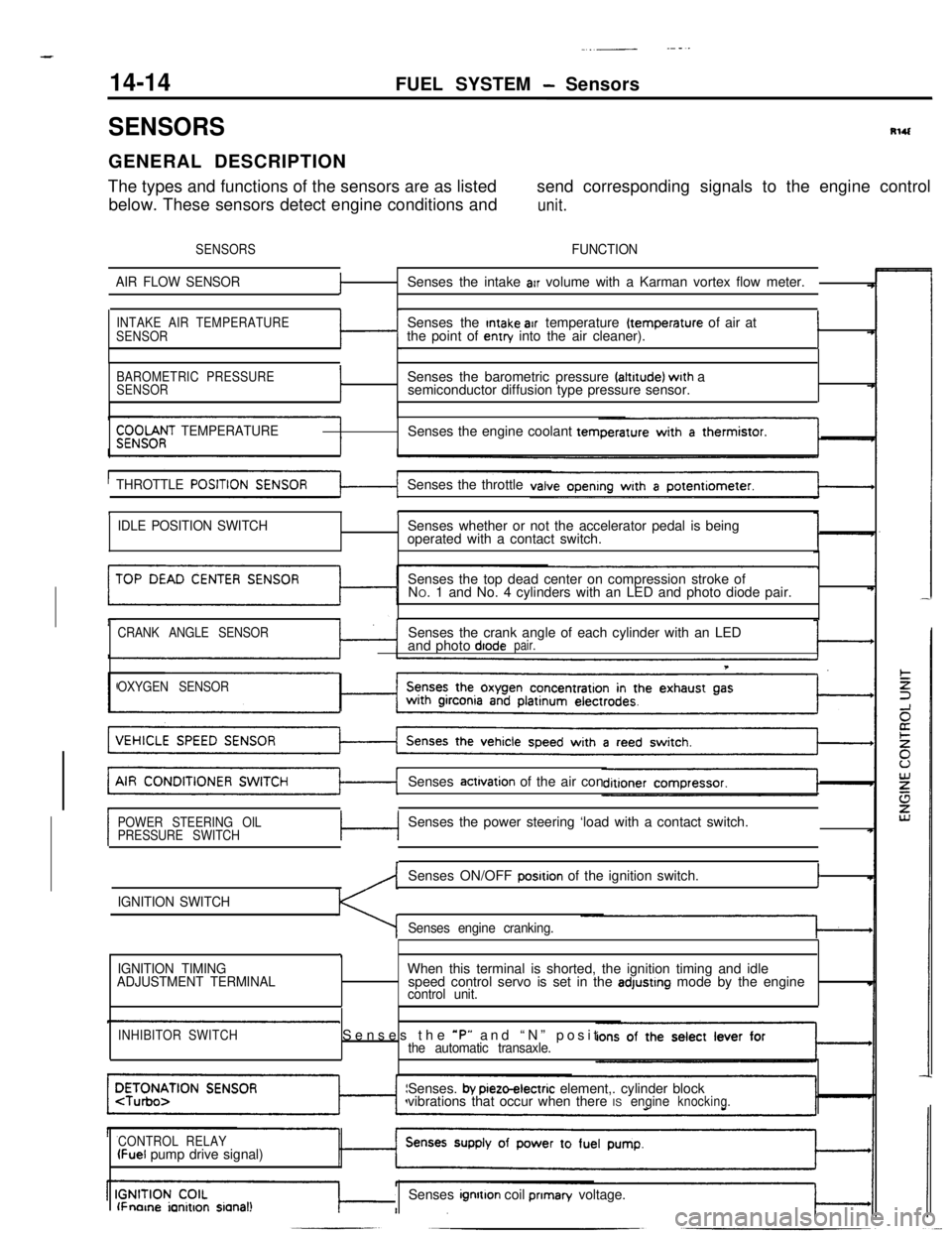
The types and functions of the sensors are as listedsend corresponding signals to the engine control
below. These sensors detect engine conditions and
unit.
SENSORSFUNCTION
AIR FLOW SENSOR
fSenses the intake arr volume with a Karman vortex flow meter.
INTAKE AIR TEMPERATURE
SENSORSenses the Intake air temperature (temperature of air at
the point of entry into the air cleaner).I
BAROMETRIC PRESSURE
SENSORISenses the barometric pressure faltrtude) wrth a
semiconductor diffusion type pressure sensor.
$;;OOf;T TEMPERATURESenses the engine coolant tern
THROTTLE
POSITISenses the throttle
tI
IDLE POSITION SWITCHSenses whether or not the accelerator pedal is being
operated with a contact switch.
Senses the top dead center on compression stroke of
NO. 1 and No. 4 cylinders with an LED and photo diode pair.
CRANK ANGLE SENSORSenses the crank angle of each cylinder with an LED
and photo diodepair.
T
OXYGEN SENSORSenses
actrvation of the air con
POWER STEERING OIL
PRESSURE SWITCHc-lSenses the power steering ‘load with a contact switch.
IGNITION SWITCHSenses ON/OFF
posrtion of the ignition switch.I
Senses engine cranking.
,
IGNITION TIMING
ADJUSTMENT TERMINALWhen this terminal is shorted, the ignition timing and idle
speed control servo is set in the adjustrng mode by the enginecontrol unit.
INHIBITOR SWITCHSenses the *P” and “N” positthe automatic transaxle.Senses.
by pieto-electric element,. cylinder block
vibrations that occur when there ISengineknocking.
CONTROL RELAY
(Fuel pump drive signal)
lFnorne ianitron sianal!Senses ignrtton coil prIman/ voltage.
Page 135 of 391
‘7JFUEL SYSTEM
- Sensors14-23AIR CONDITIONER SWITCH
Batten/
-31 .,Air conditioner unitlSAO735‘Air conditioner
control unitI”.._. ,voltage
Dual pressureswitch
-f@ -//Q.j
/
Coolanttemperature6FU1148
switch
Engine control unit
3Air conditioner
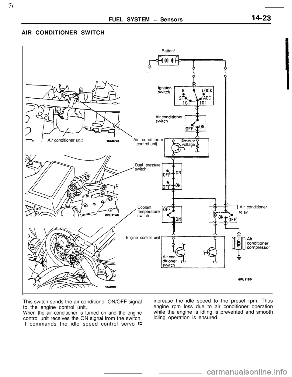
This switch sends the air conditioner ON/OFF signal
to the engine control unit.
When the air conditioner is turned on and the enginecontrol unit receives the ON
signal from the switch,
it commands the idle speed control servo
toincrease the idle speed to the preset rpm. Thus
engine rpm loss due to air conditioner operation
while the engine is idling is prevented and smooth
idling operation is ensured.
Page 139 of 391
‘73.- .-_ _ .-__ .- -..- - .-----___. _____^. -._ __--.
FUEL SYSTEM- Enaine Control Unit14-27
ENGINE CONTROL UNITRI4FhAA
GENERAL DESCRIPTIONEngine control unit
~
~~:~~~~~~~~~:~~
~. . . . .. .. . . . ... . . . . ... .. :+:.:.:.:.:.:.:.~.:.~+~.
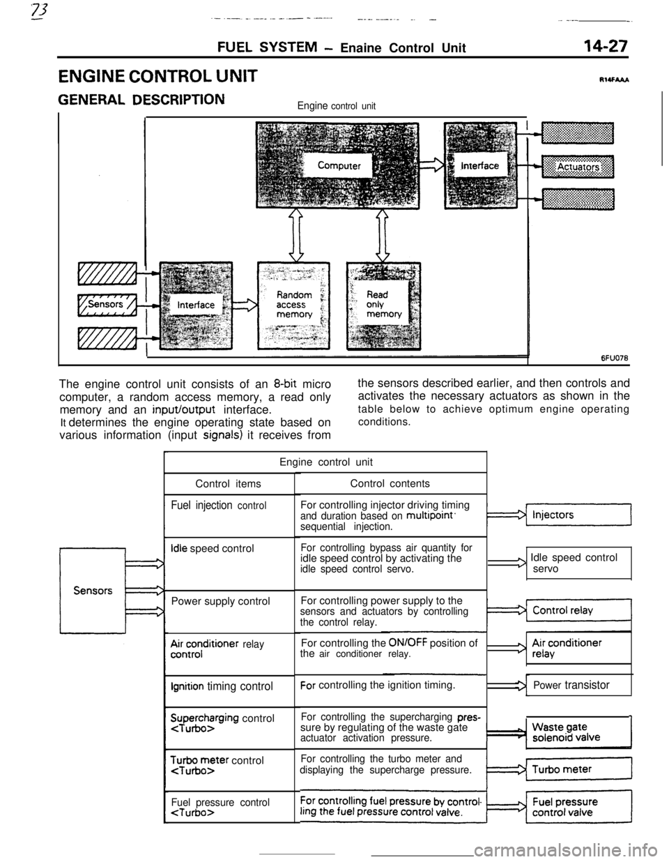
6FUO76The engine control unit consists of an
8-bit micro
computer, a random access memory, a read only
memory and an input/output interface.
It determines the engine operating state based on
various information (input
signals) it receives fromthe sensors described earlier, and then controls and
activates the necessary actuators as shown in the
table below to achieve optimum engine operating
conditions.
Engine control unit
Control items
Fuel injection control
Idle speed control
Power supply control
A&;;;ditioner relay
Ignition timing control
SuTpuegohzrging control
$r;ir;;ter control
Fuel pressure control
For controlling injector driving timing
and duration based on multipoint’sequential injection.
For controlling bypass air quantity foridle speed control by activating the
idle speed control servo.
I3 Idle speed control
servo
For controlling power supply to the
sensors and actuators by controlling
the control relay.For controlling the
ON/OFF position of
the air conditioner relay.For controlling the ignition timing.
For controlling the supercharging pres-sure by regulating of the waste gate
actuator activation pressure.
For controlling the turbo meter and
displaying the supercharge pressure.
3 Ai;acenditioner
Power transistor
1
Page 141 of 391
FUEL SYSTEM- Engine Control Unit14-29
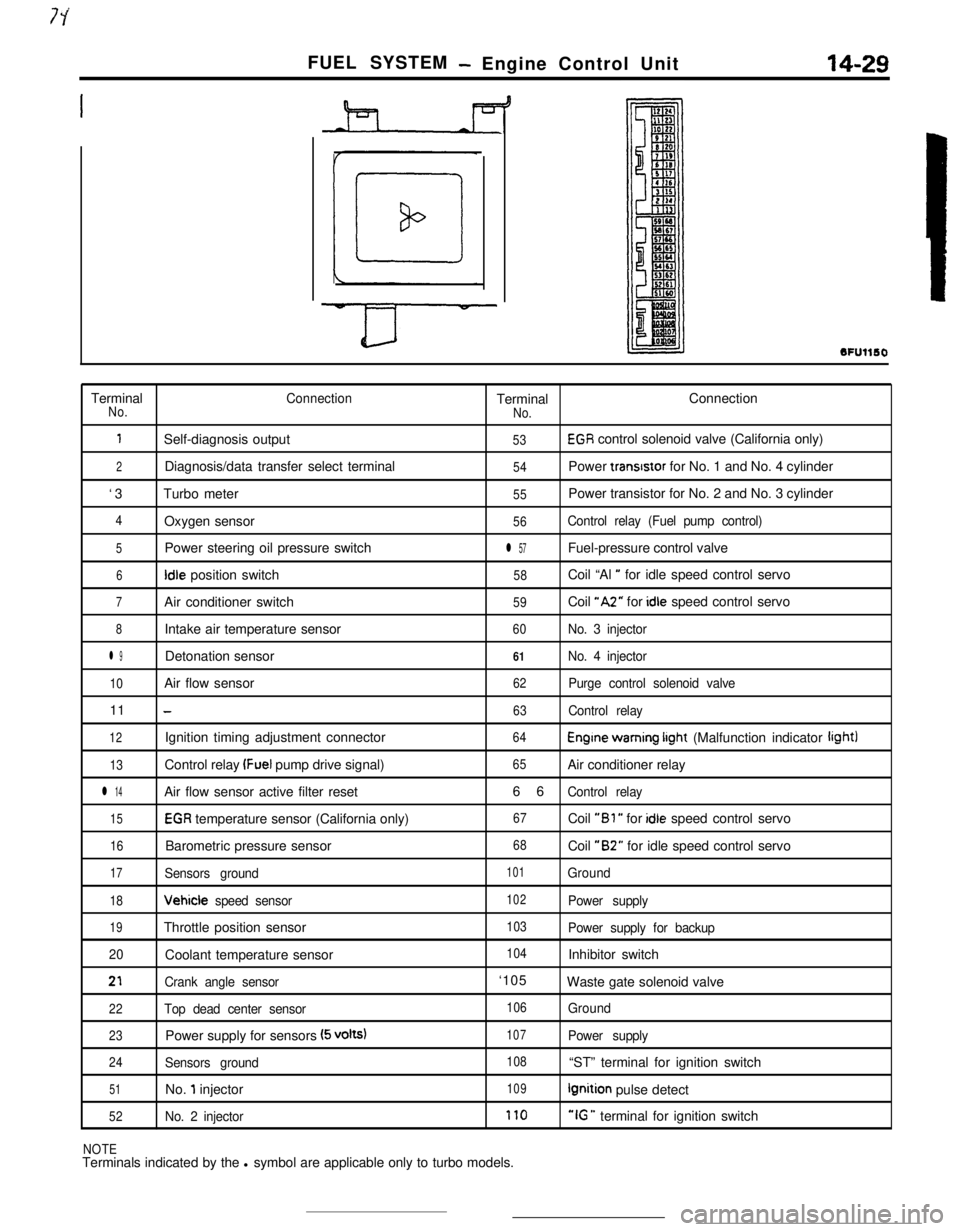
SFUllSOTerminal
ConnectionTerminalConnectionNo.
No.
1Self-diagnosis output53EGR control solenoid valve (California only)
2Diagnosis/data transfer select terminal54Power transrstor for No. 1 and No. 4 cylinder
‘3Turbo meter
55Power transistor for No. 2 and No. 3 cylinder
4Oxygen sensor56Control relay (Fuel pump control)
5Power steering oil pressure switchl 57Fuel-pressure control valve
6Idle position switch58Coil “Al ” for idle speed control servo
7Air conditioner switch59Coil “A2” for idle speed control servo
8Intake air temperature sensor60No. 3 injector
l 9Detonation sensor61No. 4 injector
10Air flow sensor62Purge control solenoid valve11
-63Control relay
12Ignition timing adjustment connector64Engine warning irght (Malfunction indicator light)
13Control relay (Fuel pump drive signal)65Air conditioner relay
l 14Air flow sensor active filter reset66Control relay
15EGR temperature sensor (California only)67Coil “Bl ” for idle speed control servo
16Barometric pressure sensor68Coil “B2” for idle speed control servo
17Sensors ground101Ground
18Vehicle speed sensor102Power supply
19Throttle position sensor103Power supply for backup
20Coolant temperature sensor
104Inhibitor switch
21Crank angle sensor‘105
Waste gate solenoid valve
22Top dead center sensor106Ground
23Power supply for sensors (5 volts)107Power supply
24Sensors ground108“ST” terminal for ignition switch
51No. 1 injector109Ignition pulse detect
52No. 2 injector170“IG ” terminal for ignition switch
NOTETerminals indicated by the l symbol are applicable only to turbo models.
Page 145 of 391
FUEL SYSTEM- Fuel Injection Control14-33
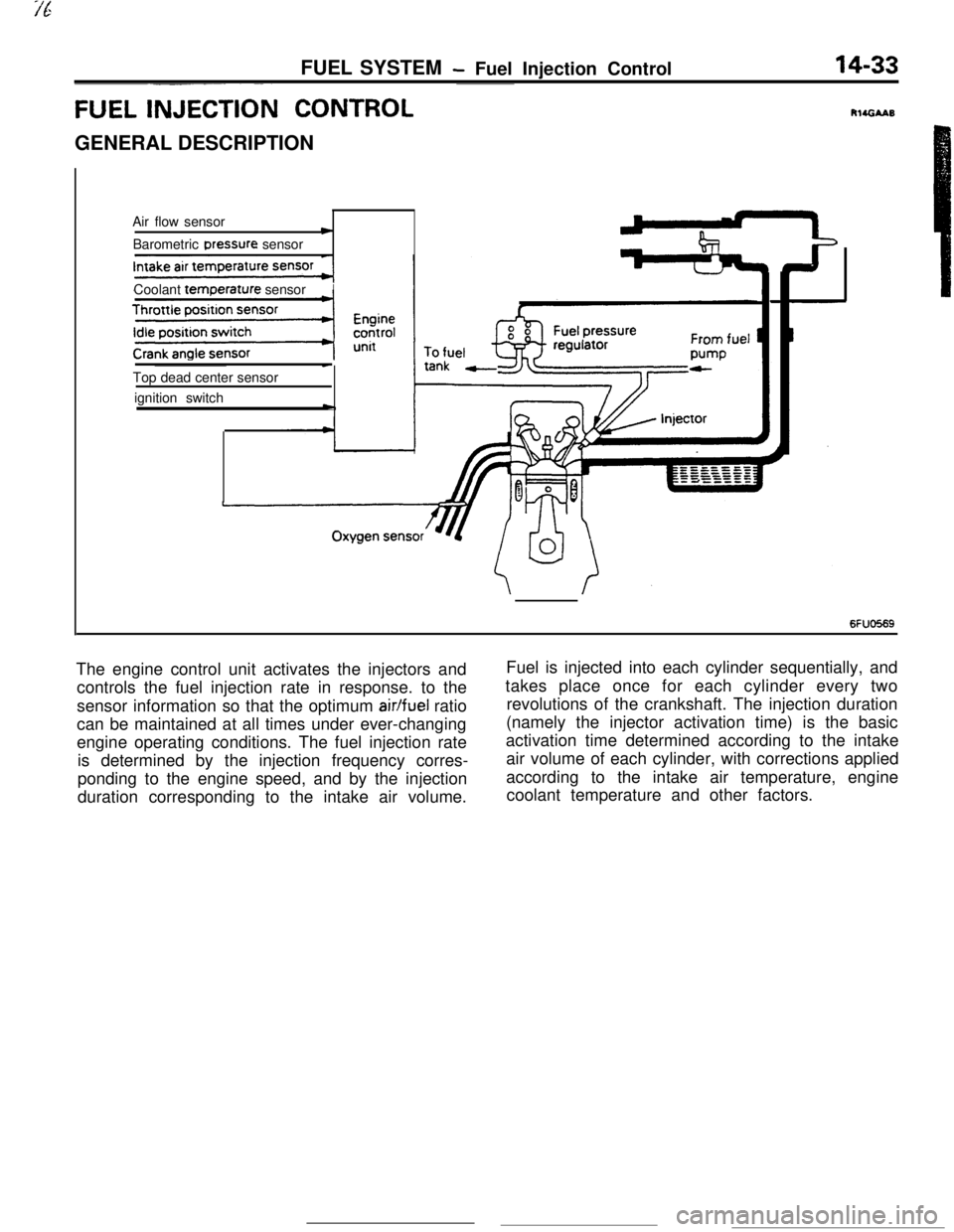
FUEL INJECTI& CONTROLGENERAL DESCRIPTION
Air flow sensor
cBarometric Dressure sensor
Coolant
temr3erature sensorITop dead center sensor
ignition switch
-
c
6FUO569The engine control unit activates the injectors andFuel is injected into each cylinder sequentially, and
controls the fuel injection rate in response. to thetakes place once for each cylinder every two
sensor information so that the optimum
air/fuel ratiorevolutions of the crankshaft. The injection duration
can be maintained at all times under ever-changing(namely the injector activation time) is the basic
engine operating conditions. The fuel injection rateactivation time determined according to the intake
is determined by the injection frequency corres-air volume of each cylinder, with corrections applied
ponding to the engine speed, and by the injectionaccording to the intake air temperature, engine
duration corresponding to the intake air volume.coolant temperature and other factors.
Page 151 of 391
FUEL SYSTEM- Fuel Injection Control14-39FUEL INJECTION AMOUNT CONTROL (INJECTOR ACTIVATION DURATION CON-
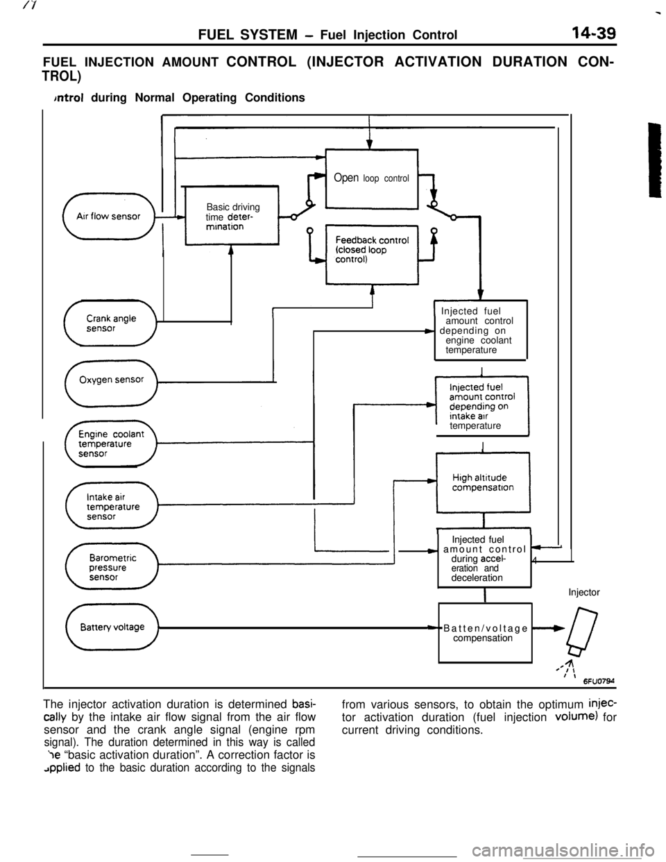
TROL)
bntrol during Normal Operating Conditions
Open loop control
( ArrflowsensorBasic driving
time deter-
-”mination
i( Injected fuel
amount control
s depending on
engine coolant
temperature
I
II
””compensatron
Injected fuel Injected fuel
c amount control t-c amount control t-during accel-during accel-4 4eration and eration anddeceleration decelerationIIInjector Injector
+ Batten/voltage --W+ Batten/voltage --Wcompensation compensation
QQ44=I,=I,f \f \6FU07M6FU07Mtemperature
II
The injector activation duration is determined
basi-
tally by the intake air flow signal from the air flow
sensor and the crank angle signal (engine rpm
signal). The duration determined in this way is called‘le “basic activation duration”. A correction factor is
applied to the basic duration according to the signalsfrom various sensors, to obtain the optimum
injec-tor activation duration (fuel injection volume) for
current driving conditions.
Page 152 of 391
14-40FUEL SYSTEM - Fuel Injection Control
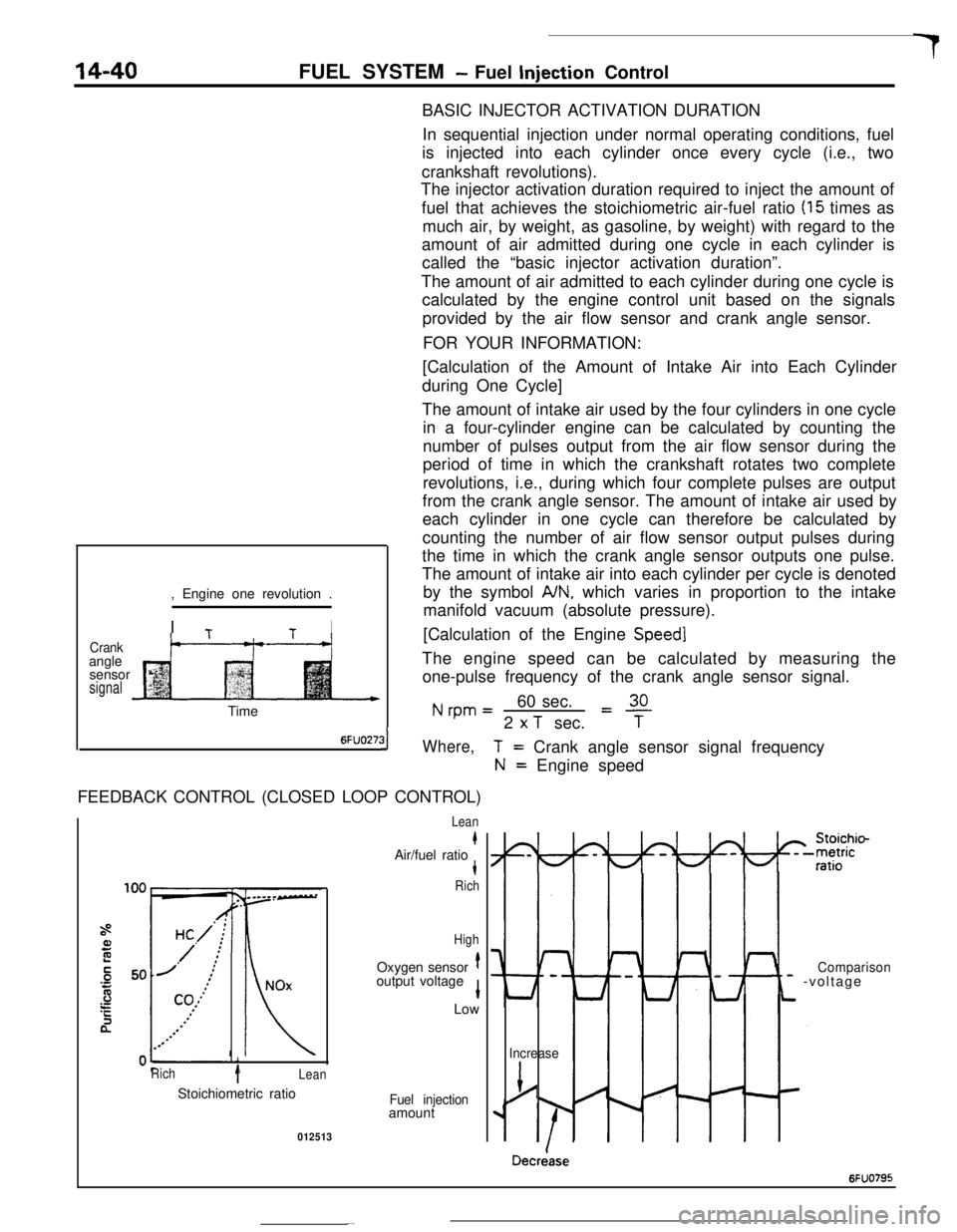
BASIC INJECTOR ACTIVATION DURATION
In sequential injection under normal operating conditions, fuel
is injected into each cylinder once every cycle (i.e., two
crankshaft revolutions).
The injector activation duration required to inject the amount of
fuel that achieves the stoichiometric air-fuel ratio
(15 times as
much air, by weight, as gasoline, by weight) with regard to the
amount of air admitted during one cycle in each cylinder is
called the “basic injector activation duration”.
The amount of air admitted to each cylinder during one cycle is
calculated by the engine control unit based on the signals
provided by the air flow sensor and crank angle sensor.
FOR YOUR INFORMATION:
Crankangle
sensor
signal, Engine one revolution .
I
TtI
t--“---t-+[Calculation of the Amount of Intake Air into Each Cylinder
during One Cycle]
The amount of intake air used by the four cylinders in one cycle
in a four-cylinder engine can be calculated by counting the
number of pulses output from the air flow sensor during the
period of time in which the crankshaft rotates two complete
revolutions, i.e., during which four complete pulses are output
from the crank angle sensor. The amount of intake air used by
each cylinder in one cycle can therefore be calculated by
counting the number of air flow sensor output pulses during
the time in which the crank angle sensor outputs one pulse.
The amount of intake air into each cylinder per cycle is denoted
by the symbol
A/N, which varies in proportion to the intake
manifold vacuum (absolute pressure).
[Calculation of the Engine
Speed]The engine speed can be calculated by measuring the
one-pulse frequency of the crank angle sensor signal.
Nrpm=60 sec.L!!L2
x T sec.TTime
6FUO27:31Where,FEEDBACK CONTROL (CLOSED LOOP CONTROL)
i
Rich1Lean
T= Crank angle sensor signal frequency
N= Engine speed
Lean
kAir/fuel ratiot
Rich
HighOxygen sensor
toutput voltage
1Low
Stoichiometric ratio
Fuel injectionamount
012513
I-
Lt
Comparison- -voltage
Increase
j/
Decriase
6FUO795
Page 153 of 391
FUEL SYSTEM -Fuel Injection Control
14-41
During normal operation (including idling), the en-
gine control unit controls the injector activation time
tcThieve the stoichiometric air/fuel ratio, which
e.;res maximum efficiency of the catalytic conver-
ter, on the basis of the oxygen sensor signal.
When the air/fuel mixture is richer than the
stoichiometric ratio, there is less oxygen in the
exhaust gas and thus the oxygen sensor output
voltage is higher; hence a “mixture rich” signal is
input to the engine control unit. Then, the engine
control unit decreases the amount of fuel injected. If
the air/fuel ratio decreases to the point that and the
mixture becomes leaner than the stoichiometric
ratio, the oxygen concentration in the exhaust gas
increases and the oxygen sensor output voltage
becomes lower. Then, a “mixture lean” signal isinput to the engine control unit.
Upon input of this signal, the engine control unit
increases the feedback correction factor, thus caus-
ing more fuel to be injected.
By means of the above-mentioned controls (collec-
tively called “feedback control”), the air-fuel mixture
is maintained at the stoichiometric ratio.
Under the following specific conditions, this feed-
back control is not performed, in order to improve
driveability.
(11
(2)
::I
(5)While cranking the engine
During engine warm-up when engine coolant
temperature is less than
45°C (113°F)During acceleration/deceleration
During high load operation
When oxygen sensor is not functioning
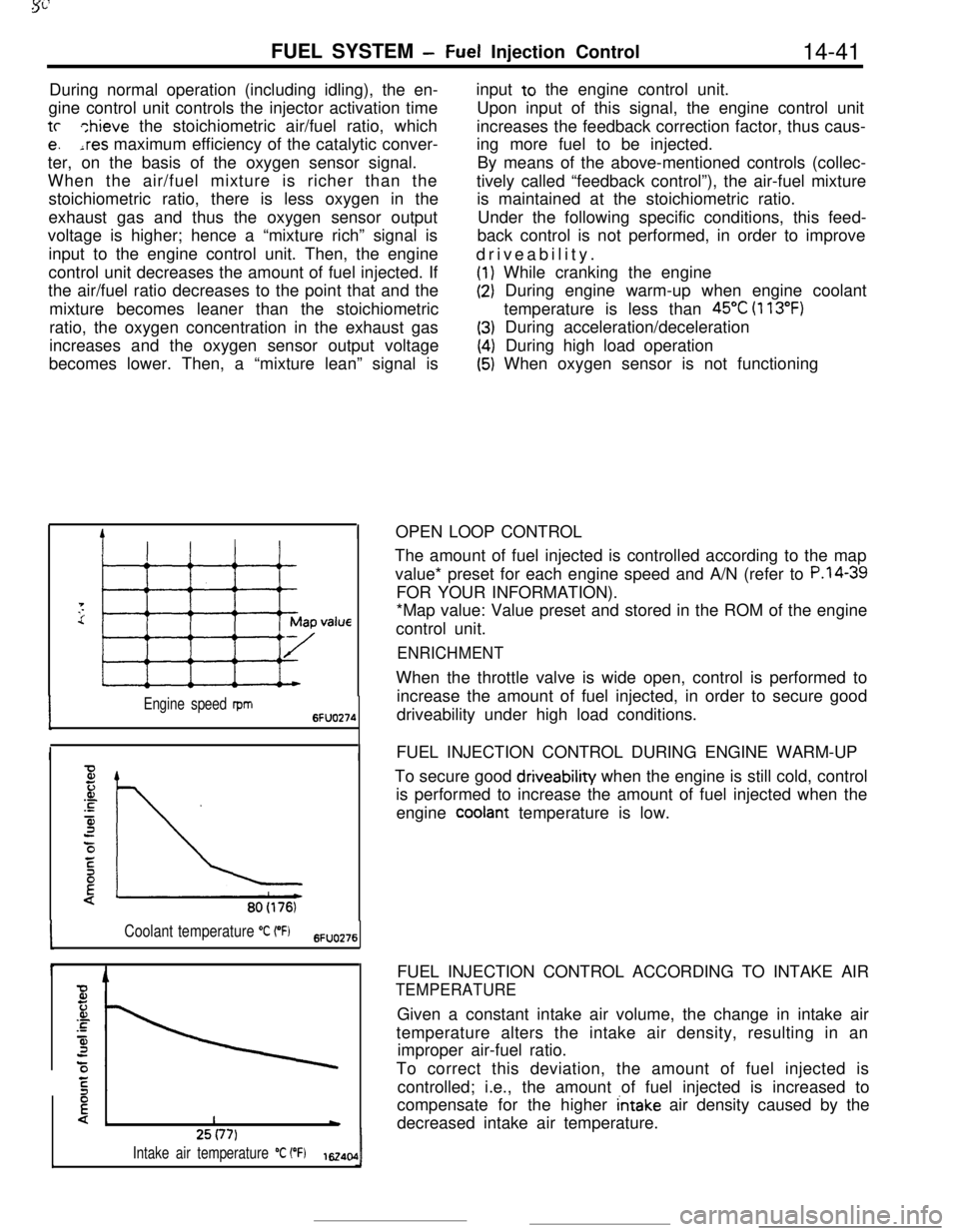
IOPEN LOOP CONTROL
Engine speed rpm6FUO274
II
80(176)
Coolant temperature “C (“Fj6FlJO276
I425(77)
Intake air temperature “C (“F)1~40,0IThe amount of fuel injected is controlled according to the map
value* preset for each engine speed and A/N (refer to
P.l4-39FOR YOUR INFORMATION).
*Map value: Value preset and stored in the ROM of the engine
control unit.
ENRICHMENTWhen the throttle valve is wide open, control is performed to
increase the amount of fuel injected, in order to secure good
driveability under high load conditions.
FUEL INJECTION CONTROL DURING ENGINE WARM-UP
To secure good driveability when the engine is still cold, control
is performed to increase the amount of fuel injected when the
engine
cooiant temperature is low.
FUEL INJECTION CONTROL ACCORDING TO INTAKE AIR
TEMPERATUREGiven a constant intake air volume, the change in intake air
temperature alters the intake air density, resulting in an
improper air-fuel ratio.
To correct this deviation, the amount of fuel injected is
controlled; i.e., the amount of fuel injected is increased to
compensate for the higher
intake air density caused by the
decreased intake air temperature.