engine oil MITSUBISHI ECLIPSE 1990 Owner's Guide
[x] Cancel search | Manufacturer: MITSUBISHI, Model Year: 1990, Model line: ECLIPSE, Model: MITSUBISHI ECLIPSE 1990Pages: 391, PDF Size: 15.27 MB
Page 146 of 391
-
14-34FUEL SYSTEM - Fuel Injection Control
TDC sensorAir flow sensor
I
Reading of input signal1
I ,,
uOperation mode decisionOperation mode decision data
I rBasic valve opening time data
Enginecontrol unitInjector activation time control
Injector activation pulse generationControl factor data of
engine coolant temperature,
intake air temperature and
barometric pressure, etc.
Injector1
6FUO766Needle valveFilter
Connector
Solenoid coil
Plunger
-4
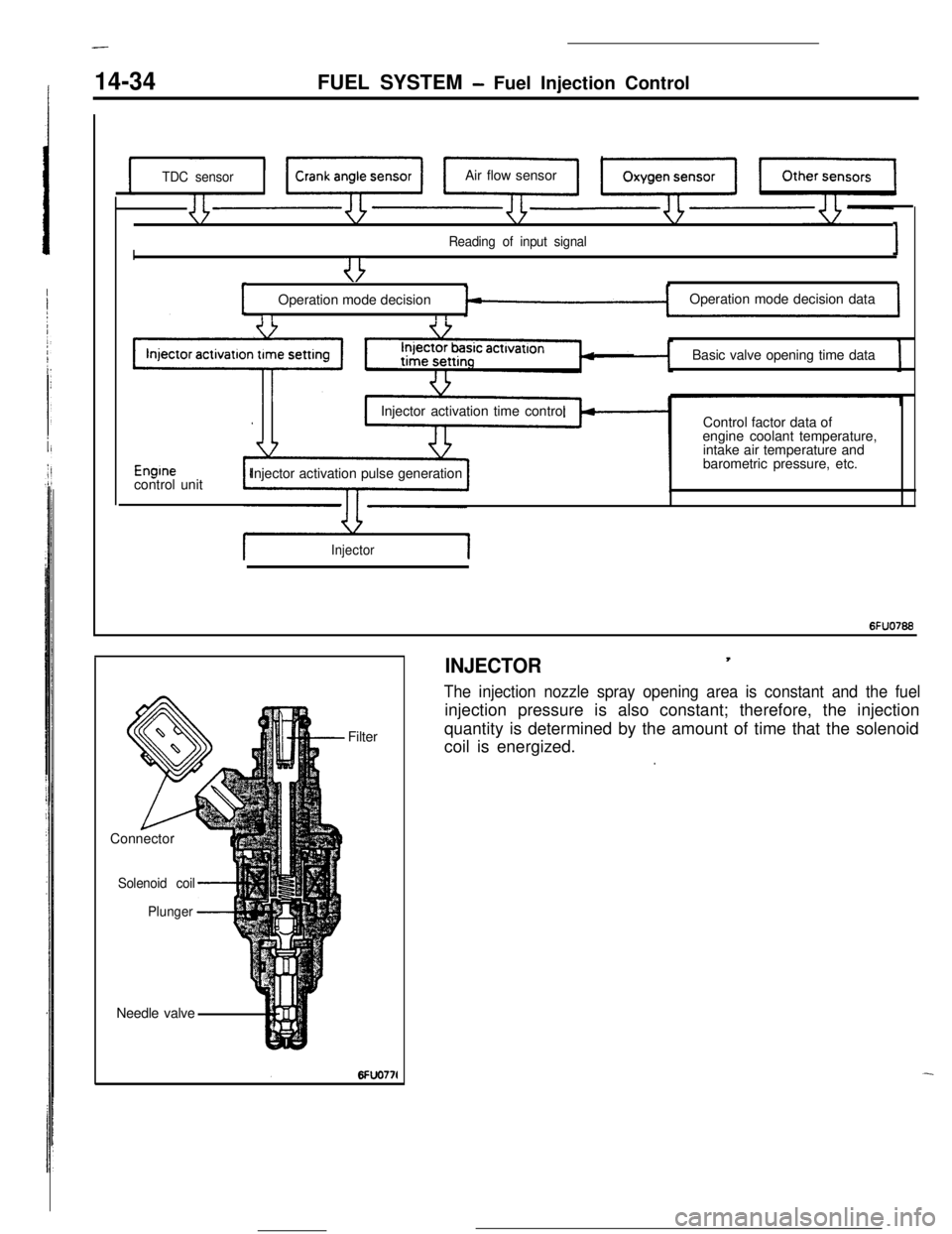
INJECTOR,
The injection nozzle spray opening area is constant and the fuelinjection pressure is also constant; therefore, the injection
quantity is determined by the amount of time that the solenoid
coil is energized.
.
Page 154 of 391
14-42
FUEL SYSTEM- Fuel Injection Control
4
Fz.or.c
4:0/
E
{!*760 (301Barometric pressure
mmHg (in.Hg) 6Fuo9z
c
Timet
6FUO279Drivecurrent
0: bri
F2JJ’ ipe; II
I+-JValve opening timi16240:
E‘C
F
.-
is
3
3:\Battery voltage
V162406
80 (176)Coolant temperature
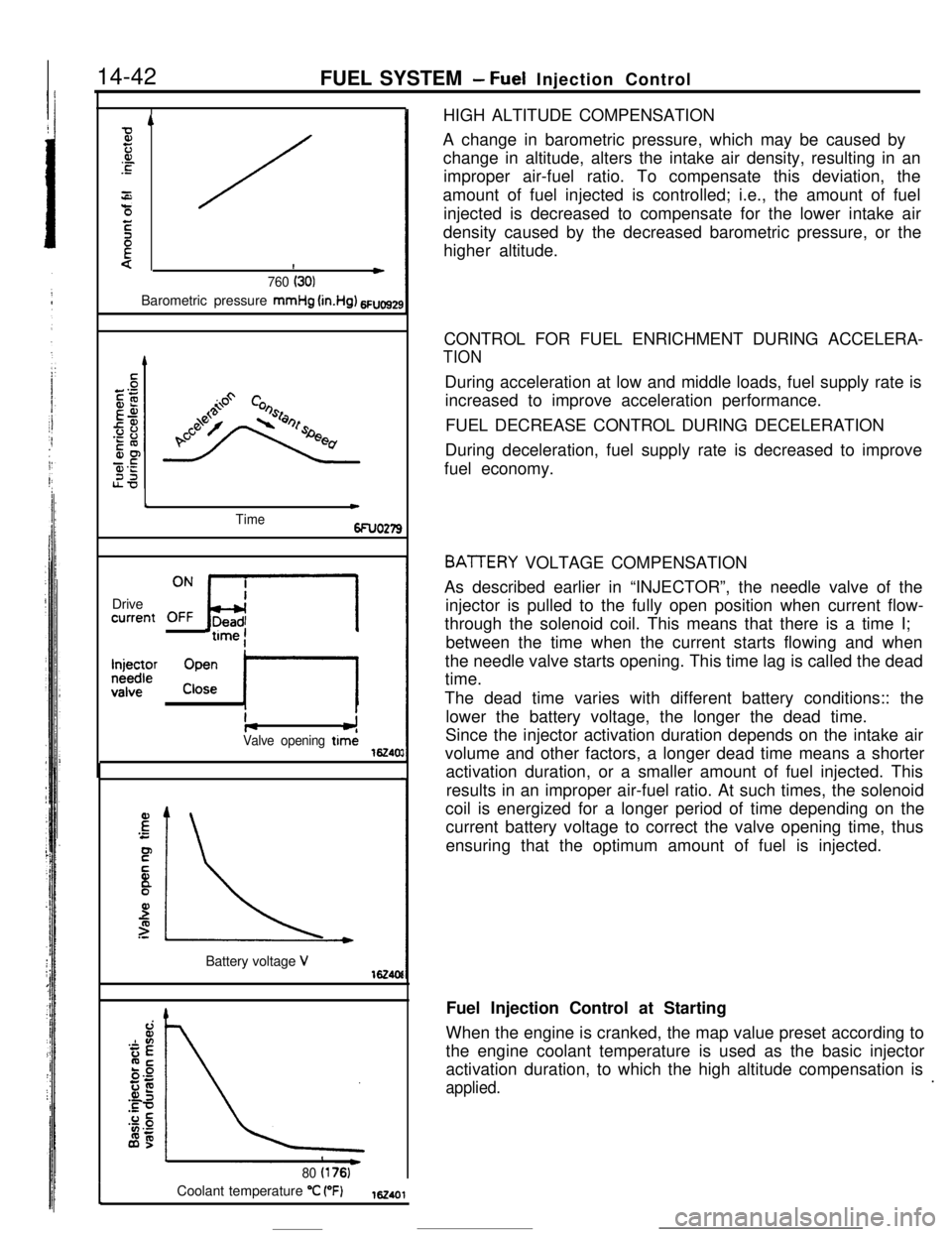
“C (“F)162401HIGH ALTITUDE COMPENSATION
A change in barometric pressure, which may be caused by
change in altitude, alters the intake air density, resulting in an
improper air-fuel ratio. To compensate this deviation, the
amount of fuel injected is controlled; i.e., the amount of fuel
injected is decreased to compensate for the lower intake air
density caused by the decreased barometric pressure, or the
higher altitude.
CONTROL FOR FUEL ENRICHMENT DURING ACCELERA-
TIONDuring acceleration at low and middle loads, fuel supply rate is
increased to improve acceleration performance.
FUEL DECREASE CONTROL DURING DECELERATION
During deceleration, fuel supply rate is decreased to improve
fuel economy.
BATTERY VOLTAGE COMPENSATION
As described earlier in “INJECTOR”, the needle valve of the
injector is pulled to the fully open position when current flow-
through the solenoid coil. This means that there is a time I;
between the time when the current starts flowing and when
the needle valve starts opening. This time lag is called the dead
time.
The dead time varies with different battery conditions:: the
lower the battery voltage, the longer the dead time.
Since the injector activation duration depends on the intake air
volume and other factors, a longer dead time means a shorter
activation duration, or a smaller amount of fuel injected. This
results in an improper air-fuel ratio. At such times, the solenoid
coil is energized for a longer period of time depending on the
current battery voltage to correct the valve opening time, thus
ensuring that the optimum amount of fuel is injected.
Fuel Injection Control at Starting
When the engine is cranked, the map value preset according to
the engine coolant temperature is used as the basic injector
activation duration, to which the high altitude compensation is
applied..
Page 158 of 391
.
14-46FUEL SYSTEM- Idle Speed Control
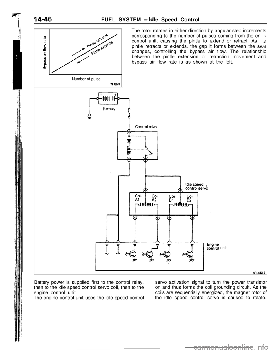
The rotor rotates in either direction by angular step increments
corresponding to the number of pulses coming from the en
?control unit, causing the pintle to extend or retract. As
pintle retracts or extends, the gap it forms between the
sea:changes, controlling the bypass air flow. The relationship
between the pintle extension or retraction movement and
bypass air flow rate is as shown at the left.
Number of pulse
7F UW(Control relay
@iI---
unit
Battery power is supplied first to the control relay,
then to the idle speed control servo coil, then to theservo activation signal to turn the power transistor
engine control unit.on and thus forms the coil grounding circuit. As the
The engine control unit uses the idle speed controlcoils are sequentially energized, the magnet rotor of
the idle speed control servo is caused to rotate.
Page 159 of 391
FUEL SYSTEM- Idle Speed Control14-47Operating Principles of Stepper Motor
Stator ICoil Al and
A2 e
Stator II
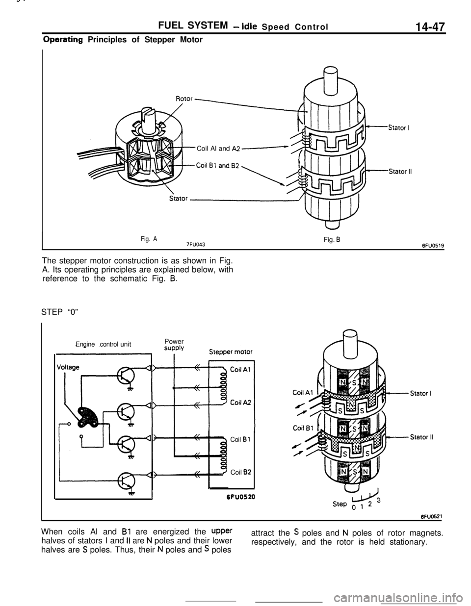
Fig. A7FUO43Fig. B6FUO519The stepper motor construction is as shown in Fig.
A. Its operating principles are explained below, with
reference to the schematic Fig.
8.STEP “0”
Engine controlunitPower
Coil B 1Coil
B2
I6FU0520
- Stator IStator
II
U
LdStep o 1 23When coils Al and
Bl are energized the upperhalves of stators I and
II are N poles and their lower
halves are
S poles. Thus, their N poles and S polesattract the
S poles and N poles of rotor magnets.
respectively, and the rotor is held stationary.
Page 160 of 391
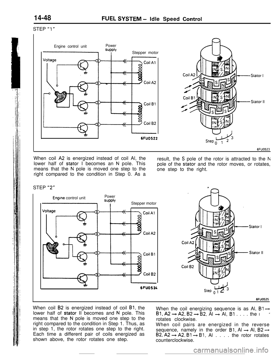
14-48STEP
“1”
FUEL SYSTEM - Idle Speed Control
Engine control unitPowerSUPPlYI IStepper motor
Stator I
Stator II
I6FUO522When coil
A2 is energized instead of coil Al, the
lower half of stator I becomes an
N pole. This
means that the
N pole is moved one step to the
right compared to the condition in Step 0. As aresult, the
S pole of the rotor is attracted to the Npole of the stator and the rotor moves, or rotates,
one step to the right.
STEP
“2”
Engine control unitPower
=JPPb
1 IStepper motor
Stator IStator II
mI6FU0524w3Step o 1 2
6FUO525When coil
B2 is energized instead of coil Bl, the
lower half of stator II becomes and
N pole. This
means that the
N pole is moved one step to the
right compared to the condition in Step 1. Thus, as
in step 1, the rotor rotates one step to the right.
Each time a different pair of coils energized as
shown above, the rotor rotates one step.When the coil energizing sequence is as Al, B!
3
Bl, A2 -) A2. B2 + B2. Al + Al, Bl . . . . the I*rotates clockwise.
When coil pairs are energized in the reverse
sequence, namely in the order
Bl, Al + Al, B2 -)
B2, A2 --) A2, Bl 3 Bl, Al . . . . the rotor rotates
counterclockwise.
Page 161 of 391
FUEL SYSTEM -Idle Speed Control14-49
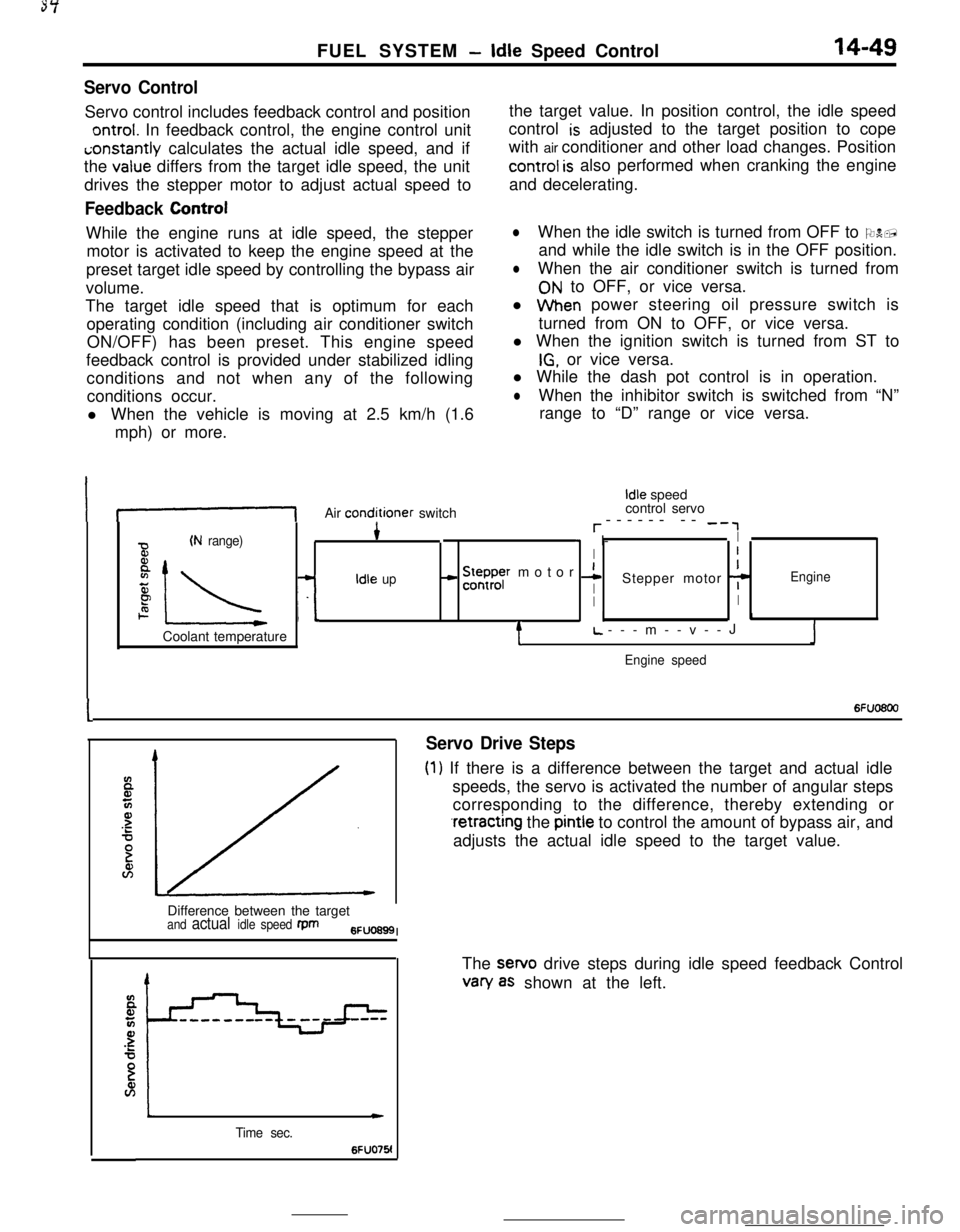
Servo ControlServo control includes feedback control and position
ontrol. In feedback control, the engine control uniti;onstantly calculates the actual idle speed, and if
the
value differs from the target idle speed, the unit
drives the stepper motor to adjust actual speed to
Feedback ControlWhile the engine runs at idle speed, the stepper
motor is activated to keep the engine speed at the
preset target idle speed by controlling the bypass air
volume.
The target idle speed that is optimum for each
operating condition (including air conditioner switch
ON/OFF) has been preset. This engine speed
feedback control is provided under stabilized idling
conditions and not when any of the following
conditions occur.
l When the vehicle is moving at 2.5 km/h (1.6
mph) or more.the target value. In position control, the idle speed
control
is adjusted to the target position to cope
with air conditioner and other load changes. Position
control is also performed when cranking the engine
and decelerating.
lWhen the idle switch is turned from OFF to ON,
and while the idle switch is in the OFF position.
lWhen the air conditioner switch is turned from
ON to OFF, or vice versa.
l When power steering oil pressure switch is
turned from ON to OFF, or vice versa.
l When the ignition switch is turned from ST to
IG, or vice versa.
l While the dash pot control is in operation.
lWhen the inhibitor switch is switched from “N”
range to “D” range or vice versa.
If-1Air conditioner switch
Idle speed
control servo
r------ -- -‘,
(N range)4* I-I
BI
8
IL -L
- !5ysr motor 1I
zIdle upIStepper motor 7Engine
PII2. I.1Coolant temperature
tL.---m--v--JJ
Engine speed
I6Fuo6oo
Servo Drive Steps
(1) If there is a difference between the target and actual idle
speeds, the servo is activated the number of angular steps
corresponding to the difference, thereby extending or
.retracting the pintle to control the amount of bypass air, and
adjusts the actual idle speed to the target value.
Difference between the target
and actual idle speed fpm6FUO699I
Time sec.
c
6FUO76!The sewo drive steps during idle speed feedback Control
van/ as shown at the left.
Page 162 of 391
14-50FUEL SYSTEM- Idle Speed Control
SDeed adiustina screwI -Throttle valve
Lw-3O(-22) 0132) 30(86! 601140) 9ofl94)Coolant temperature
“C (OF)6FUO641
E94
72--2--I
Q--.-.-z
3201.000 --4-\-\
5P9.o%IIIaI L-2O(-41 Of3214Of104)801176)Coolant temperature
“C VF)6FU028E
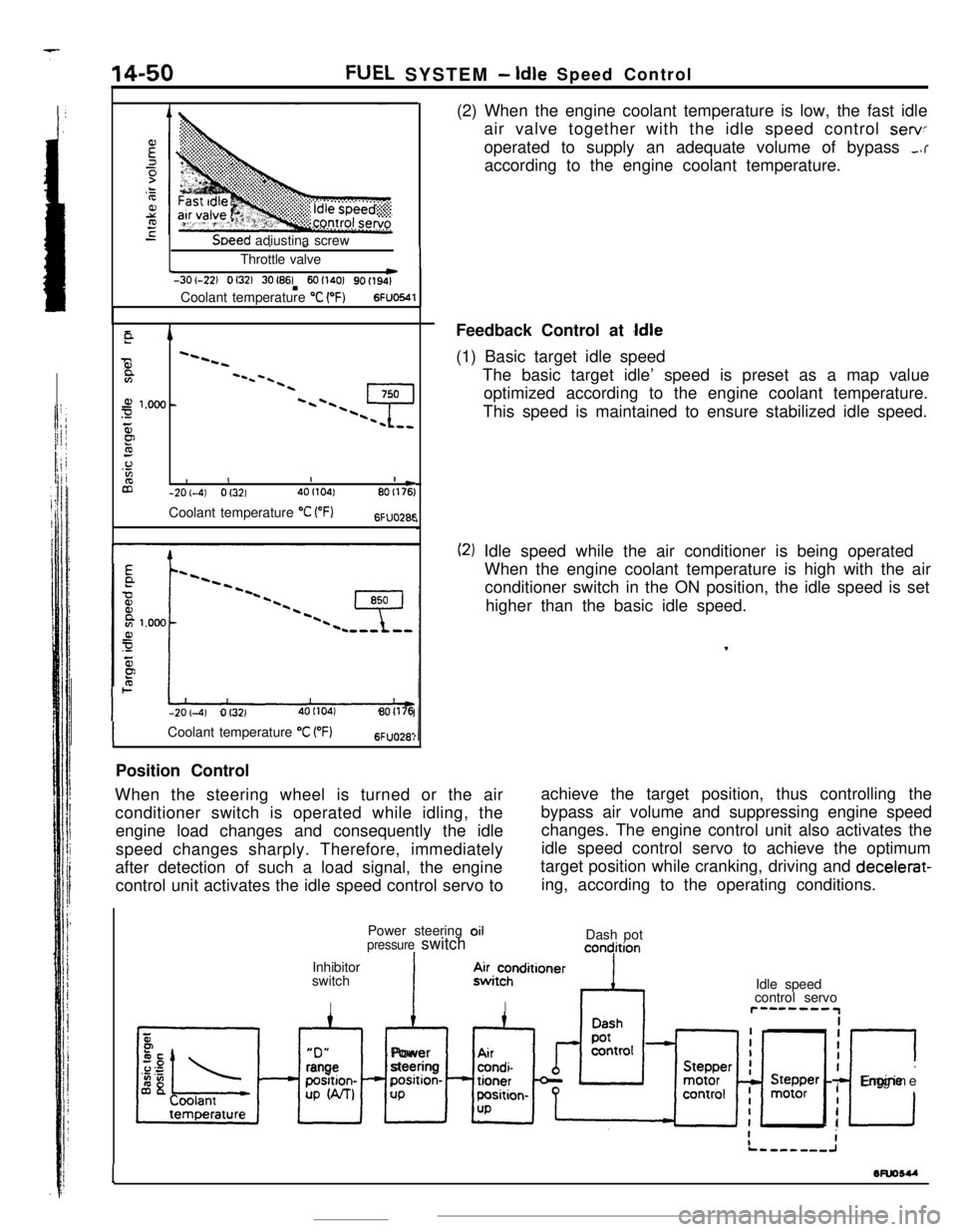
-201-4) Of3214OI104180(176(2) When the engine coolant temperature is low, the fast idle
air valve together with the idle speed control
servoperated to supply an adequate volume of bypass
,.raccording to the engine coolant temperature.
Feedback Control at
Idle(1) Basic target idle speed
The basic target idle’ speed is preset as a map value
optimized according to the engine coolant temperature.
This speed is maintained to ensure stabilized idle speed.
(2) Idle speed while the air conditioner is being operated
When the engine coolant temperature is high with the air
conditioner switch in the ON position, the idle speed is set
higher than the basic idle speed.
,
ICoolant temperature “C VF)6FUO28:Position Control
When the steering wheel is turned or the air
conditioner switch is operated while idling, theachieve the target position, thus controlling the
engine load changes and consequently the idlebypass air volume and suppressing engine speed
changes. The engine control unit also activates the
speed changes sharply. Therefore, immediately
after detection of such a load signal, the engine
control unit activates the idle speed control servo toidle speed control servo to achieve the optimum
target position while cranking, driving and decelerat-
ing, according to the operating conditions.
Power steering oil
pressure switchIInhibitor
switch
IDash pot
concjition“D”
xl
rangeposition-
UP W-U
IAlPower
steeringposition-
UP.4~i~hnditioner
IIdle speed
control servor”--““IiiI
I
c
IEngine
I
I
1wuosu
-
Page 163 of 391
FUEL SYSTEM -Idle Speed Control14-51
_ 0 (32)80 (175)Coolant temperature “C (“F)6FUO2653
ATarget position during operation
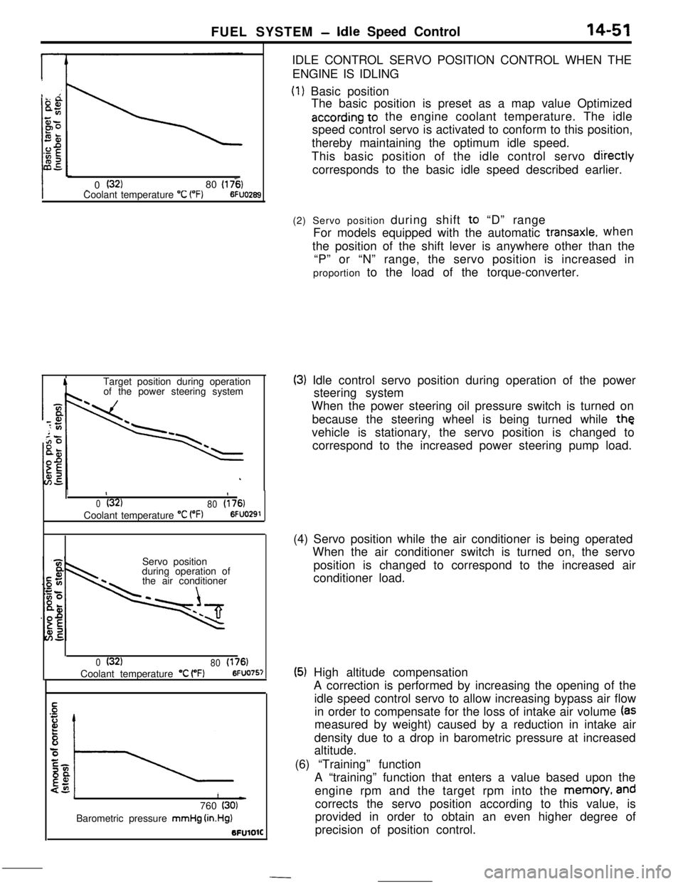
of the power steering systemIDLE CONTROL SERVO POSITION CONTROL WHEN THE
ENGINE IS IDLING
(1) Basic position
The basic position is preset as a map value Optimized
according to the engine coolant temperature. The idle
speed control servo is activated to conform to this position,
thereby maintaining the optimum idle speed.
This basic position of the idle control servo
diiectlycorresponds to the basic idle speed described earlier.
1II
0(32)
80(176)Coolant temperature
“C VW6FUO291Servo position
during operation of
the air conditioner
0(32)
80(176)Coolant temperature “C (“F)6FUO757
1L)760 (30)Barometric pressure mmHg
(in.Hg)BFUlOlC(2) Servo position during shift to “D” range
For models equipped with the automatic
transaxle.when
the position of the shift lever is anywhere other than the
“P” or “N” range, the servo position is increased in
proportion to the load of the torque-converter.
(3) Idle control servo position during operation of the power
steering system
When the power steering oil pressure switch is turned on
because the steering wheel is being turned while
thevehicle is stationary, the servo position is changed to
correspond to the increased power steering pump load.
(4) Servo position while the air conditioner is being operated
When the air conditioner switch is turned on, the servo
position is changed to correspond to the increased air
conditioner load.
(5) High altitude compensation
A correction is performed by increasing the opening of the
idle speed control servo to allow increasing bypass air flow
in order to compensate for the loss of intake air volume
(asmeasured by weight) caused by a reduction in intake air
density due to a drop in barometric pressure at increased
altitude.
(6) “Training” function
A “training” function that enters a value based upon the
engine rpm and the target rpm into the memon/,
andcorrects the servo position according to this value, is
provided in order to obtain an even higher degree of
precision of position control.
Page 166 of 391
FUEL SYSTEM- Power Supply Control
Battery
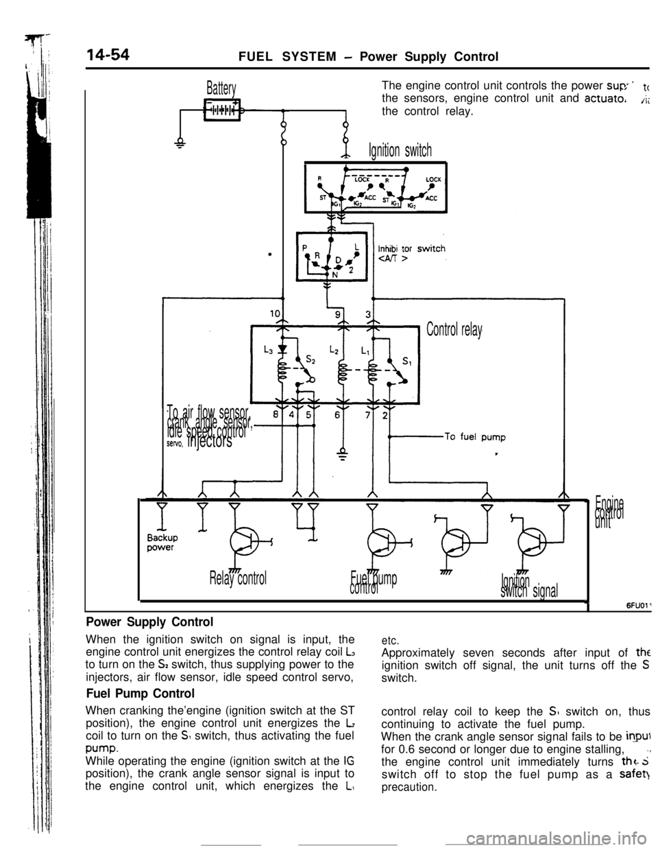
L11The engine control unit controls the power
suv ’tcthe sensors, engine control unit and
actuate,A;the control relay.
-P
.
-p.Ignition switch
Inn yr
To air flow sensor,crank angle sensor,idle speed controlsetvo. injectors
Control relay
Relay controlFuel pump
controlIgnitionswitch signal
Enginecontrol
unit
I6FUOl’
Power Supply ControlWhen the ignition switch on signal is input, the
engine control unit energizes the control relay coil
L3to turn on the
S2 switch, thus supplying power to the
injectors, air flow sensor, idle speed control servo,
Fuel Pump ControlWhen cranking the’engine (ignition switch at the ST
position), the engine control unit energizes the
Lcoil to turn on the
S switch, thus activating the fuel
pump.While operating the engine (ignition switch at the
IGposition), the crank angle sensor signal is input to
the engine control unit, which energizes the
L,
etc.Approximately seven seconds after input of
theignition switch off signal, the unit turns off the
Sswitch.
control relay coil to keep the
SI switch on, thus
continuing to activate the fuel pump.
When the crank angle sensor signal fails to be
inputfor 0.6 second or longer due to engine stalling,
.,the engine control unit immediately turns
thz. 5switch off to stop the fuel pump as a safet)
precaution.
Page 223 of 391
19-12POWER STEERING - Oil Pump
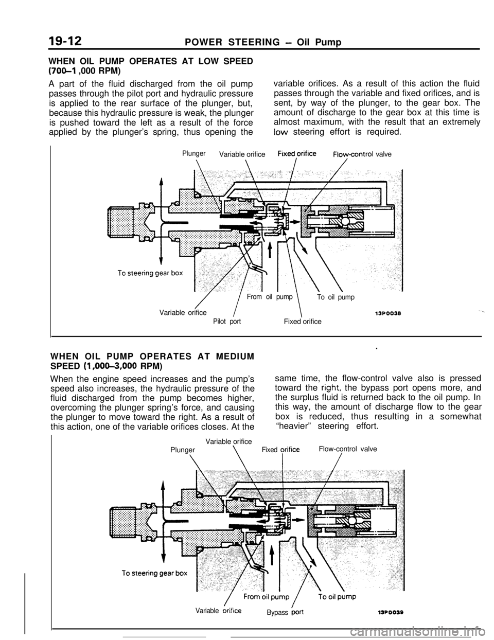
WHEN OIL PUMP OPERATES AT LOW SPEED
(70&l ,000 RPM)
A part of the fluid discharged from the oil pumpvariable orifices. As a result of this action the fluid
passes through the pilot port and hydraulic pressurepasses through the variable and fixed orifices, and is
is applied to the rear surface of the plunger, but,sent, by way of the plunger, to the gear box. The
because this hydraulic pressure is weak, the plungeramount of discharge to the gear box at this time is
is pushed toward the left as a result of the forcealmost maximum, with the result that an extremely
applied by the plunger’s spring, thus opening thelow steering effort is required.
PlungerVariable orificeFixed,orificeFioycontrol valve
/ I
From oil pump
To oil pumpVariable orifice
13POO38-.
Pilot portFixed orifice
.WHEN OIL PUMP OPERATES AT MEDIUM
SPEED
(1 ,OOm,OOO RPM)
When the engine speed increases and the pump’ssame time, the flow-control valve also is pressed
speed also increases, the hydraulic pressure of thetoward the
right, the bypass port opens more, and
fluid discharged from the pump becomes higher,the surplus fluid is returned back to the oil pump. In
overcoming the plunger spring’s force, and causingthis way, the amount of discharge flow to the gear
the plunger to move toward the right. As a result ofbox is reduced, thus resulting in a somewhat
this action, one of the variable orifices closes. At the“heavier” steering effort.
Variable orifice
PlungerFlow-control valve
\\Fixed yrifice/
Variable &iflceBypass ‘LrllJPOO59