engine oil MITSUBISHI ECLIPSE 1990 User Guide
[x] Cancel search | Manufacturer: MITSUBISHI, Model Year: 1990, Model line: ECLIPSE, Model: MITSUBISHI ECLIPSE 1990Pages: 391, PDF Size: 15.27 MB
Page 88 of 391
q7 --_-.-ENGINE
- General Information9-3TECHNICAL FEATURES
HIGH PERFORMANCE AND . . .._..............1. The DOHC 16-valve engine ensures excellent intake and exhaust
FUEL ECONOMYefficiency.
2. The rocker arm is of the roller-type-cam-follower design which Iminimizes friction loss.
3. The combustion chamber is of the pentroof type with a squish
area that offers outstanding combustion efficiency.
4. The multipoint fuel injection system is electronically
controlled.5. The intake manifold is the inertia supercharging type which
improves intake efficiency and the dual-type exhaust manifold
offers good exhaust efficiency.
6. The two-coil type electronic control ignition system ensures
good ignition performance.
LOW VIBRATION AND. . . . . . ..I.................1. The hydraulic lash adjuster, together with the roller rocker arm,
LOW NOISEcontributes to reduced operating noise of the valve mechanism.
2. A cogged type belt is used to drive the camshaft.
3. The auto tensioner maintains the optimum timing belt tension.
4. The torsional damper reduces twisting vibration in the crankshaft’
to a minimum.
5. The silent shaft system reduces engine vibration and rolling
’moment to a minimum
SERVICEABILITY . . . . . . . . . . . . . . . . . . . . . . . . . . . . . . . . . . . . .1. The self-diagnosis system makes troubleshooting easier.
2. The lash adjuster eliminates the need for valve clearance
adjustment.3. The auto tensioner eliminates the need for timing belt
tension adjustment.
-.--..-. --.-
Page 92 of 391
s’ y _._----,_ - k - ..-_ _ _
ENGINE- Base Engine9-7I
BASE ENGINE
Valve seat
Squish area
Spark plug hole
Exhaust portintake port
Piston O.D.
6EN0076Camshaft lubricatingValve guide
6ENO246Camshaft lubricating
oil passage
6ENO247
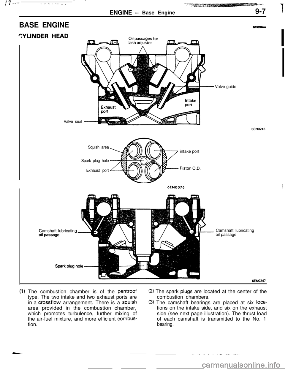
(1) The combustion chamber is of the pentroof(2) The spark plugs are located at the center of the
type. The two intake and two exhaust ports arecombustion chambers.
in a crossflow arrangement. There is a
squish(3) The camshaft bearings are placed at six loca-area provided in the combustion chamber,tions on the intake side, and six on the exhaust
which promotes turbulence, further mixing ofside (see next page illustration). The thrust load
the air-fuel mixture, and more efficient
combus-of each camshaft is transmitted to the No. 1
tion.
bearing.
- ._ _ _ - -,- -- .---
Page 94 of 391
CYLINDER BLOCKENGINE
- Base Engine9-9
Engine oil tocylinder
headCoolant inlet
ASilent
front
Engine oil main gallery
Silent shaft bearing,
rear
\shaft bearing,
A taw
Silenishaft bearing.
rearengine only)
6EN0246
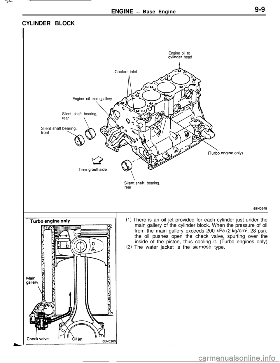
(1) There is an oil jet provided for each cylinder just under the
main gallery of the cylinder block. When the pressure of oil
from the main gallery exceeds 200
kPa (2 kg/cm’, 28 psi),
the oil pushes open the check valve, spurting over the
inside of the piston, thus cooling it. (Turbo engines only)
(2) The water jacket is the Siamese type.
Page 95 of 391
9-10PISTONENGINE- Base Engine
For non-turbo engineldentificatlonForturbo engine
Pin;nterline y FPiston ceyerline
6EN01246EN0125Steel strut6EN0249
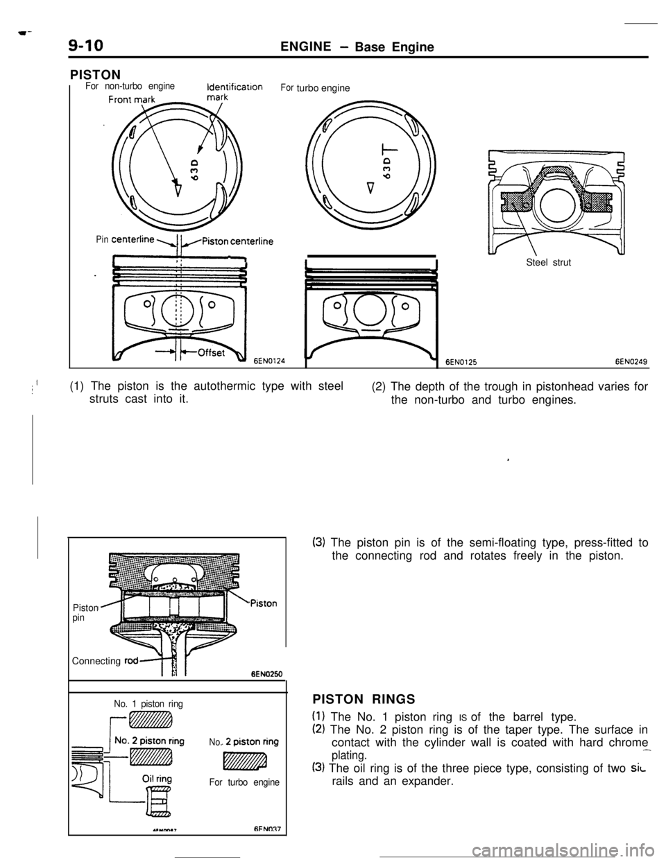
Ij(1) The piston is the autothermic type with steel
struts cast into it..(2) The depth of the trough in pistonhead varies for
the non-turbo and turbo engines.
Piston
pinConnecting
rod?\i
~Piston
6EN0250
No. 1 piston ringPISTON RINGS
No.3
For turbo engine
(1) The No. 1 piston ring IS of the barrel type.
(2) The No. 2 piston ring is of the taper type. The surface in
contact with the cylinder wall is coated with hard chrome
plating.-
(3) The oil ring is of the three piece type, consisting of two sLrails and an expander.
.,YM,,fiFNflR7
,
(3) The piston pin is of the semi-floating type, press-fitted to
the connecting rod and rotates freely in the piston.
Page 96 of 391
ENGINE- Base Engine9-11 7Oil jet
Front mark
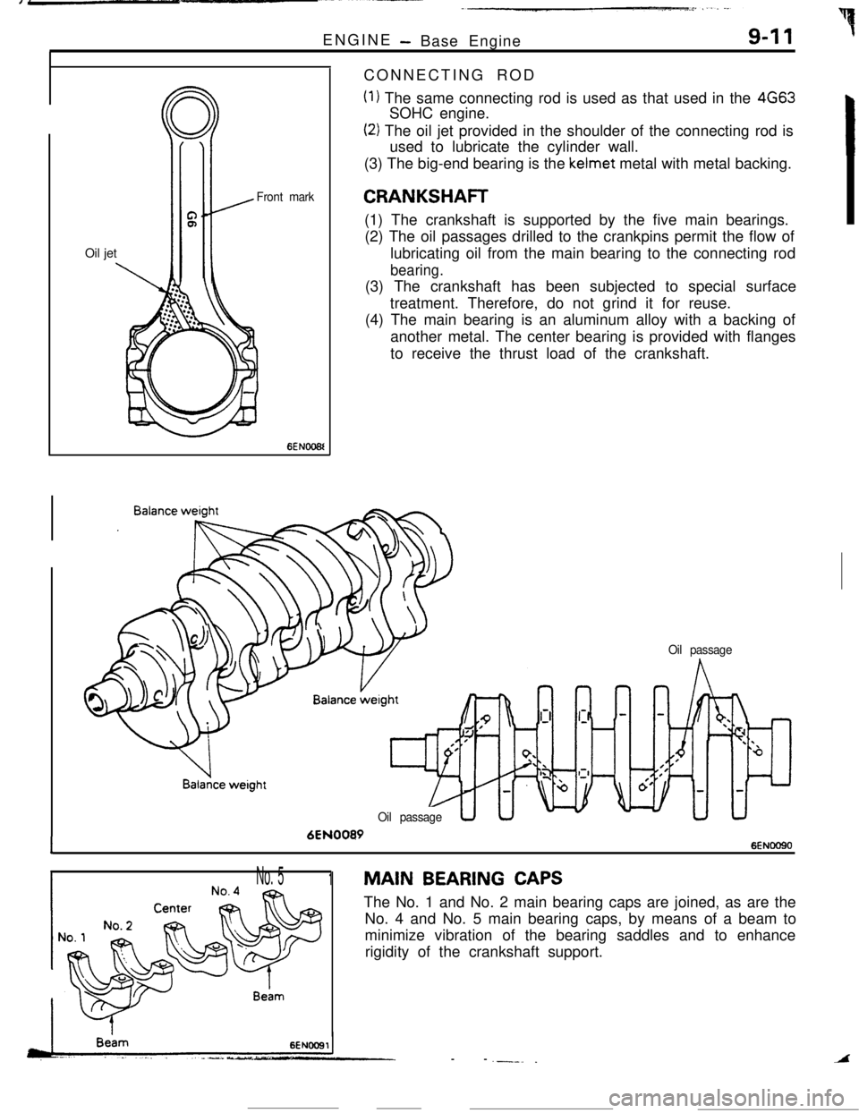
6ENOO6lCONNECTING ROD
(1) The same connecting rod is used as that used in the 4663SOHC engine.
(2) The oil jet provided in the shoulder of the connecting rod is
used to lubricate the cylinder wall.
(3) The big-end bearing is the kelmet metal with metal backing.
CRANKSHAFT(1) The crankshaft is supported by the five main bearings.
(2) The oil passages drilled to the crankpins permit the flow of
lubricating oil from the main bearing to the connecting rod
bearing.(3) The crankshaft has been subjected to special surface
treatment. Therefore, do not grind it for reuse.
(4) The main bearing is an aluminum alloy with a backing of
another metal. The center bearing is provided with flanges
to receive the thrust load of the crankshaft.
Oil passage
6EN0089
16ENOOQO
Oil passage
INo. 51MAIN BEARING CAPSThe No. 1 and No. 2 main bearing caps are joined, as are the
No. 4 and No. 5 main bearing caps, by means of a beam to
minimize vibration of the bearing saddles and to enhance
rigidity of the crankshaft support.
--
.--. _A
Page 99 of 391
ENGINE - Base Engine
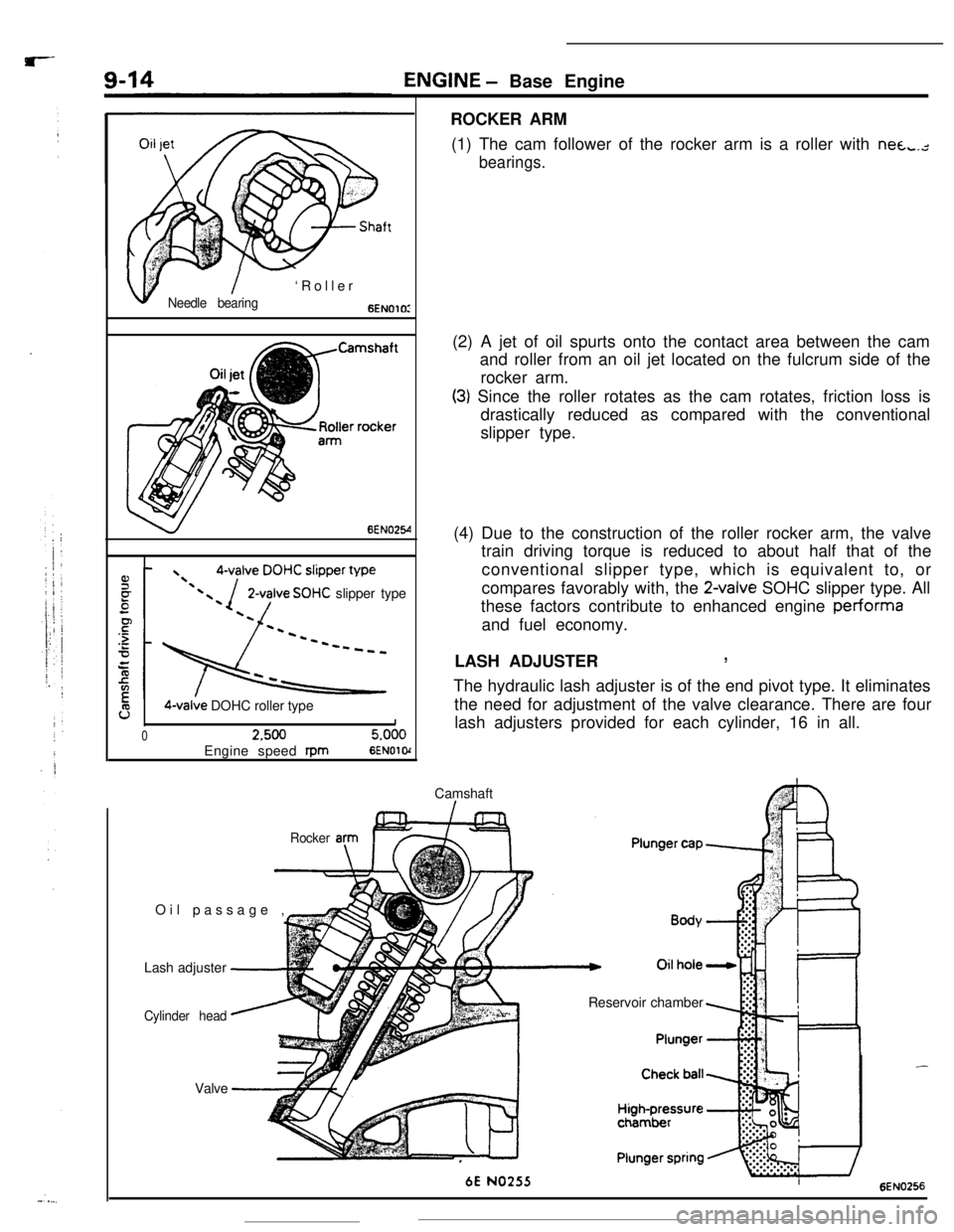
ROCKER ARM
(1) The cam follower of the rocker arm is a roller with nea,.,-
bearings.
v
,I$- I- ‘Roller
Needle bearing6ENOlOI
6EN025-4
2-valve SOHC slipper type
9O-valve DOHC roller type1
02.5005.000Engine speed
rpm6ENOl o(Camshaft
I-Oil passage ,
EIr(2) A jet of oil spurts onto the contact area between the cam
and roller from an oil jet located on the fulcrum side of the
rocker arm.
(3) Since the roller rotates as the cam rotates, friction loss is
drastically reduced as compared with the conventional
slipper type.
(4) Due to the construction of the roller rocker arm, the valve
train driving torque is reduced to about half that of the
conventional slipper type, which is equivalent to, or
compares favorably with, the
2-valve SOHC slipper type. All
these factors contribute to enhanced engine performa
and fuel economy.
LASH ADJUSTER
,The hydraulic lash adjuster is of the end pivot type. It eliminates
the need for adjustment of the valve clearance. There are four
lash adjusters provided for each cylinder, 16 in all.
Rocker anIF=Lash adjuster
-
Cylinder head
--Valve
‘-Reservoir chamber
6E NO255
-6EN0256
Page 100 of 391
5-jENGINE- Base Engine9-15Operation of the Lash Adjuster
When the valve starts opening
/f-b
During the valve opening stroke
n
6EN0254
When the valve coiqpletesthe opening stroke
6EN0257
6EN0256
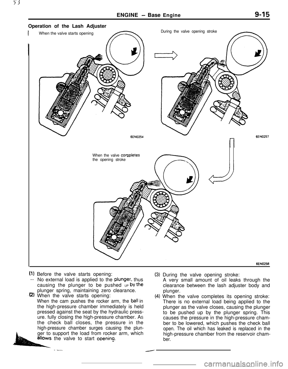
(1) Before the valve starts opening:
--
No external load is applied to the
plunger, thus
causing the plunger to be pushed UP
by theplunger spring, maintaining zero clearance.
.(2) When the valve starts opening:
When the cam pushes the rocker arm, the ball inthe high-pressure chamber immediately is held
pressed against the seat by the hydraulic press-
ure. fully closing the high-pressure chamber. AS
the check ball closes, the pressure in the
high-pressure chamber surges causing the plun-ger to support the load from rocker arm, which
.allows the valve to start ooenino.
- -__
(3) During the valve opening stroke:
A very small amount of oil leaks through the
clearance between the lash adjuster body and
plunger.
(4) When the valve completes its opening stroke:
There is no external load being applied to the
plunger as the valve closes, causing the plunger
to be pushed up by the plunger spring. This
causes the pressure in the high-pressure cham-
ber to be lowered, which pushes the check ball
open. The oil which has leaked is replaced in thehigh-pressure chamber from the reservoir cham-
ber.
-
Page 101 of 391
9-16ENGINE- Base Engine
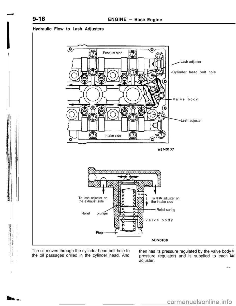
Hydraulic Flow to Lash Adjusters
To lash adjuster onthe exhaust side
P
)
5-Valve body
.Lash adjuster
6EN0107
:.-.
2:.
4
‘.’Relief plunger
I?.,:.:.;
/Lash adjuster
-Cylinder head bolt hole
PlugTo
tash adjuster onthe intake side
Relief spring
-Valve body
6EN0108The oil moves through the cylinder head bolt hoie to
the oil passages drilled in the cylinder head. Andthen has its pressure regulated by the valve body k
pressure regulator) and is supplied to each
la:
adjuster.
-:
Page 103 of 391
9-18ENGINE- Base Engine
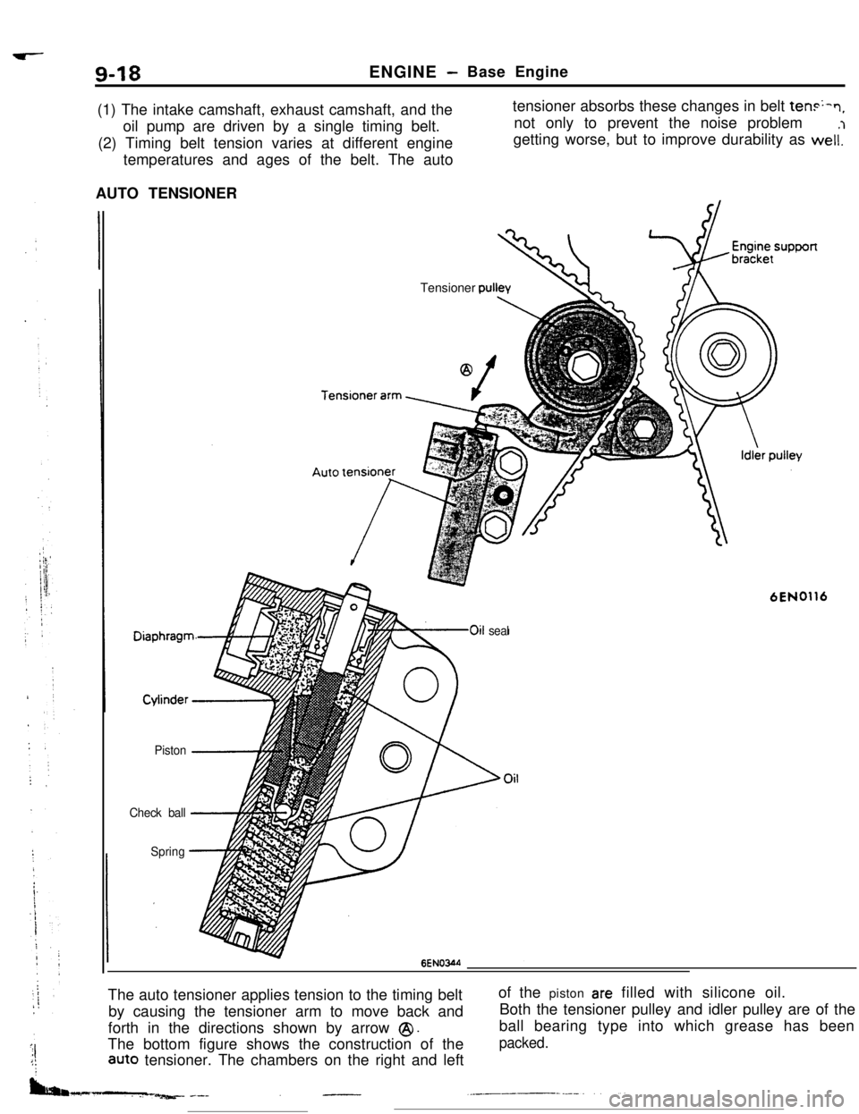
(1) The intake camshaft, exhaust camshaft, and the
oil pump are driven by a single timing belt.
(2) Timing belt tension varies at different engine
temperatures and ages of the belt. The autotensioner absorbs these changes in belt
ten+n,not only to prevent the noise problem
getting worse, but to improve durability as weli’l
AUTO TENSIONER
Piston -1
Check ball-4,
SpringTensioner
cwllev
6EN0116
LOoil seal
6ENOWThe auto tensioner applies tension to the timing belt
by causing the tensioner arm to move back and
forth in the directions shown by arrow
@I.The bottom figure shows the construction of the
aUt0 tensioner. The chambers on the right and leftof the piston
are filled with silicone oil.
Both the tensioner pulley and idler pulley are of the
ball bearing type into which grease has been
packed.
Page 104 of 391
,_-.._-~_._. I _ ‘... ----
ENGINE- Base Engine9-19
Reservoir
chamber/
Reservoir
chamber
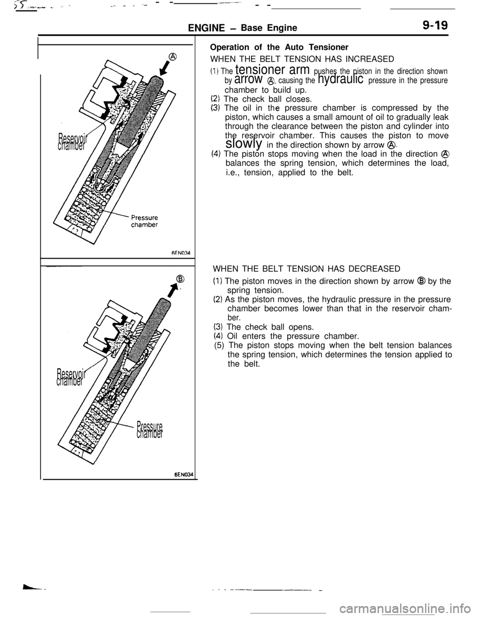
PressurechamberOperation of the Auto Tensioner
WHEN THE BELT TENSION HAS INCREASED
(1) The tensioner arm pushes the piston in the direction shown
by
arrow @, causing the hydraulic pressure in the pressurechamber to build up.
(2) The check ball closes.
(3) The oil inthepressure chamber is compressed by the
piston, which causes a small amount of oil to gradually leak
through the clearance between the piston and cylinder into
the reservoir chamber. This causes the piston to move
slowly in the direction shown by arrow
@.
(4) The piston stops moving when the load in the direction @balances the spring tension, which determines the load,
i.e., tension, applied to the belt.
WHEN THE BELT TENSION HAS DECREASED
(1) The piston moves in the direction shown by arrow @I by the
spring tension.
(2) As the piston moves, the hydraulic pressure in the pressure
chamber becomes lower than that in the reservoir cham-
ber.
(3) The check ball opens.
(41 Oil enters the pressure chamber.
(5) The piston stops moving when the belt tension balances
the spring tension, which determines the tension applied to
the belt.
_ . _ ---___- -